Abstract
Cast iron is a longtime reliable material for the production of heat-treated stressed castings, i.e., those that are long, are cyclically heated, and heat-stressed. The durability of thermally stressed castings used in practice is dependent on the choice of the optimum chemical composition, metallurgy of production, macro- and microstructures, construction, and the way of exploitation. Today, the successful solution of this problem is dominated by simulation programs. The comprehensive analysis of heat stress is very important, i.e., the impacts of various physical quantities on its rise, progress, and size. This paper provides a comprehensive analysis of thermal stress mechanisms in gray iron castings, with a particular emphasis on the relationships between the material properties, microstructural characteristics, and component performance under thermal loading conditions. The theoretical foundations are complemented by experimental data, establishing practical guidelines for optimizing cast iron compositions and processing parameters for thermal applications.
1. Introduction
Cast iron is the oldest manufactured material based on iron, and it retains leadership among other casting materials, while leadership is falling on castings made from cast iron. It is also a longtime reliable material for the production of heat-treated stressed castings, i.e., those that are long, cyclically heated, and heat-stressed.
The global share of cast iron castings for the year 2010 was 73% [1]. Cast iron remains one of the most widely used foundry materials globally, maintaining its dominant position despite advancements in alternative materials. Recent data from the 57th Census of World Casting Production indicates that cast iron still constitutes approximately 70% of the global casting production volume, with gray iron representing 45.4% of this total [2]. This sustained prominence can be attributed to cast iron’s excellent combination of mechanical properties, thermal characteristics, and economic efficiency.
Gray cast iron is particularly well-suited for thermally stressed applications—components subjected to prolonged or cyclical thermal loading. These applications span diverse industrial sectors, including metallurgical equipment (molds, furnace fixtures, and smelters), automotive components (engine blocks, cylinder heads, and exhaust manifolds), and industrial machinery [3]. Recent investigations into thermal stress mechanisms by Liu et al. [4] and Mohammadi et al. [5] have established comprehensive frameworks for understanding thermal fatigue failure mechanisms in cast iron components.
The performance and service life of thermally stressed castings depend critically on multiple interrelated factors: the chemical composition, microstructural characteristics, manufacturing methodology, and operational conditions. Optimizing these parameters requires detailed knowledge of thermal stress mechanisms and accurate predictions of component behaviors under various thermal conditions. Modern computational approaches, including advanced finite element analysis and microstructure-based simulation methods, have significantly enhanced our ability to predict thermal stress development [6,7].
Guo et al. [8] demonstrated that thermal gradient control through microstructural engineering can significantly improve the thermal fatigue resistance of gray iron castings.
The global iron casting market size was valued at USD 101.17 billion in 2021 and is expected to expand at a compound annual growth rate (CAGR) of 6.1% from 2022 to 2030. Factors including favorable government policies toward the manufacturing sector and investment in rail infrastructure are anticipated to propel market growth [9].
Since 1966, under the influence of the world economic development cycle, political climate, and unexpected events, the world casting output has increased and decreased, but exhibits an overall upward trend. The total output increased from 63,261,475 tons in 1966 to 103,223,514 tons in 2013, to an all-time high of 112,738,168 tons in 2018, an increase of 78 percent. In 2019, the output dropped slightly, and affected by the worldwide novel coronavirus epidemic in 2020, the output dropped to 105,505,602 t [10].
Cast iron is the most suitable material for producing thermal-stressed castings, i.e., those castings that are heated for a long time or are cyclically thermally stressed. Research on thermal stresses was performed by [11,12]. It is concerned with metallurgical castings (molds, parts of furnace fixtures, smelters, furnace bars, pipes, etc.) but also the castings for the automotive industry and households. It is also the economically cheapest material for the production of such castings (parts and components). The lifetime of thermally stressed castings used in a common practice is mainly dependent on the choice of the optimal chemical composition and metallurgical production, structure, and methods and conditions of exploitation. It is necessary to know the purport of thermal-stressed cast iron and thermal stress conditions in detail (levels working temperatures or their fluctuations, i.e., thermal duty cycle) for the right choice of the chemical composition and structure (macro and micro) of the material. The successful solution of this topic is now provided by means of a computer (simulation programs), including the design optimization of components (castings). This requires a comprehensive theoretical analysis of the purport of thermal stress, i.e., the influence of physical parameters on its origin, course, and size. The process of simulation of temperatures and stresses was researched by [13]. Research on the formation of microstructure and residual stresses in castings was performed by [14,15].
Cast irons are a family of ferrous alloys with a carbon content ranging from 2.5 to 5%. They have a wide range of applications in automotive, industrial, agriculture, and construction industries. The primary classification of cast irons is based on the graphite morphology, which can be in the flake, vermicular, or spheroidal forms. The mechanical properties of cast irons depend on the matrix microstructure and graphite morphology; different alloying elements can be added to improve their high-temperature mechanical performance. Creep is an important deformation mechanism for high-temperature applications of cast irons. Research on the creep behavior of cast irons, especially for compacted graphite iron (CGI), is limited. Original results from tensile and compression creep tests on CGI emphasize a significant difference in creep behavior under tensile and compressive loading [16].
The solidification of materials depends on the cooling rate of the materials, which is governed by heat flow in the mold and alloy composition. The solidification rate also affects the structure and properties of the materials. Shaha and Haque [17] analyzed the heat flow of a cold-set resin-bonded sand mold, simulated by JL Analyzer FEM analysis software. To verify the model, the gray cast iron was melted at 1350 °C and poured into a mold at 1300 °C. Most of the heat reserve was at the junction of the mold, which was nearer to the source of liquid metal, and the lowest heat reserve was at the end of the mold. So, the solidification rate was very high at the end of the mold wall, whereas it was comparatively low near the sprue of the mold. Depending on the heat flow through the mold, the solidification rate changed the microstructure from chilled to mottled and gray cast iron, and the hardness changed from 95.1 HRB to 78.78 HRB.
The essences of thermal stress are
- Thermal tension (cracking and crushing);
- Oxidation of the surface (scaling losses and singeing);
- Growth (a permanent increase in volume).
This paper provides a comprehensive analysis of thermal stress mechanisms in gray iron castings, with a particular emphasis on the relationships between material properties, microstructural characteristics, and component performance under thermal loading conditions. The theoretical foundations are complemented by experimental data, establishing practical guidelines for optimizing cast iron compositions and processing parameters for thermal applications.
Recent advances in high-temperature in situ characterization techniques have enabled the real-time observation of microstructural evolution during thermal cycling, as demonstrated by Chen et al. [18]. These insights, combined with advanced computational models, have facilitated the development of predictive lifetime assessment methodologies, allowing for a more accurate estimation of the component service life under complex thermal conditions [19,20].
2. Thermal Tension
It is the most serious stress. Its size is determined by Hoocke’s law:
where
σ—resulting strain [MPa];
E—modulus of elasticity [MPa];
α—coefficient of linear expansion (expansion) [K−1];
Δt—temperature difference (gradient) [°C].
Some views on the subject of self- or residual stresses and clarity on some formulations that are widely used in castings and their classification (thermal, shrinkage, and phase stresses) are presented by Maj [21]. For example, the location of their occurrence is often not specified, nor in which cross-sections (volumes) they are occurring. In thin bars, there are uniaxial stresses, and in thin plates, stresses in two orthogonal directions are considered, while in castings, which are always three-dimensional objects, stresses in all planes should be considered. The author also presents selected methods of stress and strain testing, with a particular emphasis on elasto-optical testing.
The importance and value of individual coefficients are described below.
- (a)
- The modulus of elasticity E is a characteristic attribute of each material. The reference values for cast iron are as follows:
GJL/gray cast iron/E = 6 ÷ 14.104 MPa (normally 10.104);
GJS/ductile iron/E = 16 ÷ 18.104 MPa (normally 15.104);
Steel for castings E = 21.104 MPa.
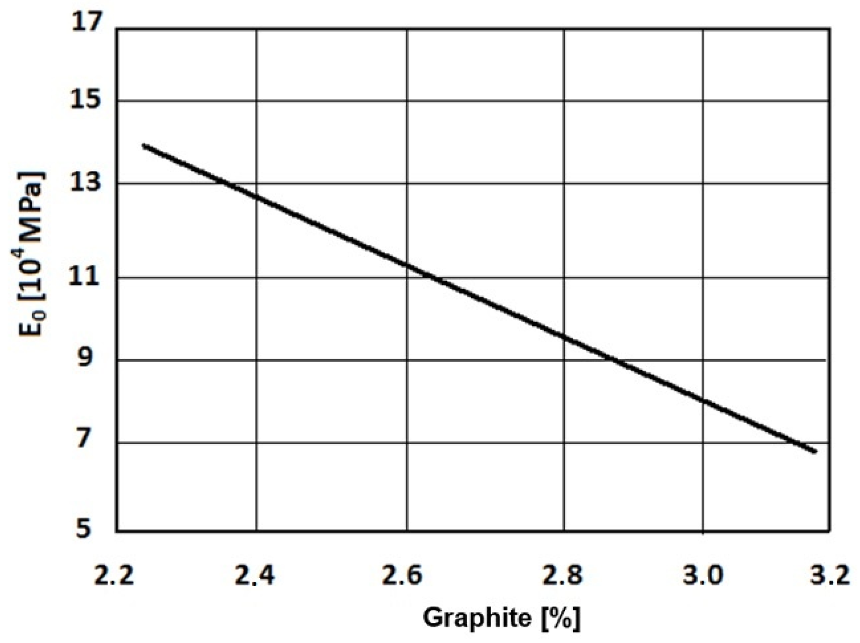
Its value depends mainly on the proportion of graphite in the structure of GJL, as shown in Figure 1 [22], and it rapidly increases with a decrease in the content of graphite. Therefore, it is necessary to ensure the highest graphitization ability in cast iron. This means the highest Sc (degree of saturation) and slow solidification of the casting speed.
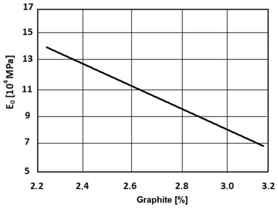
Figure 1.
E0 dependence on the content of graphite.
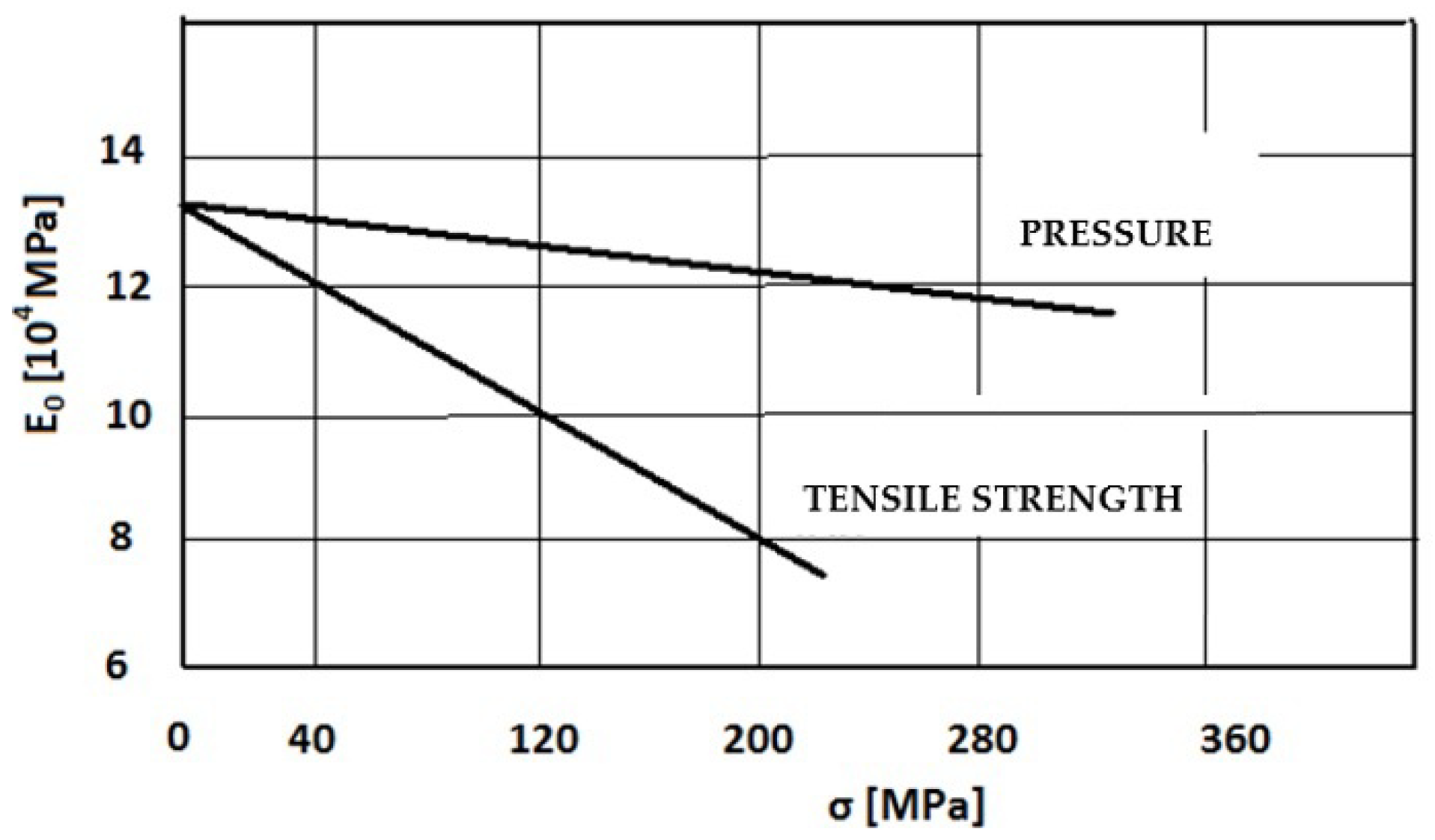
In terms of material breach (break and failure), tensile stress is dangerous; that is why the modulus of elasticity in tensile strength is more significant than in pressure. Both values decrease in GJS with an increase in tension [22], as shown in Figure 2.
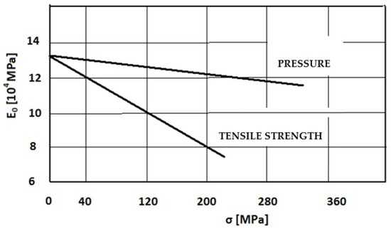
Figure 2.
E0 dependence on the load σ.
The modulus of elasticity of all cast irons decreases with increasing temperature, which is preferred because the mechanical properties decrease with temperature. The plasticity is also increased (plastic deformations occur).
- (b)
- The coefficient of linear expansion α is a physical parameter that depends on the type of metal and composition of a casting. It specifies the expansion of materials caused by a temperature change (or shrinkage during cooling). Its value is determined by the following formula:
The value α changes (usually increases) with temperature, and so it is determined for each temperature range in practice. The values of α for the most used casting materials and its changes at higher temperatures are shown in Table 1 [22,23].

Table 1.
The value of α and its increase with temperature.
The values of α in GJL depend on its microstructure and on the interrelations of the structural components. Their certain values between temperatures of 20 and 200 °C [106.K−1] are ferrite, 12.5; austenite, 18.5; cementite, 6.5; pearlite, 11.5; and graphite, 7.5 to 25. This overview indicates that the lowest α is achieved with the GJL material, which has the highest ratio of graphite, a requirement necessary for practical use [23].
- (c)
- The temperature gradient Δt is very significant in connection with the thermal stress, and even its maximum value (size) as well as its time pattern. The maximum value Δt is determined by operating conditions—the required heating temperature. It cannot be controlled (reduced) in most cases in practice. However, the heating rate is important, which should be as low as possible. Thermal shocks, i.e., rapid heating and cooling of castings, are very undesirable. The change and the maximum value of the temperature gradient, especially in cyclical heating, mainly depend on
- The thermal conductivity of the material;
- Thermal capacity of the material,
- Casting construction (wall thickness).
- (d)
- Thermal conductivity λ [W.m−1.K−1] significantly affects the formation of temperature gradients and their size, and thus the resulting tension inversely. It is very diverse in different metals. It also decreases in the casting materials (micro-shrinkages, pores, bubbles, etc.). It is also different for the structural components of cast irons, as shown in Table 2. Temperature conductivity decreases with increasing temperature (melting up to 30% of the original value). It decreases at about 8 ÷ 10% at a temperature of 500 °C. The dependence of specific thermal conductivity on temperature is given by
Table 2. Thermal conductivity of some metals, cast irons, and their structural components.
—the temperature dependence coefficient of the thermal conductivity of a material.
The relatively high thermal conductivity of GJL is mainly related to the high conductivity of graphite, which is very variable in terms of its quantity, shape, size, and particularly the orientation (direction of an order). The graphite flakes oriented in the direction of heat transfer provide many times higher conductivity. A high density of thin graphite plates with their partial connections (touches) are also preferred.
- (e)
- The specific thermal capacity c [kJ.kg−1.K−1] (specific heat) is an important physical value associated with the formation and course of thermal processes. The values of individual metals and their alloys are very different, as shown in Table 3 [22]. A higher value is preferable with regard to the thermal stress of castings, because at the same heat input, it reduces the thermal rate and temperature gradients and, finally, the tension in the walls of castings.
Table 3. The specific thermal capacity of some metals and structural components.
Increasing the specific heat of LLG is mainly achieved by increasing the rate of graphite in the structure, but the pearlite structure is more suitable for the basic metal mass.
- (f)
- The ductility of the material A [%], which determines plastic characteristics of the material, is very low (0.2 ÷ 0.8%) in GJL, but it is slightly increased with temperature. This reduces the resulting tension due to the causes of plastic deformation, especially at temperatures exceeding ΔtK, e.g., the area of flexible–plastic deformation (for GJL the critical temperature (range) ΔtK = 380 ÷ 410 °C) [23].
- (g)
- The construction of castings in the context of thermal stress and hence lifetime under operating conditions is an important factor, as well as the physical properties of the material and exploitation conditions (stress mode). The most important factor is the determination (calculation) of the optimum wall thickness in each section (cross-section) of the casting, depending on the size and time course of thermal stress. While increasing the wall thickness of castings (elements) increases the mechanical strength, it also increases the temperature gradient Δt, i.e., the temperature difference between the heated and cold (outside) wall. Today, in practice, there are various ways of calculating the optimum wall thickness for certain castings for determined procedures of thermal stress. Particular cases are the cast iron molds for steel casting or casting under pressure. The following formula, for example, calculates the optimal wall thickness hs of heavy steel molds [1]:
Ds is the mean diameter (cross-section) of the ingot;
Ds = [m];
a, b are the cross-sectional dimensions of the ingot [m].
It is necessary to specify (to optimize) hs for the specific conditions of exploitation in practice. The wall thickness is also linked to the weight of the ingot, which should be as low as possible due to material consumption. It is necessary to ensure a high exploitative last (life), and mainly the lowest specific consumption expressed in kg of cast iron per 1 ton of cast iron–steel by other design modifications (reducing the wall thickness in the corners for their height, ribbing, bandaging, etc.)
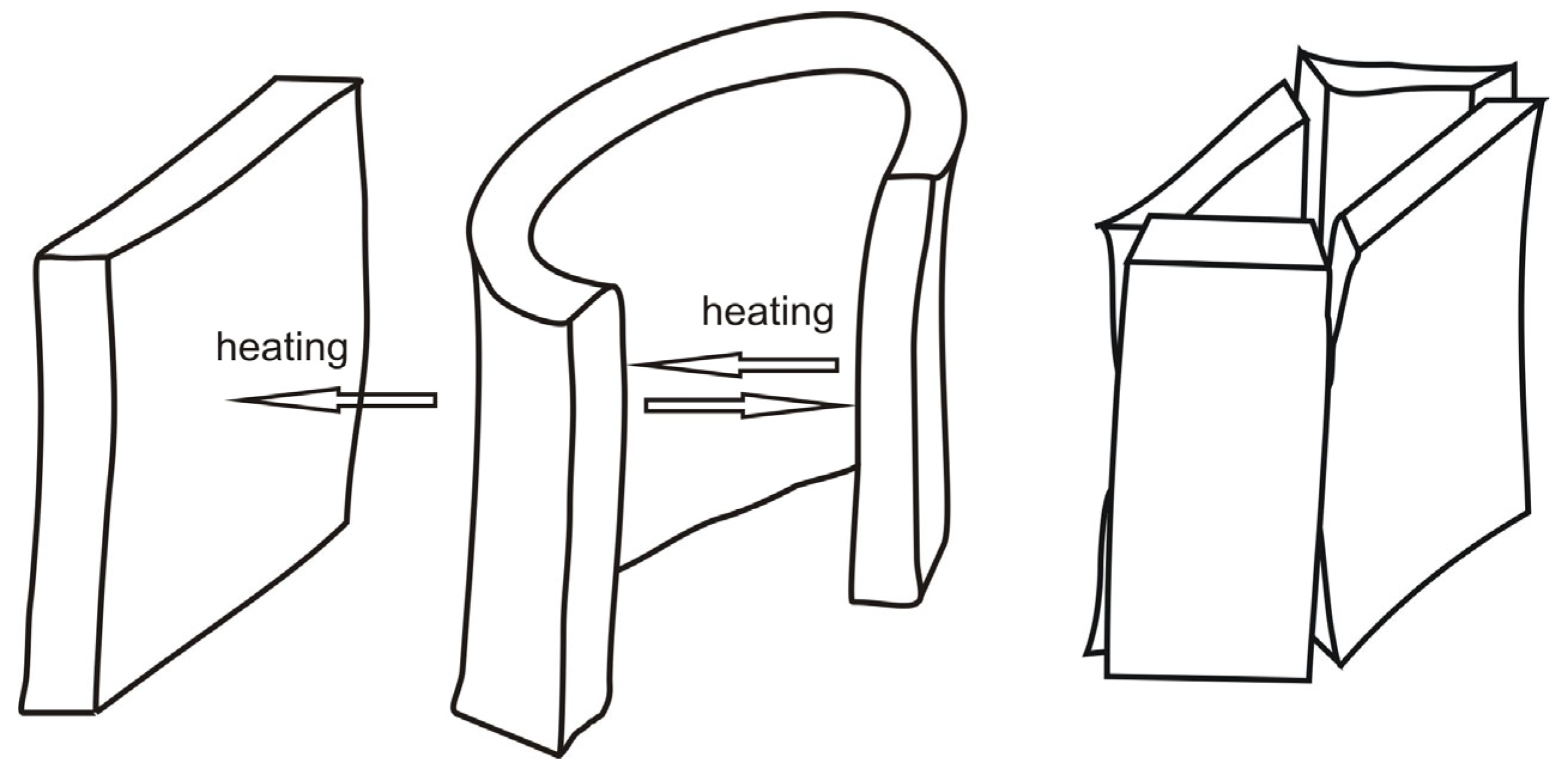
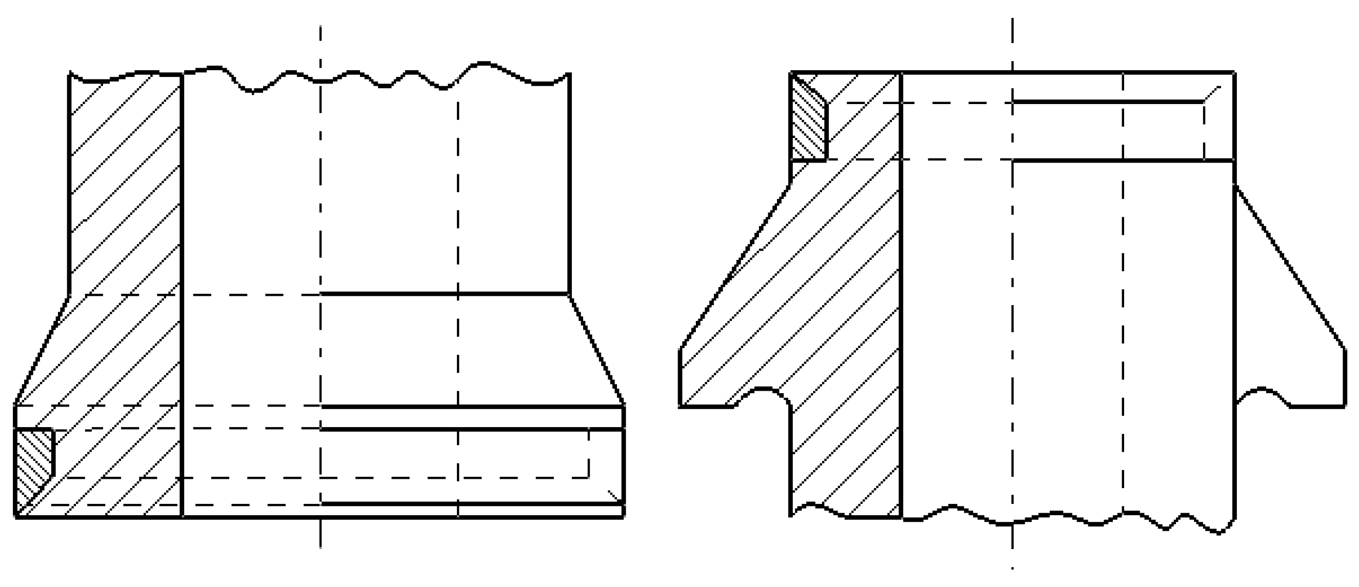
An example of thermal stress of a metal plate and the walls of ingots is shown in Figure 3. The structural modification (strengthening of ingots’ ends) to reduce longitudinal cracking is shown in Figure 4 [11].
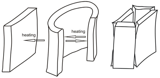
Figure 3.
Heating and deformation of a metal plate and ingots.
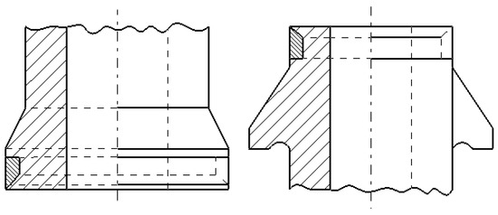
Figure 4.
Hardening of the ends of the ingot by the flange and the steel tire.
3. Numerical Procedures to Determine Thermal Stresses
To ensure a long life, and especially to reduce the consumption of thermally stressed castings (parts), it is important to ensure their optimal structure, by which it is ensured a minimum formation of temperature differences and hence stresses. This is a rather complex problem for designers, which is now successfully solved by numerical simulation [24]. This modelling is provided in 2D and 3D, where products (castings) are often generated in complicated and difficult shapes to minimize thermal stresses that lead to damage and decapitation. Now a number of CAD systems (Computer-Aided Design) and FEA (Finite Element Analysis) and various universal systems are used for the purposes of simulation and modelling. The bases are highly sophisticated models of the approximation of physical quantities; usually, they enable the optimization of the design by a fairly complicated way that is possible when entering geometric, material, and limit data. The result is a graph of the temperature, stress, and deformation (strains) of a casting and other required parameters. Their correct identification by an accurate database is crucial, i.e., very specifically determined physical parameters, which are significantly changed with the chemical composition and the macro and microstructure of the material used. Inaccurate inputs lead to indirect results [25,26]. A graphic interpretation of temperatures in a particular casting (crane wheel) is shown in Figure 5. The simulation was created using NovaFlow&Solid CV 4.6r4 software [27].
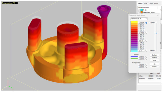
Figure 5.
Temperature behavior in a casting.
4. Surface Oxidation (Scaling)
The creation of scales on the surface of thermally stressed castings consists of oxidation, which gradually penetrates deeply, especially in GJL with graphite. At temperatures up to 700 °C, there is a predominance of oxidation of the base metal mass, and above this temperature, starts the oxidation of graphite, which burns out and allows access to oxygen deep below the surface (up to several mm). Therefore, the speed and depth of oxidation increase with the size and amount or orientation of graphite. An inappropriate material is rough graphite oriented perpendicularly to the surface. A “casting crust” is important, which should be compact and the thickest (up to 5 mm). Its quality can be influenced by special coatings in a molding form. Abrasion or mechanical treatment of the casting’s work surface (exposed graphite) is ineligible.
The adherence and compactness of scales are also important. It is higher in the cast irons than steels, and it can be improved by low alloying with chrome (0.3 ÷ 1.0%) and nickel (0.1 ÷ 0.3%), mostly in a combination [23].
High silicon and molybdenum (SiMo) ductile iron is commonly used for car exhaust systems. Its micro-structural dispersity depends on the intrinsic parameters, which include the alloy composition and inoculation efficiency, as well as extrinsic factors, such as the casting wall thickness and molding material, which define the cooling rate during solidification. Micro-structural dispersity is referred to as the degree of heterogeneity of the sizes of structural constituencies within the microstructure.
A variation in the micro-structural dispersity could impact the high-temperature performance of SiMo ductile iron during static oxidation and transient thermo-mechanical loading conditions. In the study by Lekakh, Bofah, and Godlewski [28], static high-temperature tests were performed on SiMo ductile iron solidified in a casting with varying wall thicknesses from 5 mm to 100 mm. The faster solidified specimens (taken from near chilled casting surfaces) had an extremely high micro-structural dispersity as compared to the thicker section samples. After thermal exposure, each of the samples was characterized using 2D sections and 3D μCT images, and the results indicated an order of magnitude difference in the graphite phase dispersity. The surface degradation was quantified after static oxidation experiments were implemented at temperature intervals between 650 °C and 800 °C. A non-destructive μCT 3D analysis and SEM/EDS were performed on cross-sections and used to quantify the scale topology and structure. A carbon analysis was used to decouple the scale formation and decarburization phenomena that occurred within the samples. These methods enabled the quantification of the oxidation of the SiMo cast iron with different micro-structural dispersity levels after being exposed to high-temperature static oxidation.
5. Cast Iron Growth
It means a permanent increase in the casting size, while its long exploitation at increased temperatures (over 500 °C) can reach values up to 0.7% of the original size.
The cause of the growth is the decay of pearlite to ferrite and graphite, which is accompanied by volume expansion. Deep internal oxidation of the base material, especially ferrite, can even increase the growth.
Consequent to the growth is a change in casting shape (bowing) in the most thermally exposed places, and it leads to permanent damage, especially in the fixed assembly of castings (components) in a structure. The growth of cast iron is most associated with the carbon content and temperature, as well as with the exploitation atmosphere. Superheated steam and gases are harmful.
Reducing the growth is reached by low alloying with pearlite (its cementite) stabilizers, which slows down graphitization and increases the resistance to scaling. These alloys are Cr, Mn, and Mo (0.1 ÷ 0.3%). Then, there are the alloys that increase the proportion of ferrite (Si and Al) or austenite (Ni, Mn, and Cu) and reduce the proportion of unstable pearlite [22,23].
6. Cast Iron Composition
Cast irons designated for the production of thermally stressed castings, i.e., to the max. of 800 °C, can be divided into two groups.
- (a)
- Unalloyed cast iron (hematite, fire-resistant) is characterized by a high content of C (over 3.8%), a reduced content of Si (1.2 ÷ 1.8%), and low contents of harmful accompanying elements (S, P, Pb, As, and Sb). Their production from pure raw iron (hematite) is made to replace the iron used for the production of GJS. Synthetic cast iron is less suitable, even if it is sufficiently “clean”, due to the high content of N (above 60 ppm), which increases the proportion of pearlite. A higher Mn content is desirable (0.7 ÷ 1.2%)—thermally stabilized pearlite [29].
An example of the composition is C from 3.8 to 4.2%; Si 1.2 ÷ 1.8%; Mn 0.7 ÷ 1.2%; P max 0.1%; Smax. 0.03%, and trace amounts of Pb, Sb, As, and Sn (0.001 ÷ 0.01%) [23].
- (b)
- The most appropriate alloying elements are Cr (0.3 ÷ 2%), Ni (0.1 ÷ 1.7%), and Mo (up to 0.3%), which significantly increase the thermal strength. They are suitable for about 850 °C, and they show many times lower scaling (scaling loss), growth, and a high strength at increased temperatures (thanks to Mo).
An example of the composition is C 3.2 ÷ 3.6%; Si 2.0 to 2.2%; Mn 0.6 ÷ 0.8%; P up to 0.1%; S up to 0.05%; Cr 0.3 ÷ 0.5%; Ni 0.1 ÷ 0.5%, and Mo 0.1 ÷ 0.3% [23].
It is used a very wide range of cast irons in practice, each for a very specific purpose, depending on the process of the thermal stress. Moderately and highly alloyed cast irons are in a group of refractory cast irons.
7. Discussion
The determination of the thermal stress fundamentals of device components (usually castings) is complex and a still a relatively unexplored problem. The most serious factors influencing the dependability and lifetime of thermo-stressed parts are mechanical thermal stresses, oxidation (singeing), and the growth of cast iron. The result is the cracking of components, most often, or the deformation of a structure and its malfunction.
It is possible to eliminate internal stress in castings from cast iron by metallurgical ways (microalloying, e.g., Ti) and thus prevent defects that cause stress [29].
The integration of computational modeling with experimental validation has become an essential approach in contemporary thermal stress research. Recent work by Wang et al. [30] employed multi-scale modeling techniques to simulate the microstructural evolution during thermal cycling, while Kiani et al. [31] developed physics-based models accounting for thermomechanical interactions at the microstructural level.
Industrial applications of these advancements have yielded notable improvements in component performance. Hashim et al. [32] reported a 35% increase in thermal fatigue resistance for brake discs through targeted micro-structural modifications, while Xiangbin et al. [33] demonstrated an extended service life of high-temperature pipeline components through optimized casting parameters.
Cast iron castings are the most often used for thermally stressed components because of their suitable physical properties (high thermal conductivity, low dilatation with temperature changes, low modulus of elasticity, higher specific heat, and slower surface scaling of castings). Some disadvantages of GJL are its very high fragility and a specific phenomenon—volume growth over time. There is a very wide range of cast irons, often designed for a very specific purpose (the way of thermal stress), providing reliable service and long-life devices.
8. Conclusions
This paper provides an analysis of thermal stress mechanisms in gray iron castings, their sources, as well as possibilities for their reduction or elimination. It takes into account the composition of the cast iron, its structure, physical properties, and the method of thermal stress. It is based on an analysis of literary sources that deal with the relevant issue. This paper addresses critical issues related to the longevity of thermal-stressed castings commonly utilized in various applications. It is essential to understand the intricate nature of thermal stress in cast iron, as well as the conditions that contribute to it, such as the operational temperature levels and their fluctuations, referred to as the thermal duty cycle. This understanding is crucial for making informed decisions regarding the appropriate chemical composition and structural characteristics (both macro and micro) of the material, including using simulations.
Author Contributions
Conceptualization, P.F. and J.P.; methodology, P.B.; software, M.B.; validation, M.S., M.B. and P.F.; formal analysis, P.F.; investigation, A.P.; resources, P.F.; data curation, J.P.; writing—original draft preparation, P.F.; writing—review and editing, P.F. and A.P.; visualization, P.B.; supervision, M.S. and M.B.; project administration, P.F. and A.P.; funding acquisition, P.F. All authors have read and agreed to the published version of the manuscript.
Funding
This work was supported by the Scientific Grant Agency of The Ministry of Education of the Slovak Republic Nos. VEGA 1/0001/25, VEGA 1/0359/25, APVV-22-0580, and KEGA 024TUKE-4/2025.
Data Availability Statement
No new data were created or analyzed in this study.
Conflicts of Interest
The authors declare no conflicts of interest.
References
- Lickfett, H. Gussproduktion 2010-globale Trends. Giesserei 99 2012, 2012, 154–157. [Google Scholar]
- Miskiewicz, R.; Volniak, R. Practical application of the industry 4.0 concept in a steel company. Sustainability 2020, 12, 5776. [Google Scholar] [CrossRef]
- Leitner, M.; Garb, C.; Riedler, M.; Grün, F. Microstructural assessment of thermal damage in cast iron brake discs. Eng. Fail. Anal. 2020, 110, 104412. [Google Scholar] [CrossRef]
- Liu, D.; Liu, Y.; Wu, Z.; Yang, Y. Thermal fatigue behaviors of compacted graphite iron and flake graphite iron. Materials 2022, 15, 1387. [Google Scholar] [CrossRef]
- Mohammadi, A.; Alizadeh, M.; Kazemi, S. Investigation of thermal fatigue behavior in centrifugally cast Ni-resist austenitic cast iron. Mater. Sci. Eng. A 2020, 788, 139500. [Google Scholar] [CrossRef]
- Elmquist, L.; Diószegi, A.; Björklind, T.O. On the formation of primary austenite and eutectic cells in grey iron and its effect on the thermal gradients during solidification. IOP Conf. Ser. Mater. Sci. Eng. 2019, 529, 012020. [Google Scholar] [CrossRef]
- Rashid, A.K.; Khalaf, A.; Al-Sahib, N.; Hanna, A. Modeling and simulation of brake disk-pad system using advanced finite element analysis. Eng. Technol. J. 2021, 39, 1821–1833. [Google Scholar]
- Guo, Y.; Li, Y.; Wang, X.; Guo, Z. Thermal shock behavior of gray cast iron under alternate cooling-heating loads. Materials 2020, 13, 856. [Google Scholar] [CrossRef]
- Grandviewresearch. Available online: https://www.grandviewresearch.com/industry-analysis/iron-casting-market-report (accessed on 28 April 2025).
- The Leading Metals Information Provider. Available online: https://news.metal.com/newscontent/101787233/the-challenge-of-cast-iron-today-and-its-future-development-trend (accessed on 28 April 2025).
- Anwar, M.Y. A study on thermal cracking of cast iron. In Proceedings of the Pakistan Engineering Congress, 70th Annual Session Proceedings, Punjab, Pakistan, 23 October 2006; pp. 414–422. Available online: http://pecongress.org.pk/images/upload/books/Paper677.pdf (accessed on 25 May 2025).
- Moonesan, M.; Honarbakhsh raouf, A.; Madah, F.; Habibollah, Z.A. Effect of alloying elements on thermal shock resistance of gray cast iron. J. Alloys Compd. 2012, 503, 226–231. [Google Scholar] [CrossRef]
- Manesh, A.A.I.; Segerlind, L.J. Simulation of heat transfer and stress analysis of continuous casting. Arch. Appl. Mech. 1991, 61, 393–403. [Google Scholar] [CrossRef]
- Maijer, D.; Cockcroft, S.; Jacot, A. Modeling of microstructure and residual stress in cast iron calender rolls. Metall. Mater. Trans. A 2000, 31, 1201–1211. [Google Scholar] [CrossRef]
- Bumbálek, L. Zbytková napětí určovaná pomocí Barkhausenova šumu. Strojírenská technologie 2004, IX, 11–15. [Google Scholar]
- Joshi, A.; Baxevanakis, K.P.; Silberschmidt, V.V. High-Temperature Creep of Cast Irons. In Solid Mechanics, Theory of Elasticity and Creep; Altenbach, H., Mkhitaryan, S.M., Hakobyan, V., Sahakyan, A.V., Eds.; Springer: Cham, Switzerland, 2023; Volume 185. [Google Scholar] [CrossRef]
- Shaha, S.K.; Haque, M.M. Simulation of Heat Flow in Computational Method and Its Verification on the Structure and Property of Gray Cast Iron. Am. J. Appl. Sci. 2010, 7, 795–799. [Google Scholar] [CrossRef]
- Chen, R.; Xu, Q.; Liu, B.; Zhang, J. In situ observation of graphite morphology changes during thermal cycling of gray cast iron. Mater. Charact. 2020, 167, 110494. [Google Scholar] [CrossRef]
- Ekström, M.; Jonsson, S. High-temperature mechanical and fatigue properties of cast alloys intended for use in exhaust manifolds. Mater. Sci. Eng. A 2014, 616, 78–87. [Google Scholar] [CrossRef]
- Venkatesan, K.; Subramanian, R. Analysis of mechanical and thermal properties of cast iron with boron carbide composites. Metall. Mater. Trans. A 2022, 53, 660–670. [Google Scholar]
- Maj, M. The Formation of the Strength of Castings including Stress and Strain Analysis. Materials 2024, 17, 2484. [Google Scholar] [CrossRef]
- Jelč, I. Výroba Hutníckych a Ťažkých Odliatkov; VŠT: Košice, Slovakia, 1983. [Google Scholar]
- Futas, P.; Pribulova, A.; Pokusova, M.; Junakova, A. Liatiny, Vlastnosti, Výroba, Použitie; TUKE: Košice, Slovakia, 2020. [Google Scholar]
- Magmasoft 4.4: Magmairon Module, Simulation of Microstructural Modeling in Cast Iron. 2005. Available online: https://www.magmasoft.de/en/solutions/cast-iron/ (accessed on 20 March 2025).
- Kim, H.S. Analysis of thermal behavior during equal channel multi-angular pressing by the 3-dimensional finite volume method. Mater. Sci. Eng. A 2009, 503, 130–136. [Google Scholar] [CrossRef]
- Zeman, P.; Mádl, J. Simulace doformací v obrobku softwarem AdvantEdge 3.6. Strojírenská technoogie 2002, VII, 23–27. [Google Scholar]
- Novacast. Release of NovaFlow&Solid 6.4. 2025. Available online: https://www.novacast.se/news/release-of-novaflowsolid-6-4/ (accessed on 1 February 2021).
- Lekakh, S.N.; Bofah, A.; Godlewski, L.A.; Li, M. Effect of Micro-Structural Dispersity of SiMo Ductile Iron on High Temperature Performance during Static Oxidation. Metals 2022, 12, 661. [Google Scholar] [CrossRef]
- Futas, P.; Pástor, M.; Pribulova, A. Analysis of the possibilities of reducing the levels of residual stresses in casting produced from synthetic cast iron. Heliyon 2024, 10, e33623. [Google Scholar] [CrossRef] [PubMed]
- Wang, C.; Li, P.; Ma, Y.; Liu, Z. Multi-scale simulation of microstructural evolution and thermal stress development in gray cast iron brake discs. Int. J. Heat Mass Transf. 2022, 182, 121960. [Google Scholar] [CrossRef]
- Kiani, M.; Nasehi, A.; Khalilpour, H.; Saffarzadeh, M. A physics-based model to predict thermal fatigue life of compacted graphite iron engine blocks. Eng. Fail. Anal. 2020, 115, 104599. [Google Scholar] [CrossRef]
- Hasanlu, M.; Shirvani, F.; Mahdian, S. Experimental thermal fatique crack on brake disc of heavy vehicle. Mater. Science Eng. Appl. 2025. [Google Scholar] [CrossRef]
- Xiangbin, C.; Qiao, X.Z.; Jingui, Y.; Xinfeng, Y. Effect of compositional changes and heat treatment on microstructure and mechanical properties of gray cast iron. J. Mater. Res. Technol. 2025, 35, 5336–5352. [Google Scholar] [CrossRef]

Disclaimer/Publisher’s Note: The statements, opinions and data contained in all publications are solely those of the individual author(s) and contributor(s) and not of MDPI and/or the editor(s). MDPI and/or the editor(s) disclaim responsibility for any injury to people or property resulting from any ideas, methods, instructions or products referred to in the content. |
© 2025 by the authors. Licensee MDPI, Basel, Switzerland. This article is an open access article distributed under the terms and conditions of the Creative Commons Attribution (CC BY) license (https://creativecommons.org/licenses/by/4.0/).