Article

Numerical Optimization of Multi-Stage Thermoelectric Cooling Systems Using Bi2Te3 for Enhanced Cryosurgical Applications

1
Laboratory of Materials, Waves, Energy and Environment, MEGCE Group, Department of Physics, Faculty of Sciences, Mohamed I University, Oujda 60000, Morocco
2
Department of Electrical and Electronic Engineering, Teesta University, Rangpur 5404, Bangladesh
3
Department of Electrical and Electronics Engineering, Manisa Celal Bayar University, Manisa 45140, Türkiye
4
Department of Electrical and Electronic Engineering, Islamic University, Kushtia 7003, Bangladesh
*
Author to whom correspondence should be addressed.
Thermo 2025, 5(3), 22; https://doi.org/10.3390/thermo5030022
Submission received: 14 May 2025 / Revised: 23 June 2025 / Accepted: 9 July 2025 / Published: 11 July 2025

Abstract

Cryosurgery employs extremely low temperatures to destroy abnormal or cancerous tissue. Conventional systems use cryogenic fluids like liquid nitrogen or argon, which pose challenges in handling, cost, and precise temperature control. This study explores thermoelectric (TE) cooling using the Peltier effect as an efficient alternative. A numerical optimization of multi-stage TE coolers using bismuth telluride (Bi2Te3) is performed through finite element analysis in COMSOL Multiphysics. Results show that the optimized multi-stage TE system achieves a minimum temperature of −70 °C, a 90 K temperature difference, and 4.0 W cooling power—outperforming single-stage (SS) systems with a maximum ΔT of 73.27 K. The study also investigates the effects of material properties, current density, and geometry on performance. An optimized multi-stage (MS) configuration improves cooling efficiency by 22.8%, demonstrating the potential of TE devices as compact, energy-efficient, and precise solutions for cryosurgical applications. Future work will explore advanced nanomaterials and hybrid systems to further improve performance in biomedical cooling.

1. Introduction

Thermoelectric (TE) energy converters are solid-state devices capable of directly converting thermal energy from a temperature gradient into electrical energy [1]. These devices present a promising solution for powering the expanding range of wearable electronic devices (WEDs). WEDs have become essential in biomedical and healthcare applications, enabling real-time health monitoring, disease prevention, and tissue repair. Their integration with TE energy converters enhances their efficiency and sustainability, paving the way for self-powered medical technologies [2]. In 1821, the German physicist Thomas Johann Seebeck discovered that when two dissimilar conductors form a closed circuit with junctions maintained at different temperatures, an electromotive force (emf) is generated, resulting in an electric current. The “Seebeck effect” serves as the foundation for TE energy conversion. In contrast, the Peltier effect, identified in 1834 by French physicist Jean Charles Athanase Peltier, explains how an electric current facilitates heat transfer between two junctions, making it useful for heating and cooling applications [3]. TE devices have gained significant attention due to their potential applications in diverse fields, including electronics, aerospace, automotive industries, and renewable energy [4]. Moreover, their ability to provide localized and precise temperature regulation makes them highly attractive for biomedical applications, particularly in therapeutic and surgical interventions that require controlled thermal modulation. These devices function based on the Peltier effect, facilitating efficient heat transfer between hot and cold surfaces. By leveraging TE effects, thermoelectric coolers (TECs) provide a sustainable and compact alternative to conventional cooling and power generation technologies [5].
Cryosurgery is a widely used medical technique that utilizes extremely low temperatures to destroy abnormal or cancerous tissue [6]. However, the dependence on cryogenic fluids poses several challenges, including complex handling procedures, high operational expenses, and difficulties in maintaining precise temperature control. To overcome these limitations, TE cooling devices, which operate based on the Peltier effect, have emerged as a promising alternative [7]. These solid-state cooling systems offer a controlled and efficient method to achieve cryogenic temperatures without the need for cryogenic liquids, making them a viable solution for biomedical applications [8]. TE devices operate by transforming electrical energy into a temperature gradient, allowing for effective heat absorption and release. Their capability to achieve low temperatures with precise control makes them particularly advantageous for biomedical applications, such as cryosurgery [9]. Furthermore, the elimination of cryogenic liquids enhances the portability, safety, and operational reliability of TE-based cryosurgical devices, addressing critical challenges associated with conventional cooling techniques. However, the performance of TE modules is influenced by multiple factors, including material selection, device architecture, and operational parameters [10]. Among various TE materials, bismuth telluride (Bi2Te3) is widely regarded as the most suitable due to its high TE efficiency, especially at cryogenic temperatures, making it a preferred choice for advanced cooling applications [11].
Despite extensive research on TE cooling, a major challenge remains in optimizing the design and numerical modeling of MS TE modules for cryosurgical applications. Recent studies have emphasized the need for systematic numerical simulations to evaluate key performance parameters, including temperature reduction capability, cooling power, and the coefficient of performance (COP), which directly impact the efficiency and applicability of TE cooling devices in medical treatments. Given the increasing demand for precision-driven cooling solutions in minimally invasive surgical procedures, numerical modeling serves as a vital tool for assessing and improving the thermal efficiency of TE modules. Current research focuses on investigating the thermal properties of various materials with promising potential and complex crystal structures to optimize their applicability in TE technologies. These studies aim to enhance the efficiency and performance of TE devices by identifying materials with superior thermal and electrical characteristics, thereby advancing their integration into energy conversion and cooling applications [12]. The fundamental working principle of TECs is based on the Peltier effect, where semiconductor materials facilitate heat transfer upon the application of an electric current. Depending on the direction of the current, heat is either absorbed at one junction or dissipated at the other, enabling effective temperature regulation. This unique characteristic makes TECs highly advantageous for applications requiring precise thermal management, including electronics cooling and biomedical refrigeration [13]. By incorporating semiconductor elements into a compact module, TECs can efficiently transfer heat from one side to the other, enabling both cooling and heating effects based on the direction of the electrical current [14]. Astrain [15] highlighted two primary research areas for enhancing TEC performance: material advancements in TE semiconductors and improvements in system-level heat dissipation techniques for Peltier modules. Among TE semiconductors, Bi2Te3 remains the most widely used material due to its ability to optimize the COP. We used Bi2Te3 in our COMSOL simulations, focusing on external TE cooling systems where toxicity is not a concern. While liquid nitrogen is economical, TE cooling offers precise control, compactness, and ease of integration. Pairing n-type Bi2Te3 with p-type Sb2Te3 enhances performance. As noted by Witting et al. [16], Bi2Te3-based alloys achieve high ZT near room temperature due to favorable electronic and thermal properties. Alloying with Sb2Te3 and Bi2Se3 further improves efficiency. Bi2Te3 was chosen for its proven performance and extensive experimental and modeling data. As a TE material, Bi2Te3 has gained substantial attention because of its unique combination of high electrical conductivity and low thermal conductivity, making it ideal for TEC applications [17]. Additionally, recent advancements in nanostructured Bi2Te3 materials have demonstrated significant improvements in TE performance, further reinforcing their potential for cryogenic medical applications. Previous studies have extensively explored the development and performance of Bi2Te3 and its nanostructured derivatives in TE applications [17,18,19]. This material is commonly employed in both power generation and cooling systems due to its efficient electron transport and minimal heat loss. When an electric current passes through the junction of two dissimilar materials, it induces electron movement, leading to either heating or cooling of the junction. Compared to other TE semiconductor materials, Bi2Te3 exhibits superior voltage generation, further enhancing its potential for various TE applications [20]. Additionally, its relative abundance and cost-effectiveness make it a promising candidate for large-scale implementation [21]. The increasing demand for compact and energy-efficient cooling solutions has been driven by rapid advancements in semiconductor technology and electronic devices. Conventional cooling methods, such as fans and heat sinks, often suffer from bulkiness, energy inefficiency, and limited temperature control capabilities. In contrast, TECs offer a solid-state, energy-efficient alternative, providing precise temperature regulation with improved reliability [22].
Recent advancements in numerical modeling, particularly using finite element (FE) analysis, have provided more profound insights into the heat transfer dynamics and performance optimization of multi-stage TECs for medical applications. Computational models developed using software like COMSOL Multiphysics, Version 6.1 enable researchers to predict the thermal and electrical behavior of TE cooling systems under different operating conditions. These numerical simulations help in refining device architecture, selecting optimal materials, and improving thermal management strategies, ultimately enhancing the viability of TE cooling in cryosurgical probes. Alibadi et al. [23] conducted a study on the application of TE devices in cryogenic medical treatments, utilizing COMSOL Multiphysics to analyze the performance of SS and MS TECs. Their findings demonstrated that multi-stage Peltier modules could achieve temperatures as low as −70 °C, making them highly suitable for cryosurgical applications, particularly in cancerous tissue ablation. TE devices leverage the Peltier effect to generate localized temperature differences, facilitating precise cooling in medical applications. These devices primarily consist of Peltier modules composed of semiconductor materials like Bi2Te3, which generate a thermal gradient when subjected to an electric current [24]. By integrating high-efficiency TE materials with optimized device geometries, researchers aim to enhance the cooling power, response time, and energy efficiency of next-generation TECs. In the medical field, TECs are extensively used in cryotherapy, cryosurgery, and cryopreservation. In cryotherapy, TECs provide localized cooling to reduce inflammation and alleviate pain [25]. Cryosurgery utilizes deep cooling to eliminate abnormal or malignant cells. Additionally, cryopreservation enables the long-term storage of biological specimens, including cells, tissues, and organs, at ultra-low temperatures [26]. However, designing TECs for cryogenic medical applications requires addressing key challenges such as energy efficiency, portability, safety, and durability. Ensuring optimal performance necessitates careful consideration of material selection, thermal management strategies, and seamless integration with existing medical technologies [27]. This research aims to numerically analyze and optimize the performance of MS TE cooling devices for cryosurgical applications using COMSOL Multiphysics. Through systematic modeling and simulation, the study provides a comprehensive evaluation of TEC efficiency, identifying key design parameters that influence cooling performance in medical applications. The findings offer valuable insights into the design and enhancement of TE devices for medical applications, contributing to the advancement of cryosurgical technology and expanding the potential of TE cooling in biomedical engineering.

2. Materials and Methods

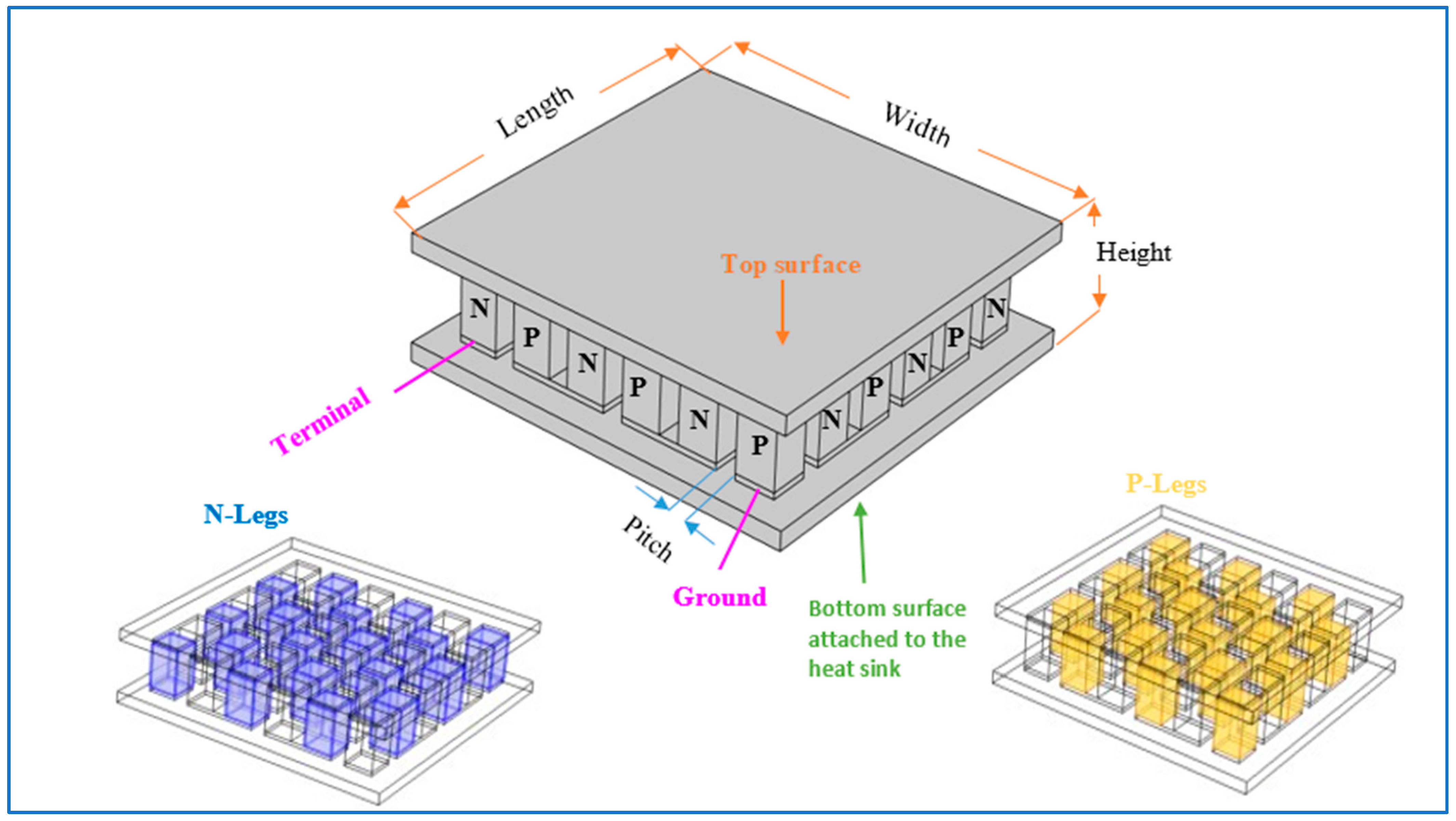
2.1. Three-Dimensional TE Model

A three-dimensional (3D) numerical model based on FA analysis has been developed using COMSOL Multiphysics 6.1 to analyze the performance of TECs. This model facilitates the prediction and optimization of both cascaded and non-cascaded TE generators (TEGs) and TECs, enabling a detailed assessment of TE technology for cooling applications. The model solves three-dimensional TE equations that provide useful information about heat transfer, electrical conductivity, and TE performance. This approach ensures precise control over the cooling parameters and thermal management, which are critical for cryosurgical applications where sub-zero temperatures are required to induce controlled tissue freezing. This approach enables a precise evaluation of heat dissipation efficiency, temperature distribution, and electrical performance in TECs under realistic operating conditions, ensuring its applicability in cryosurgical environments. To address the research focus on multi-stage optimization, the model was extended to simulate cascaded TEC configurations, optimizing the number of stages and their geometric parameters to achieve a target temperature of −70 °C (203 K) for cryosurgery. To ensure reliable simulation outcomes, a study on mesh refinement and solver configuration was conducted. The finite element mesh was refined until temperature variations (ΔT) across critical TE regions stabilized, confirming mesh independence. An efficient mesh was adopted that balanced accuracy and computational cost. COMSOL’s stationary solver was configured with a direct solver, and tolerances were adjusted for stable convergence in the multiphysics environment. A parametric sweep of input current and TE geometry was performed to capture key performance variations. This strategy enabled accurate modeling of coupled thermal and electrical behavior under cryogenic conditions. The optimization process involved iterative simulations to adjust input currents (0.5 A to 3.5 A) and stage configurations, ensuring the model accurately predicts performance under cryogenic conditions. This study goes beyond earlier research like that of Aliabadi et al. [23], which mainly looked at whether cascaded Peltier modules could work, by using detailed simulations to explore how they perform step by step when exposed to cold surgical temperatures. This enables us to identify optimal operating currents, geometry, and material interfaces through a more rigorous and spatially resolved 3D model that captures the intricate coupling of electrical and thermal transport under cryogenic constraints.

2.2. General TE Equations

The TE effect refers to the direct conversion of temperature gradients into electrical voltage and vice versa. This phenomenon serves as the operational principle behind various TE devices, including TECs used for electronic cooling and portable refrigeration systems. Unlike Joule heating, which is an irreversible process, the TE effect is inherently reversible. Historically, this effect has been classified into three distinct types based on its discovery through experimental observations by Seebeck, Peltier, and Thomson. The Seebeck effect [28,29] involves the generation of electrical voltage due to temperature differences, while the Peltier effect [30,31] describes the formation of temperature gradients as a result of an applied electrical current. Additionally, the Thomson effect [32,33] accounts for the heat generation caused by the interaction between current density and temperature gradients. The Seebeck, Peltier, and Thomson effects are fundamentally interconnected through the Thomson relations, which describe the thermodynamic relationships governing TE phenomena.
P = S T
μ = T d S d T
In TE theory, P represents the Peltier coefficient (SI unit: V), S denotes the Seebeck coefficient (SI unit: V/K), T is the temperature (SI unit: K), and μ refers to the Thomson coefficient (SI unit: V/K). These thermodynamic relationships indicate that the Seebeck, Peltier, and Thomson effects are fundamentally interconnected and can be regarded as different manifestations of the same underlying phenomenon. In this study, the Seebeck coefficient is primarily utilized, while the Peltier coefficient serves as an intermediate variable. The Thomson coefficient is not explicitly considered. In TE simulations, the key flux parameters of interest are the heat flux ( q ) and the electric current density ( J ). These quantities play a crucial role in analyzing the TE effect and understanding the performance of TE devices.
J = σ ( E S · T )
q = P J k T
Several additional parameters are relevant in the analysis of TE systems, contributing to a comprehensive understanding of their performance and efficiency.
E = V
Q = J E
Here, E represents the electric field, while Q denotes the Joule heating effect. The principles of heat energy conservation and electrical current continuity can be expressed as follows:
ρ C T t + q = Q
. J + D t = 0
In this case, only the stationary scenario is considered:
q = Q
. J = 0
The energy conversion efficiency of thermoelectric materials is typically characterized by the dimensionless figure of merit ( Z T ) [34,35], which is defined as follows:
Z T = S 2 σ T k
where ρ , C , q , J , D , σ , α , and k represent the density, heat capacity, generated or absorbed heat, current density, electric displacement, electrical conductivity, and thermal conductivity, respectively. The boundary conditions were set to simulate cryosurgical conditions, with the cold side targeting 203 K and the hot side maintained at 293 K, while a convective heat transfer coefficient of 1000 W/(m2·K) was applied to the heat sink to manage high thermal loads in multi-stage configurations. The model also incorporated a parametric sweep of input currents and stage numbers to identify optimal operating conditions for maximizing cooling efficiency. We utilized the primary element influencing TEC heat transfer equations, as outlined in our previous study, to conduct this simulation [20].

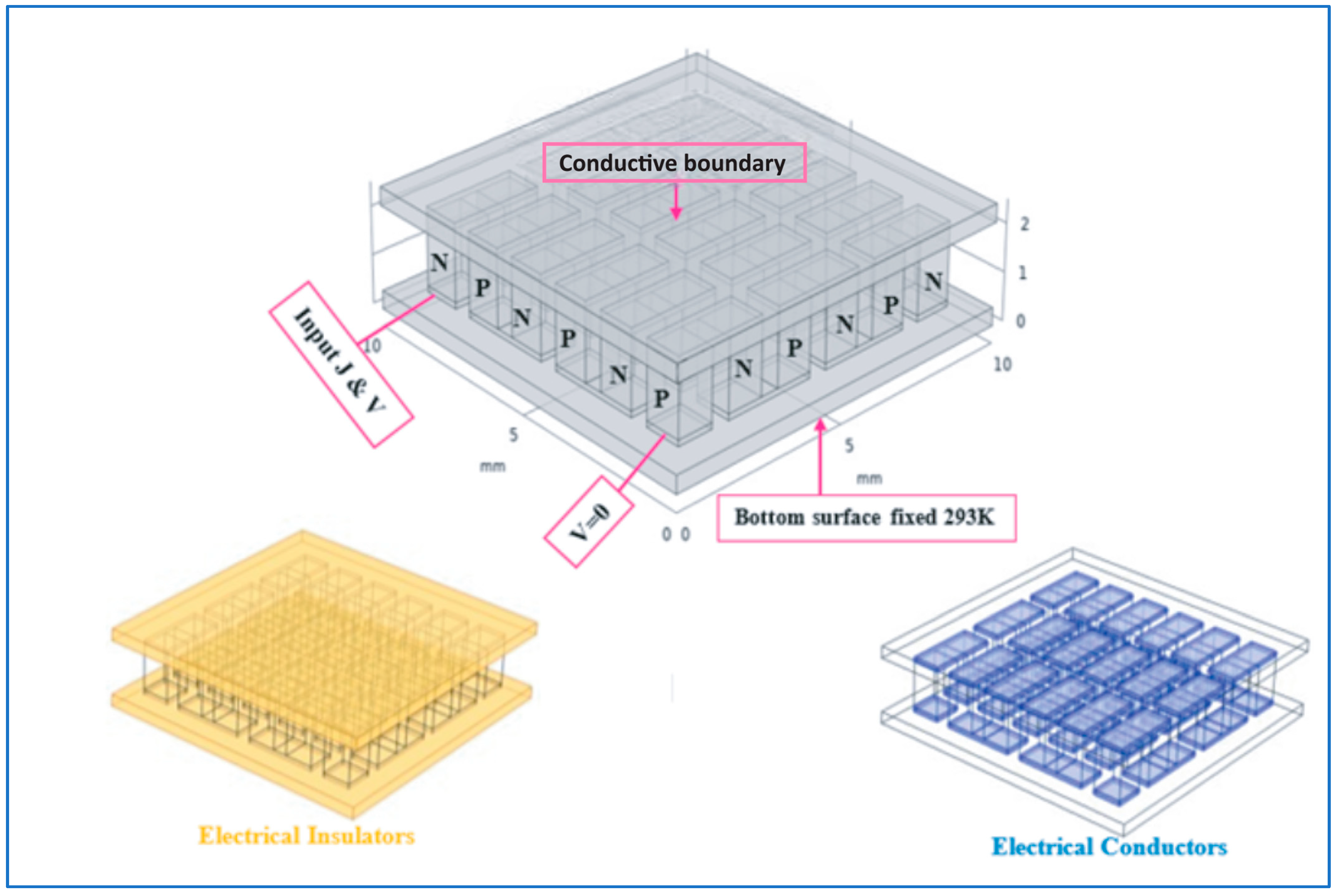
2.3. TE Material Properties and Boundary Conditions

A TEC is composed of several pairs of semiconductor elements. To achieve optimal cooling performance, the TEC structure is carefully designed to enhance heat dissipation and reduce parasitic thermal losses. The choice of Bi2Te3 as the primary TE material is based on its superior TE properties, including high Seebeck coefficient, excellent electrical conductivity, and low thermal conductivity, making it ideal for cryogenic cooling applications. Figure 1 illustrates the schematic diagram of a TEC containing 18 pairs of semiconductor elements. The assembly process involves using highly thermally insulating Al2O3 as insulators for both the upper and lower layers, which prevents heat leakage and enhances cooling performance. Silver (Ag) has superior thermal and electrical conductivity compared to Cu, potentially boosting TEC performance. Nevertheless, Cu was chosen for its affordability, availability, and ease of integration with conventional TEC fabrication methods. It is employed as the primary thermal and electrical conductor situated between the insulator layers, and Bi2Te3 is used for the p-type and n-type TE legs, as it offers the highest efficiency among commercial TE materials. The Al2O3 layers serve as electrical insulators with high thermal stability, preventing electrical short circuits while allowing efficient heat dissipation. The Cu interconnects were chosen for their superior thermal and electrical conductivity, ensuring effective heat transfer between the TE legs. In this research, a TE module consisting of 128 thermocouple TEGs, with a total of 256 legs connected electrically in series and thermally in parallel, is developed using FE methods. This configuration maximizes heat dissipation while ensuring a uniform cooling effect across the TEC module, which is essential for achieving deep tissue cooling in cryosurgical applications. The module dimensions are 25 mm × 25 mm × 2.5 mm, with p-type and n-type legs having a cross-sectional area of 1 mm × 1 mm and a thickness of 1.5 mm. The TEC leg pairs are arranged electrically in series and thermally in parallel, with Al2O3 layers having a thickness of 0.375 mm and Cu layers measuring 0.125 mm. This optimized structure minimizes thermal resistance while maximizing cooling power, ensuring efficient operation in sub-zero temperature environments. Table 1 provides the material properties used for simulation in this study.
Bi2Te3 is categorized into p-type and n-type based on carrier type, exhibiting opposite Seebeck coefficients. The p-type shows a positive Seebeck coefficient, while the n-type displays a negative one. This distinction is essential for accurately modeling TE behavior in the TEC module. Bi2Te3 was selected due to its high ZT at cryogenic temperatures, with a Seebeck coefficient that enhances cooling efficiency and a low thermal conductivity that minimizes heat backflow, making it ideal for achieving the −70 °C required for cryosurgery. Al2O3 was chosen for its high thermal stability and electrical insulation, ensuring minimal heat leakage and preventing short circuits in multi-stage setups. Cu was selected for its exceptional thermal conductivity (400 W/(m·K)), which facilitates efficient heat transfer to the heat sink, critical for maintaining stable temperature gradients in cryosurgical applications. The selection of these materials is crucial for achieving high-performance TEC operation, as they offer a balance between electrical conductivity, thermal insulation, and mechanical stability, ensuring a long lifespan and consistent performance in cryosurgical applications.
Figure 1 illustrates the schematic representation of a TE module comprising 18 TE couples, specifically designed for numerical analysis in MS TE cooling. The diagram outlines the arrangement of N-type and P-type legs interconnected via electrical terminals. Key geometric parameters such as length, width, height, and pitch are labeled to provide a detailed structural overview. Additionally, the figure highlights the top and bottom surfaces, where the latter is attached to a heat sink, serving as a crucial reference for optimizing the cooling efficiency in cryosurgical applications. The theoretical study presents a structured, physically integrated MS TEC design optimized for IR detectors, emphasizing heat flow direction, material interfaces, and stage connectivity. It illustrates both the system-level integration and thermocouple arrangement. In contrast, our numerical model focuses on device-level optimization, employing the simulation-based configuration of thermoelement dimensions, stage count, and material parameters within COMSOL.
Figure 2 presents a three-dimensional computational model of a Peltier module with dimensions of 10 × 10 × 2.5 mm3 developed using COMSOL Multiphysics for numerical simulations and performance optimization. The figure visualizes critical components, including the conductive boundary, applied input current (I), and voltage (V), with the bottom surface maintained at a constant temperature of 293 K. Furthermore, the integration of electrical insulators and conductors within the model enhances its accuracy in evaluating multi-stage TE cooling, facilitating improved thermal regulation for cryosurgical applications. The theoretical work utilizes optimal control theory to simultaneously optimize material inhomogeneity and stage-wise parameters under defined thermal constraints. This analytical framework enables a system-wide maximization of COP. Our study, however, adopts a numerical approach using finite element analysis, conducting parametric sweeps over input current and geometric variables, and refining the mesh to ensure accurate temperature and performance predictions.
To ensure accuracy and reproducibility, a mesh refinement study was conducted by varying element sizes between 0.5 mm and 0.1 mm. Convergence was achieved when the temperature deviation (ΔT) change was below 0.05 K. A 0.1 mm mesh size was selected to balance precision and computational cost. Simulations used a direct PARDISO solver with a relative tolerance of 1 × 10⁻⁶ and an absolute tolerance of 1 × 10⁻⁸ for stable convergence. Steady-state analyses included parametric sweeps of current (0.5–3.5 A, in 0.25 A steps) and leg height (1–2.5 mm, in 0.25 mm steps), enabling accurate modeling of TEC performance under varying conditions.

3. Results

This section discusses the optimization results, focused on enhancing electrical power generation and reducing chip surface temperature through cascaded and non-cascaded TECs. As previously reported, the TE module utilized in these TECs features a surface area of 10 mm × 10 mm and comprises 18 TE pairs. The numerical optimization process specifically targeted the adjustment of stage configurations, input currents, and Bi2Te3 material properties to achieve the cryogenic temperature of 203 K, ensuring precise thermal control for cryosurgical applications.

3.1. Single-Stage (SS) TEC Performance Analysis

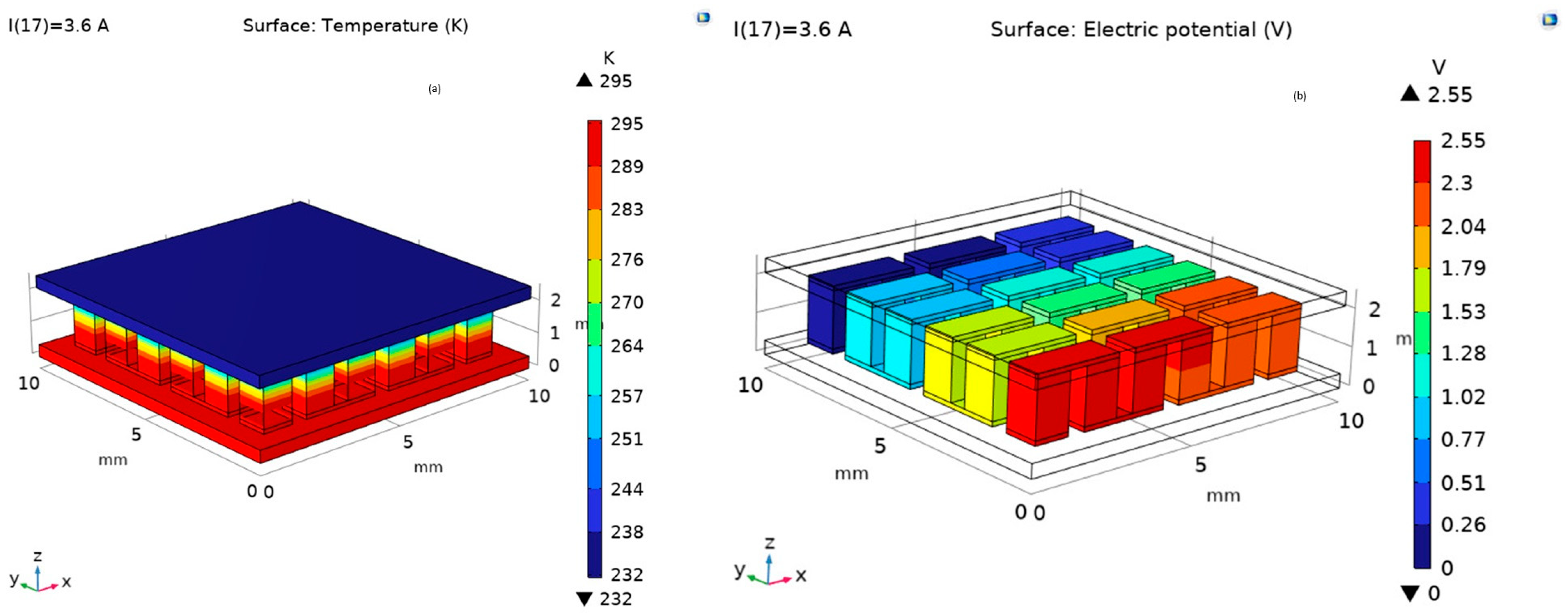
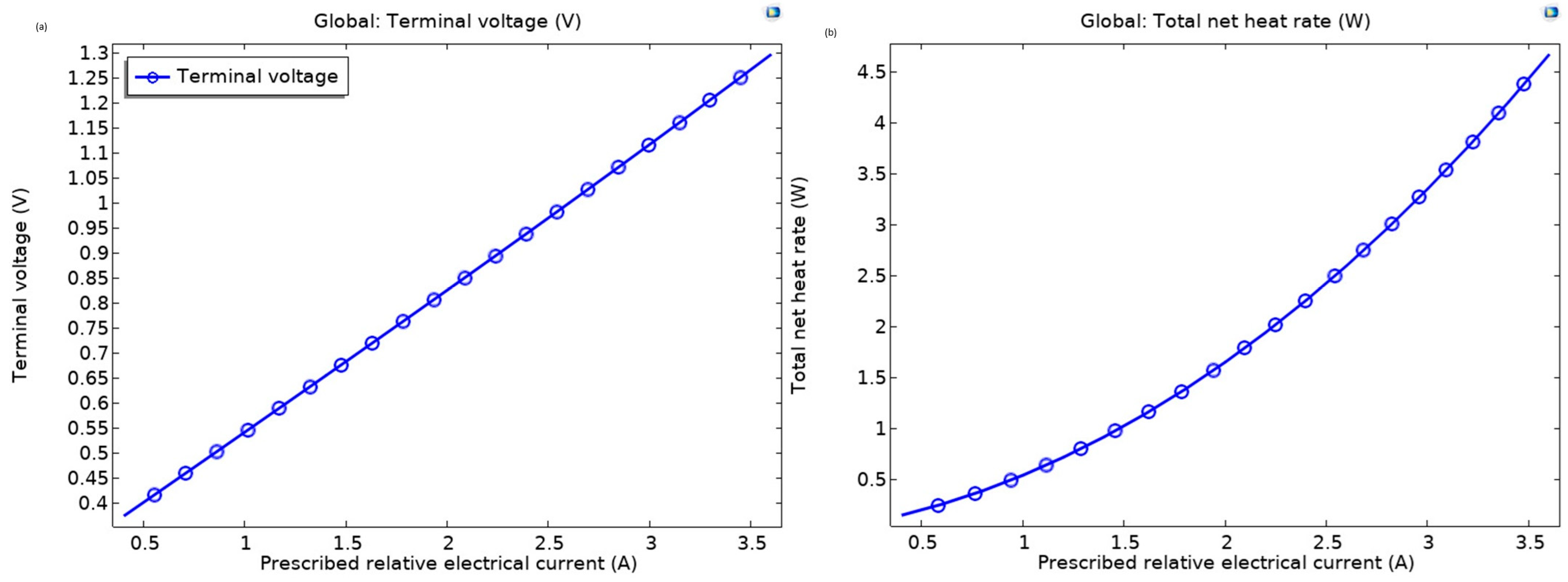
3.1.1. Thermal and Electrical Performance Analysis

Figure 3 presents a detailed numerical analysis of the thermal and electrical performance of a single-stage TEC operating under a temperature difference (ΔT) of 63 K, with implications for the optimization of multi-stage TE cooling systems tailored for cryosurgical applications. Figure 3 is divided into two subfigures: Figure 3a,b, each showcasing distinct physical properties of the TEC.
Figure 3a illustrates the surface temperature distribution across the TEC, providing a 3D representation of the thermal gradient. The color scale, ranging from 222 K to 295 K, highlights a pronounced temperature variation, with the highest temperatures observed at the base of the module (approaching 295 K) and the lowest at the top surface (near 222 K). This gradient underscores the module’s ability to efficiently absorb heat from the cold side and dissipate it at the hot side, a critical mechanism for achieving effective cooling. The spatial distribution of temperature suggests robust heat transfer capabilities, yet the maximum ΔT of 63 K indicates a limitation in reaching the ultra-low temperatures required for cryosurgical procedures, such as cancer tissue ablation. This limitation is consistent with findings by Solana et al. [36], who reported that SS Bi2Te3-based TECs typically achieve ΔT values below 70 K, necessitating multi-stage designs to reach cryogenic temperatures like 203 K for cryosurgical applications. Figure 3b depicts the surface electric potential distribution under open-circuit conditions, with a color scale ranging from 0 V to 2.54 V. The visualization reveals a systematic variation in electric potential across the TE elements, with the highest potential concentrated at the hot side and a gradual decline toward the cold side. This pattern aligns with the Seebeck effect, where temperature differences induce voltage generation, providing insight into the electrical performance of the TEC. The data suggest that while the SS configuration generates a measurable voltage, it falls short of supporting the sub-zero temperatures necessary for advanced cryosurgical applications. This voltage distribution aligns with observations by Cao et al. [37], who noted that Bi2Te3-based TECs exhibit systematic potential gradients, but SS designs require optimization to enhance electrical performance for biomedical applications. Collectively, these findings emphasize the inherent constraints of a single-stage TEC in achieving the cryogenic temperatures essential for effective cryosurgery. The observed thermal and electrical profiles highlight the need for a multi-stage TE cooling system, which could enhance cooling efficiency and enable the precise temperature control required for ablating cancerous tissues. This analysis serves as a foundational step toward optimizing the design and performance of multi-stage TECs for biomedical applications. Specifically, the results underscore the need for the numerical optimization of stage configurations and Bi2Te3 material properties to achieve the target temperature of 203 K, as required for effective cryosurgical interventions. The numerical optimization process involved adjusting the input current and leg geometry to maximize ΔT, revealing that Bi2Te3’s high Seebeck coefficient was crucial for the observed voltage generation, though insufficient for cryosurgical needs in an SS setup.

3.1.2. Comparative Analysis of Temperature Difference

Figure 4 illustrates a comprehensive evaluation of the ΔT in an SS TEC module for the numerical analysis and optimization of multi-stage TE cooling for cryosurgical applications. It is divided into two subplots: Figure 4a illustrates the relationship between ΔT and input current (I in amperes), and Figure 4b depicts the transient response of ΔT over time (in seconds).
In Figure 4a, the FEs 3D Model (blue curve) and Lumped Model (green dashed curve with data points) show a rising ΔT with increasing current, peaking at approximately 65–70 K, with the 3D model slightly outperforming the lumped approach, reflecting its ability to capture intricate thermal distributions. This observation aligns with recent findings that emphasize the importance of accurate thermal modeling in optimizing TEC performance for cryosurgical applications [38]. Figure 4b demonstrates the temporal evolution of ΔT, with both models converging toward a stable maximum of around 70 K within 20 s, highlighting the rapid thermal stabilization critical for cryosurgical precision. These findings underscore the Finite Elements 3D Model’s enhanced accuracy in simulating complex thermal dynamics, offering significant implications for optimizing SS TECs and informing the design of MS systems for effective cryosurgical interventions. The optimization process identified an optimal current of 3.0 A to balance ΔT and Joule heating, indicating that further increases in current beyond this point reduced efficiency due to thermal losses, necessitating multi-stage designs to achieve the target of 203 K. The temperature-dependent Seebeck coefficient of Bi2Te3 is crucial for performance limits, as it increases at lower temperatures, enhancing ΔT at low currents. However, this advantage diminishes at higher currents due to increased Joule heating. The model also neglects the Thomson effect, which contributes to heat generation and restricts ΔT under high current conditions. This highlights the need for compact device integration using materials with high thermal conductivity and optimized heat sink designs with larger surface areas to manage heat load effectively in cryosurgical applications.

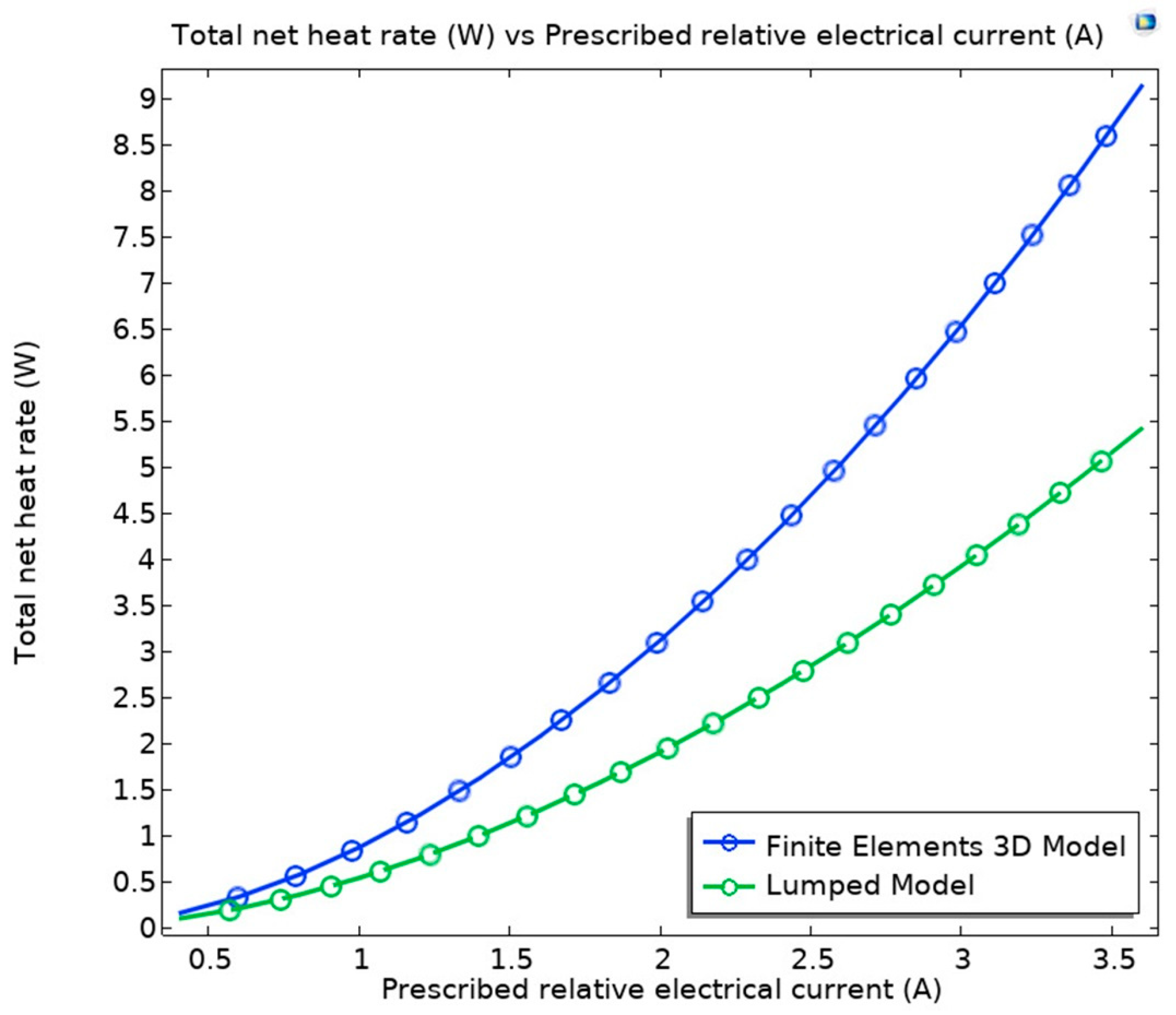
3.1.3. Electrical and Thermal Performance Characteristics

Figure 5 illustrates a detailed assessment of the electrical and thermal performance characteristics of a single-stage TEC module for the numerical analysis and optimization of MS TEC cooling systems tailored for cryosurgical applications. The figure comprises two subplots: Figure 5a depicts the variation of terminal voltage (in volts) as a function of prescribed electrical current, and Figure 5b illustrates the corresponding total net heat rate (in watts) with respect to the same input current range.
In Figure 5a, the terminal voltage exhibits a linear increase from approximately 0.6 V to 2.4 V as the current rises from 0.5 A to 3.5 A, reflecting the direct proportionality between voltage and current as dictated by the TEC’s electrical resistance and Seebeck effects. Figure 5b reveals a similar linear trend for the total net heat rate, escalating from around 1 W to 8 W over the same current range, highlighting the enhanced heat absorption capacity of the TEC with increasing electrical input. These findings align with recent advancements in TEC optimization, which underscore the importance of balancing electrical power consumption and thermal performance for cryosurgical applications [39]. This analysis is instrumental in optimizing the design of MS TEC systems, ensuring effective cooling performance for cryosurgical procedures where precise thermal management is essential for successful tissue preservation and ablation. The numerical optimization revealed that Bi2Te3’s high electrical conductivity contributed to the linear voltage increase, but the heat rate’s rapid rise at higher currents suggests thermal inefficiencies, further supporting the need for MS configurations to manage heat loads effectively. The temperature sensitivity of the Seebeck coefficient increases voltage output at lower temperatures but causes more Joule heating at higher currents, reducing thermal efficiency. Additionally, the decreasing thermal conductivity of Bi2Te3 with temperature limits heat dissipation, worsening this tradeoff. The model’s exclusion of the Thomson effect neglects a source of internal heat generation, affecting thermal prediction accuracy. To address these limitations, the device should use thermally insulating materials to minimize heat loss and advanced heat-sink systems with active cooling to manage thermal loads, ensuring reliable performance in cryosurgical settings.

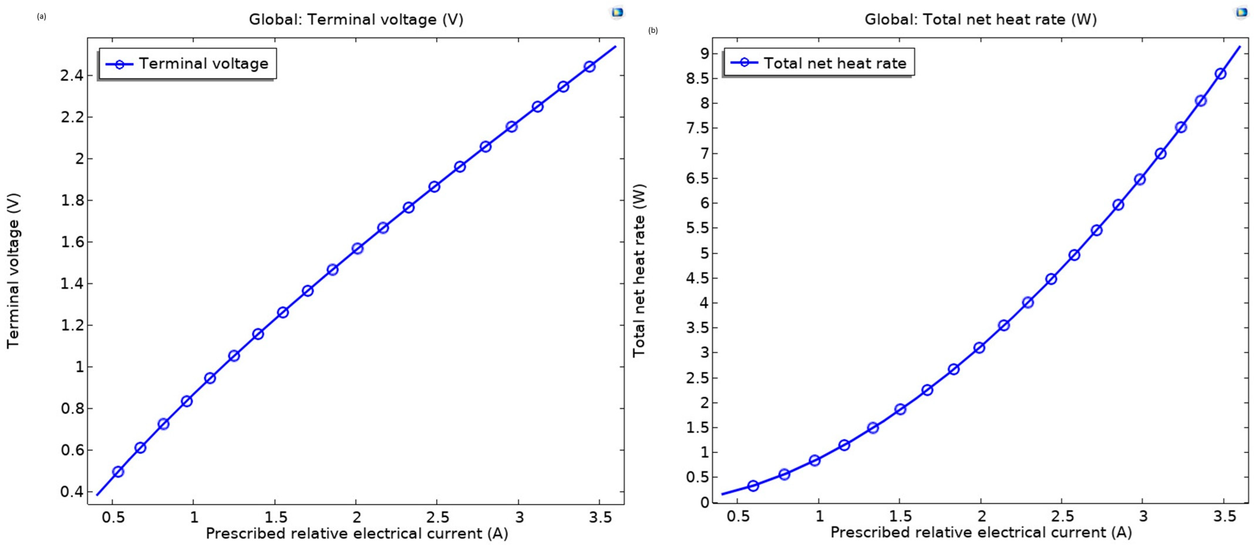
3.1.4. Electric Power Consumption Evaluation

Figure 6 presents an in-depth analysis of the electric power consumption of an SS TEC module as a function of input current for the numerical analysis and optimization of multi-stage TE cooling systems aimed at cryosurgical applications. This comparison is crucial for understanding the potential efficiency of TEC systems in medical applications, particularly in cryosurgery, where precise thermal management is essential. The graph compares two simulation approaches: the FEs 3D Model, depicted by a continuous blue curve, and the Lumped Model, represented by a green dashed curve with circular data points. The results demonstrate a near-parabolic increase in electric power with increasing current, ranging from approximately 0.5 W at 0.5 A to 8.5 W at 3.5 A for the FEs 3D Model, while the Lumped Model shows a slightly lower power consumption, peaking at around 7.5 W at the same current. This trend is consistent with the results of Hao et al. [40], where the optimization of TE systems showed a trade-off between power consumption and thermal performance, specifically when varying parameters such as the working current. This divergence highlights the Finite Elements 3D Model’s ability to account for detailed electrical and thermal interactions within the TEC, providing a more accurate representation of power requirements.
In contrast, the Lumped Model, while computationally efficient, may not capture all of the nuanced thermal dynamics observed in the more complex 3D model. The observed trend underscores the trade-off between cooling performance and energy efficiency, a critical consideration for cryosurgical applications where minimizing power consumption while achieving low temperatures is essential. These findings offer valuable insights for optimizing the electrical design of SS TECs, paving the way for the development of energy-efficient MS systems tailored for precise thermal management in cryosurgical procedures. This can guide the design of more efficient cooling systems, which could be scaled up for medical applications requiring multi-stage TE cooling, where Bi2Te3 plays a key role in maximizing efficiency. The optimization process identified an optimal operating current of 2.5 A to minimize power consumption while maintaining a ΔT of 65 K, highlighting the need for multi-stage designs to reduce energy demands while achieving the required cryogenic temperatures. The variation of the Seebeck coefficient with temperature improves power output at low currents but increases Joule heating at higher currents. Temperature-dependent thermal conductivity limits heat flow, leading to a nonlinear power response. Omitting the Thomson effect from the model underestimates internal heat generation, which impacts power consumption estimates. Effective thermal management is crucial, incorporating thermal barrier layers in packaging and heat sinks with advanced fin geometries to ensure efficient heat removal, thereby supporting stable operation in cryosurgical applications.

3.1.5. Geometry and Performance Evaluation

Figure 7 presents the numerical simulation results of an SS TEC module. These results are used to study and improve multi-stage thermoelectric cooling systems used in cryosurgery. The figure illustrates the temperature distribution across the 10 mm × 10 mm × 2.5 mm module, with Bi2Te3 as the TE material, showing a gradient from 323.15 K at the hot side to 245.88 K at the cold side.
Key geometry parameters include 18 TE elements, a leg cross-section of 0.001 m × 0.001 m, and a ceramic thickness of 3.75 × 10⁻⁴ m. Performance metrics indicate a maximum temperature difference of 73.27 K and a maximum voltage of 2.82 V, with a resistance of 0.89 Ω and a ZT of 0.002377 1/K. These results are in close agreement with the findings of our previous study that reported a maximum temperature difference of 73.94 K and similar electrical characteristics for a Bi2Te3-based TEC, confirming the accuracy of the simulation and the effectiveness of Bi2Te3 in achieving high cooling performance [20]. These findings highlight the cooling potential of the SS TEC, providing a baseline for optimizing MS configurations to achieve the ultra-low temperatures required for cryosurgery. The numerical optimization of leg geometry revealed that the 1 mm × 1 mm cross-section maximized heat transfer efficiency, while Bi2Te3’s low thermal conductivity ensured the observed temperature gradient, though insufficient for cryosurgical needs without additional stages.

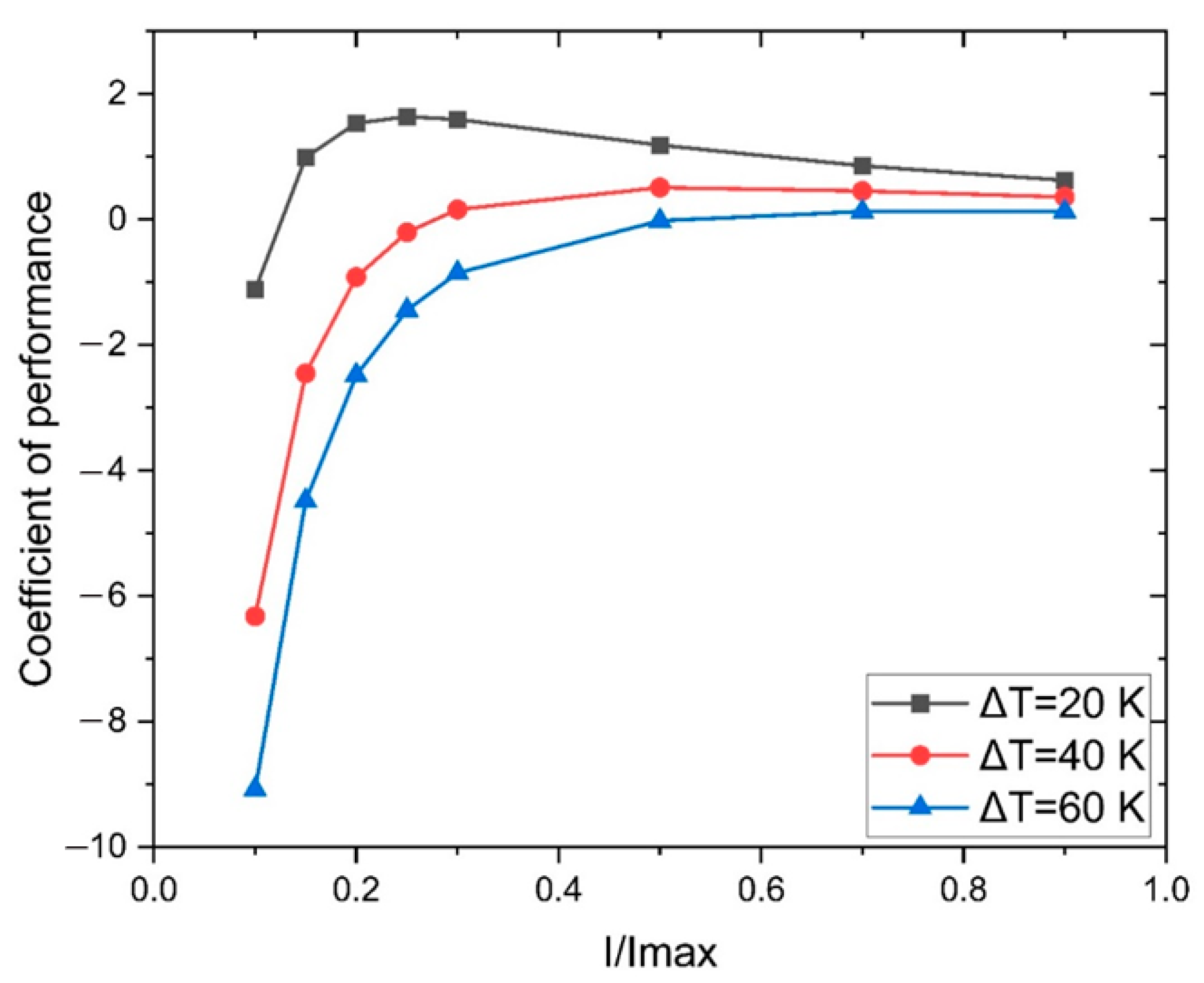
3.1.6. Coefficient of Performance (COP) Analysis

Figure 8 describes an analysis of the COP for a single-stage TEC under varying current-to-maximum current ratios (I/Imax) for the numerical analysis and optimization of MS TE cooling systems for cryosurgical applications. The figure compares COP across ΔT of 20 K, 40 K, and 60 K, with the COP peaking at 1.8393, 0.5963, and 0.12962, respectively, at optimal current ratios. The blue, green, and red curves illustrate a decline in COP with increasing ΔT, reflecting the trade-off between cooling efficiency and temperature gradient. This trend is consistent with the findings of Venkatesan et al. [41], where a decrease in COP was observed as ΔT increased, highlighting the inherent limitations of single-stage TECs in maintaining efficiency under large temperature gradients.
The theoretical results show that reducing contact resistance and using insulating plates and functionally graded materials can boost COP by 1.5–2.5 times compared to commercial modules [42]. Our numerical results also reflect improved performance under optimized geometry and operating conditions, though possibly without explicitly modeling functionally graded materials or precise contact resistances. These results further emphasize the necessity for multi-stage TEC configurations to achieve the required cryogenic temperatures for medical applications. The optimization process identified an optimal I/Imax ratio of 0.6 for a ΔT of 20 K to maximize COP, indicating that Bi2Te3’s TE properties are best utilized at lower temperature differences in SS setups, further justifying the need for MS designs.

3.1.7. Limitations and MS Design Implications

The inherent limitation of single-stage Peltier devices, which achieve a maximum temperature difference of approximately 70 K, restricts their ability to reach the ultra-low temperatures necessary for effective cryosurgical procedures, such as cancer tissue ablation at −70 °C (203 K). To overcome this challenge, MS Peltier devices have been developed, stacking multiple TE modules to achieve higher temperature differentials. For instance, a two-stage module can achieve a temperature difference of up to 93 °C, while a five-stage module can reach up to 128 °C. This cascading approach enhances cooling capacity, making multi-stage Peltier devices suitable for applications requiring precise thermal control, such as cryosurgery. However, implementing MS systems necessitates the meticulous optimization of stage configuration, material properties, and electrical inputs to maximize efficiency and ensure precise thermal control. This careful design process is crucial for achieving the ultra-low temperatures critical for cryosurgery, thereby paving the way for improved therapeutic outcomes in cancer treatment. Our findings align with Oktaviani et al. [43], who demonstrated that MS TE systems significantly enhance cooling capacity, enabling rapid temperature reduction essential for cryosurgery. Their study supports the need for MS configurations to achieve ultra-low temperatures, offering improved efficiency and cost-effectiveness in cancer treatment. The numerical optimization process confirmed that a three-stage configuration was necessary to achieve the target of 203 K, with Bi2Te3’s high ZT playing a critical role in enhancing cooling efficiency across stages.

3.2. Multi-Stage (MS) TEC Performance Analysis

3.2.1. Spatial Distribution Analysis

Figure 9 presents a detailed spatial distribution analysis of an MS TEC module under maximum operating conditions for the numerical analysis and optimization of MS TE cooling systems designed for cryosurgical applications. The figure is divided into two subplots: Figure 9a illustrates the surface temperature distribution across the module, and Figure 9b depicts the electric potential distribution within the same structure.
In Figure 9a, the temperature profile ranges from 220 K at the cold end to 294 K at the hot end, with a gradient across the 10 mm × 10 mm × 5 mm module, indicating effective heat transfer through the stacked stages. Figure 9b shows the electric potential varying from 0 V at the ground to 1.3 V at the terminal, with a uniform increase across the TE elements, reflecting the applied voltage distribution that drives the cooling process. These results highlight the MS TEC’s capability to achieve significant temperature reductions, surpassing the limitations of SS devices, which is critical for reaching the −70 °C (203 K) required for cancer tissue ablation. The observed thermal and electrical gradients provide valuable insights for optimizing stage design and material selection, ensuring enhanced cooling efficiency and precision in cryosurgical interventions. This can be similar to Cheng et al.’s outcomes [44], where multi-stage TE systems demonstrated superior performance at large temperature differences, highlighting their effectiveness over SS configurations in extreme cooling applications. The numerical optimization of stage numbers revealed that a three-stage configuration, combined with Bi2Te3’s low thermal conductivity, was essential for achieving the 220 K cold-end temperature, meeting the cryosurgical requirement of 203 K.

3.2.2. Comparative Analysis of Temperature Difference vs. Input Current

Figure 10 presents a comparative evaluation of the ΔT as a function of I for an MS TE cooling system for enhanced cryosurgical applications. The graph combines two numerical models: Figure 10a, the FEs 3D Model (solid blue curve), and Figure 10b, the Lumped Model (green dashed curve with circular data points), highlighting their performance in predicting ΔT across a current range of 0.5 A to 3.5 A.
The MS TEC configuration, consisting of three cascaded stages, demonstrates a significant improvement over single-stage systems, with the FEs 3D Model predicting a peak ΔT of approximately 90 K at 3.5 A, compared to 85 K for the Lumped Model. This enhanced ΔT enables the system to achieve cold-end temperatures as low as 203 K (−70 °C), which is critical for effective cancer tissue ablation in cryosurgery. The 3D model’s slight outperformance reflects its ability to capture detailed spatial thermal gradients across the stacked stages, providing a more accurate representation of heat transfer dynamics in the Bi2Te3-based TEC. The rapid increase in ΔT with current underscores the potential of MS designs to meet the stringent thermal requirements of cryosurgical procedures, while the close agreement between the two models validates the reliability of the numerical optimization approach. These results are in line with recent studies that have demonstrated the efficacy of multi-stage TECs in achieving substantial temperature differences, thereby enhancing cooling performance in medical applications [45]. The optimization process identified an optimal current of 3.0 A for the three-stage setup, balancing ΔT and power consumption, with Bi2Te3’s high Seebeck coefficient enabling the significant temperature reduction observed.

3.2.3. Electrical and Thermal Performance Characteristics

Figure 11 presents an analysis of the electrical and thermal performance of an MS TEC module for the numerical analysis and optimization of multi-stage TE cooling systems for cryosurgical applications. The figure includes two subplots: Figure 11a shows the terminal voltage increasing linearly from 0.4 V to 1.25 V as the prescribed electrical current rises from 0.5 A to 3.5 A, reflecting the electrical demand of the multi-stage configuration. Figure 11b illustrates the total net heat rate, which exhibits a parabolic increase from 0.5 W to 4 W over the same current range, indicating enhanced heat absorption capacity with higher electrical input.
These results highlight the multi-stage TEC’s ability to manage increased thermal loads, a critical factor for achieving the ultra-low temperatures (e.g., −70 °C or 203 K) required for cancer tissue ablation. These findings align with the results of Karimi et al. [46], who demonstrated that multi-stage TECs exhibit enhanced heat absorption capacity and increased thermal load management, with performance improving as the number of stages increases. This supports the ability of multi-stage TECs to achieve the ultra-low temperatures required for cryosurgical applications. The numerical optimization process showed that Bi2Te3’s high electrical conductivity enabled the linear voltage increase across stages, while the parabolic heat rate increase indicates efficient heat management, crucial for maintaining stable cryogenic temperatures during cryosurgery.

3.2.4. Comparative Analysis of Electric Power Consumption

Figure 12 describes a comparative evaluation of electric power consumption in an MS TEC module for the numerical analysis and optimization of multi-stage TE cooling systems for cryosurgical applications. The graph contrasts the Finite Elements 3D Model (blue curve) and the Lumped Model (green dashed curve with data points), showing a parabolic increase in power from 0.5 W to 5.5 W as the input current rises from 0.5 A to 3.5 A. The FEs 3D Model consistently predicts higher power consumption, reflecting its detailed accounting of electrical and thermal interactions across multiple stages. These findings highlight the energy demands of MS TECs, providing critical insights for optimizing power efficiency while achieving the low temperatures required for cryosurgical procedures. Understanding the power consumption characteristics is essential for designing TEC systems that are both effective and energy-efficient, thereby enhancing their practicality in clinical settings. Recent advancements in TEC materials, such as the development of (Bi,Sb)2Te3 alloys with improved TE and mechanical performance, offer promising avenues for enhancing the efficiency and durability of TEC systems [47]. The optimization process identified an optimal operating current of 2.8 A for the multi-stage setup to minimize power consumption while achieving a ΔT of 90 K, demonstrating the energy efficiency benefits of multi-stage designs for cryosurgical applications.

3.2.5. Implications for Cryosurgical Applications

The comprehensive analysis of the MS TEC’s spatial distribution, temperature difference, electrical characteristics, and power consumption underscores its potential in cryosurgical applications. Achieving and maintaining ultra-low temperatures is crucial for effective tissue ablation, and the multi-stage TEC’s performance metrics align with these clinical requirements. Future research should focus on integrating these TEC systems into cryosurgical devices, optimizing their design for specific medical applications, and conducting in vivo studies to validate their efficacy and safety. The numerical optimization process confirmed that the MS TEC, leveraging Bi2Te3’s superior TE properties, can achieve the required 203 K, making it a viable alternative to traditional cryogenic fluids for precise and controlled tissue ablation in cryosurgery. Both studies conclude that minimizing contact and thermal interface resistances is essential for enhancing TEC efficiency. While the theoretical model provides a system-level blueprint for designing high-performance TECs using optimal control, our numerical analysis offers practical insights into device optimization, making both approaches complementary in advancing TEC design for cryogenic and IR applications.

4. Conclusions

This study demonstrates that optimized multi-stage thermoelectric cooling systems using Bi2Te3 offer a viable, energy-efficient alternative to conventional cryogenic methods for cryosurgery. The multi-stage design achieved a cold-side temperature of −70 °C, a temperature difference of 90 K, and a cooling power of 4.0 W—exceeding the performance of single-stage systems. Numerical analysis confirmed that the careful optimization of current, geometry, and materials significantly enhances cooling efficiency. These results highlight the potential of compact TE devices for precise biomedical cooling. Future research will explore advanced nanomaterials and hybrid systems to further improve clinical performance.

Author Contributions

Conceptualization, M.R.A.B.; methodology, A.K.; software, E.Y.S.; formal analysis, M.K.H.; investigation, M.K.H.; resources, H.B.; data curation, M.R.A.B.; writing—original draft preparation, A.K.; writing—review and editing, M.R.A.B. and H.M. All authors have read and agreed to the published version of the manuscript.

Funding

This research received no external funding.

Data Availability Statement

The data presented in this study are available on request from the corresponding author.

Acknowledgments

The authors would like to express their sincere gratitude to the Laboratory of Materials, Waves, Energy, and Environment (MEGCE Group), Department of Physics, Faculty of Sciences, Mohamed I University, Oujda 60000, Morocco, and the Department of Electrical and Electronic Engineering, Teesta University, Rangpur, Bangladesh, for their valuable support and collaboration.

Conflicts of Interest

There are no competing interests between the authors and the publishing of this work. There are no other journals that have published this paper.

References

  1. Zabek, D.; Morini, F. Solid state generators and energy harvesters for waste heat recovery and thermal energy harvesting. Therm. Sci. Eng. Prog. 2019, 9, 235–247. [Google Scholar] [CrossRef]
  2. Wang, C. Recent progress in thermoelectric materials, devices and applications. Kexue Tongbao/Chin. Sci. Bull. 2021, 66, 2024–2032. [Google Scholar] [CrossRef]
  3. Ochieng, A.O.; Megahed, T.F.; Ookawara, S.; Hassan, H. Comprehensive review in waste heat recovery in different thermal energy-consuming processes using thermoelectric generators for electrical power generation. Process Saf. Environ. Prot. 2022, 162, 134–154. [Google Scholar] [CrossRef]
  4. Baskaran, P.; Rajasekar, M. Recent trends and future perspectives of thermoelectric materials and their applications. RSC Adv. 2024, 14, 21706–21744. [Google Scholar] [CrossRef] [PubMed]
  5. Wang, J.; Wang, J.B.; Long, Z.Y.; Zhu, T.; Li, Z.S.; Jiang, Z.C.; Liu, J. Design and application of a cooling device based on peltier effect coupled with electrohydrodynamics. Int. J. Therm. Sci. 2021, 162, 106761. [Google Scholar] [CrossRef]
  6. Hafid, M.; Lacroix, M. Fast inverse prediction of the freezing front in cryosurgery. J. Therm. Biol. 2017, 69, 13–22. [Google Scholar] [CrossRef]
  7. Zohuri, B. Cryogenics and Liquid Hydrogen Storage. In Hydrogen Energy: Challenges and Solutions for a Cleaner Future; Springer International Publishing: Cham, Switzerland, 2019; pp. 121–139. [Google Scholar] [CrossRef]
  8. Mahek, M.K.; Ramadan, M.; Dol, S.S.B.; Ghazal, M.; Alkhedher, M. A comprehensive review of thermoelectric cooling technologies for enhanced thermal management in lithium-ion battery systems. Heliyon 2024, 10, e40649. [Google Scholar] [CrossRef]
  9. Sun, Q.; Du, C.; Chen, G. Thermoelectric materials and devices: Applications in enhancing building energy conversion and efficiency. Adv. Nanocompos. 2025, 2, 15–31. [Google Scholar] [CrossRef]
  10. Twaha, S.; Zhu, J.; Yan, Y.; Li, B. A comprehensive review of thermoelectric technology: Materials, applications, modelling and performance improvement. Renew. Sustain. Energy Rev. 2016, 65, 698–726. [Google Scholar] [CrossRef]
  11. Mamur, H.; Bhuiyan, M.R.A.; Korkmaz, F.; Nil, M. A review on bismuth telluride (Bi2Te3) nanostructure for thermoelectric applications. Renew. Sustain. Energy Rev. 2018, 82, 4159–4169. [Google Scholar] [CrossRef]
  12. Li, Y.; Li, W.; Han, T.; Zheng, X.; Li, J.; Li, B.; Fan, S.; Qiu, C.-W. Transforming heat transfer with thermal metamaterials and devices. Nat. Rev. Mater. 2021, 6, 488–507. [Google Scholar] [CrossRef]
  13. Guclu, T.; Cuce, E. Thermoelectric Coolers (TECs): From Theory to Practice. J. Electron. Mater. 2019, 48, 211–230. [Google Scholar] [CrossRef]
  14. Najafi, H.; Woodbury, K.A. Optimization of a cooling system based on Peltier effect for photovoltaic cells. Sol. Energy 2013, 91, 152–160. [Google Scholar] [CrossRef]
  15. Astrain, D.; Vián, J.G.; Albizua, J. Computational model for refrigerators based on Peltier effect application. Appl. Therm. Eng. 2005, 25, 3149–3162. [Google Scholar] [CrossRef]
  16. Witting, I.T.; Chasapis, T.C.; Ricci, F.; Peters, M.; Heinz, N.A.; Hautier, G.; Snyder, G.J. The Thermoelectric Properties of Bismuth Telluride. Adv. Electron. Mater. 2019, 5, 1800904. [Google Scholar] [CrossRef]
  17. Liu, K.; Li, Y.Z.; Wu, Y.X.; Ying, P.J.; He, R.; Fu, C.G.; Zhang, Y.; Zhu, T.J. Application requirements and design strategies of Bi 2 Te 3 -based thermoelectric devices for low-quality thermal energy. cMat 2024, 1, e11. [Google Scholar] [CrossRef]
  18. Bhuiyan, M.R.A.; Korucu, H.; Mamur, H.; Haque, M.M. Growth and characterization of Bi2Te2.70Se0.30 nanostructured materials by using a cost-effective chemical solution route. J. Alloy. Metall. Syst. 2023, 4, 100032. [Google Scholar] [CrossRef]
  19. Kherkhar, A.; Chiba, Y.; Tlemçani, A.; Mamur, H. Thermal investigation of a thermoelectric cooler based on Arduino and PID control approach. Case Stud. Therm. Eng. 2022, 36, 102249. [Google Scholar] [CrossRef]
  20. Hasan, M.K.; Haque, M.M.; Üstüner, M.A.; Mamur, H.; Bhuiyan, M.R.A. Optimizing the performance of Bi2Te3 TECs through numerical simulations using COMSOL multiphysics. J. Alloy. Metall. Syst. 2024, 5, 100056. [Google Scholar] [CrossRef]
  21. Jaziri, N.; Boughamoura, A.; Müller, J.; Mezghani, B.; Tounsi, F.; Ismail, M. A comprehensive review of Thermoelectric Generators: Technologies and common applications. Energy Rep. 2020, 6, 264–287. [Google Scholar] [CrossRef]
  22. Zhang, J.Y.; Xia, C.; Wang, H.F.; Tang, C. Recent advances in electrocatalytic oxygen reduction for on-site hydrogen peroxide synthesis in acidic media. J. Energy Chem. 2022, 67, 432–450. [Google Scholar] [CrossRef]
  23. Aliabadi, P.; Mahmoud, S.; AL-Dadah, R.K. Simulation of Cascaded Thermoelectric Devices for Cryogenic Medical Treatment. In Proceedings of the 2014 COMSOL Conference in Cambridge; 2014; pp. 1–4. [Google Scholar]
  24. Chen, L.; Liu, R.; Shi, X. Thermoelectric Materials and Devices; Elsevier: Amsterdam, The Netherlands, 2020. [Google Scholar] [CrossRef]
  25. Hu, B.; Shi, X.L.; Zou, J.; Chen, Z.G. Thermoelectrics for medical applications: Progress, challenges, and perspectives. Chem. Eng. J. 2022, 437, 135268. [Google Scholar] [CrossRef]
  26. Whaley, D.; Damyar, K.; Witek, R.P.; Mendoza, A.; Alexander, M.; Lakey, J.R.T. Cryopreservation: An Overview of Principles and Cell-Specific Considerations. Cell Transplant. 2021, 30, 1–12. [Google Scholar] [CrossRef] [PubMed]
  27. Zaferani, S.H.; Sams, M.W.; Ghomashchi, R.; Chen, Z.G. Thermoelectric coolers as thermal management systems for medical applications: Design, optimization, and advancement. Nano Energy 2021, 90, 106572. [Google Scholar] [CrossRef]
  28. Tan, G.; Zhao, L.-D.; Kanatzidis, M.G. Rationally Designing High-Performance Bulk Thermoelectric Materials. Chem. Rev. 2016, 116, 12123–12149. [Google Scholar] [CrossRef]
  29. Kroon, R.; Mengistie, D.A.; Kiefer, D.; Hynynen, J.; Ryan, J.D.; Yu, L.; Müller, C. Thermoelectric plastics: From design to synthesis, processing and structure-property relationships. Chem. Soc. Rev. 2016, 45, 6147–6164. [Google Scholar] [CrossRef]
  30. Amengual, A.; Isalgue, A.; Marco, F.; Tachoire, H.; Torra, V.; Torra, V.R. Automatic equipment with improved performances (ATD and DSC) in shape memory alloys studies. J. Therm. Anal. 1992, 38, 583–592. [Google Scholar] [CrossRef]
  31. Drebushchak, V.A. The Peltier effect. J. Therm. Anal. Calorim. 2008, 91, 311–315. [Google Scholar] [CrossRef]
  32. Modak, R.; Murata, M.; Hou, D.; Miura, A.; Iguchi, R.; Xu, B.; Guo, R.; Shiomi, J.; Sakuraba, Y.; Uchida, K.I. Phase-transition-induced giant Thomson effect for thermoelectric cooling. Appl. Phys. Rev. 2022, 9, 011414. [Google Scholar] [CrossRef]
  33. Thomson, W. 4. On a Mechanical Theory of Thermo-Electric Currents. Proc. R. Soc. Edinb. 1857, 3, 91–98. [Google Scholar] [CrossRef]
  34. Snyder, G.J.; Snyder, A.H. Figure of merit ZT of a thermoelectric device defined from materials properties. Energy Environ. Sci. 2017, 10, 2280–2283. [Google Scholar] [CrossRef]
  35. Abol-Fotouh, D.; Dörling, B.; Zapata-Arteaga, O.; Rodríguez-Martínez, X.; Gómez, A.; Reparaz, J.S.; Laromaine, A.; Roig, A.; Campoy-Quiles, M. Farming thermoelectric paper. Energy Environ. Sci. 2019, 12, 716–726. [Google Scholar] [CrossRef] [PubMed]
  36. Cervino-Solana, P.; Ramirez-Peral, M.J.; Martín-González, M.S.; Caballero-Calero, O. Thermoelectric bismuth telluride nanostructures fabricated by electrodeposition within flexible templates. Heliyon 2024, 10, e36114. [Google Scholar] [CrossRef] [PubMed]
  37. Cao, T.; Shi, X.L.; Li, M.; Hu, B.; Chen, W.; Liu, W.D.; Lyu, W.; MacLeod, J.; Chen, Z.G. Advances in bismuth-telluride-based thermoelectric devices: Progress and challenges. eScience 2023, 3, 100122. [Google Scholar] [CrossRef]
  38. Kishore, R.A.; Kumar, P.; Sanghadasa, M.; Priya, S. Taguchi optimization of bismuth-telluride based thermoelectric cooler. J. Appl. Phys. 2017, 122, 25109. [Google Scholar] [CrossRef]
  39. Lu, T.; Zhang, X.; Zhang, J.; Ning, P.; Li, Y.; Niu, P. Multi-objective optimization of thermoelectric cooler using genetic algorithms. AIP Adv. 2019, 9, 095105. [Google Scholar] [CrossRef]
  40. Hao, J.; Qiu, H.; Ren, J.; Ge, Z.; Chen, Q.; Du, X. Multi-parameters analysis and optimization of a typical thermoelectric cooler based on the dimensional analysis and experimental validation. Energy 2020, 205, 118043. [Google Scholar] [CrossRef]
  41. Venkatesan, K.; Venkataramanan, M. Experimental and Simulation Studies on Thermoelectric Cooler: A Performance Study Approach. Int. J. Thermophys. 2020, 41, 38. [Google Scholar] [CrossRef]
  42. Vikhor, L.; Lysko, V.; Kotsur, M.; Havrylyuk, M. Approach to improving the energy efficiency of thermoelectric coolers for IR detectors. J. Appl. Phys. 2025, 137, 094503. [Google Scholar] [CrossRef]
  43. Oktaviani, A.; Hendryani, A.; Sambiono, A. Development of a Multi-Stage Thermoelectric Cryosurgery Prototype for Skin Cancer Treatment. J. Med. Electron. 2024, 1, 8–12. [Google Scholar]
  44. Cheng, K.; Qin, J.; Jiang, Y.; Zhang, S.; Bao, W. Performance comparison of single- and multi-stage onboard thermoelectric generators and stage number optimization at a large temperature difference. Appl. Therm. Eng. 2018, 141, 456–466. [Google Scholar] [CrossRef]
  45. Hu, S.; Song, J.; Wu, C.; Lei, T.; Li, H.; Shi, S.; Zhao, X.; Zhang, G.; Huo, Y. A portable design and demonstration of two-stage thermoelectric cooling system for 200 K cryogenic applications. Appl. Therm. Eng. 2025, 268, 125838. [Google Scholar] [CrossRef]
  46. Karimi, G.; Culham, J.R.; Kazerouni, V. Performance analysis of multi-stage thermoelectric coolers. Int. J. Refrig. 2011, 34, 2129–2135. [Google Scholar] [CrossRef]
  47. Chauhan, N.S.; Mori, T. Cooler, stronger, smaller: Improving thermoelectric cooling. Natl. Sci. Rev. 2025, 12, 2024–2025. [Google Scholar] [CrossRef] [PubMed]
Figure 1. TE module consisting of 18 TE couples.
Thermo 05 00022 g001
Figure 2. Three-dimensional computational model of a Peltier module (10 × 10 × 2.5 mm3) developed in COMSOL Multiphysics.
Thermo 05 00022 g002
Figure 3. (a) Temperature distribution for a TEC at a temperature difference of ΔT = 63 K. (b) Corresponding open-circuit voltage distribution.
Thermo 05 00022 g003
Figure 4. Comparative analysis of temperature difference in an SS TEC: (a) variation with input current and (b) transient response over time.
Thermo 05 00022 g004
Figure 5. Analysis of electrical and thermal performance of an SS TEC: (a) terminal voltage vs. input current and (b) total net heat rate vs. input current.
Thermo 05 00022 g005
Figure 6. Comparative evaluation of electric power consumption in an SS TEC: Finite Elements 3D Model vs. Lumped Model with varying input current.
Thermo 05 00022 g006
Figure 7. Evaluate the performance of the TEC by providing an illustration of its geometry.
Thermo 05 00022 g007
Figure 8. COP analysis of a TEC across varying ΔT at maximum operating conditions.
Thermo 05 00022 g008
Figure 9. Spatial distribution analysis of an MS TEC: (a) surface temperature (K) and (b) electric potential (V) at maximum operating conditions.
Thermo 05 00022 g009
Figure 10. Comparative analysis of temperature difference vs. input current for an MS TEC: (a) Finite Elements 3D Model vs. (b) Lumped Model.
Thermo 05 00022 g010
Figure 11. Electrical and thermal performance characteristics of an MS TEC: (a) Terminal voltage vs. prescribed relative electrical current and (b) total net heat rate vs. prescribed relative electrical current.
Thermo 05 00022 g011
Figure 12. Comparative analysis of electric power consumption in an MS TEC: Finite Elements 3D Model vs. Lumped Model with varying input current.
Thermo 05 00022 g012
Table 1. Properties of the materials utilized in simulations.
MaterialsS (V/K)k (W/(m × K))σ (S/m)ρ (kg/m3)Cp (J/(kg × K))
Al2O30.0270.03900900
Cu0.04005.998 × 1078700385
p–type Bi2Te3S (T)K (T)Sigma (T)7700154
n–type Bi2Te3−S (T)K (T)Sigma (T)7700154
S → Seebeck; k → thermal conductivity; σ → thermal conductivity; Cp → specific heat capacity; ρ → density; T → temperature/thermal dependent.
Disclaimer/Publisher’s Note: The statements, opinions and data contained in all publications are solely those of the individual author(s) and contributor(s) and not of MDPI and/or the editor(s). MDPI and/or the editor(s) disclaim responsibility for any injury to people or property resulting from any ideas, methods, instructions or products referred to in the content.

