Article

Dynamic Exergy Analysis of Heating Surfaces in a 300 MW Drum-Type Boiler

1
Guoneng Nanjing Electric Power Test & Research Limited, Nanjing 210023, China
2
National Engineering Research Center of Power Generation Control and Safety, School of Energy and Environment, Southeast University, Nanjing 210096, China
*
Author to whom correspondence should be addressed.
Thermo 2025, 5(2), 17; https://doi.org/10.3390/thermo5020017
Submission received: 6 March 2025 / Revised: 30 April 2025 / Accepted: 12 May 2025 / Published: 28 May 2025

Abstract

:
In the age of widespread renewable energy integration, coal-fired power plants are transitioning from a primary baseload role to a more flexible peak-shaving capacity. Under frequent load changes, the thermal efficiency will significantly decrease. In order to achieve efficient dynamic operation, this study proposes a comprehensive mechanical model of a 300 MW drum-type boiler. Based on the Modelica/DYMOLA platform, the multi-domain equations describing energy and mass balance are programmed and solved. A comprehensive evaluation of the energy transformation within the boiler’s heat exchange components was performed. Utilizing the principles of exergy analysis, this study investigates how fluctuating operational conditions impact the energy dynamics and exergy losses in the drum and heating surfaces. Steady-state simulation reveals that the evaporator and superheater units account for 81.3% of total exergy destruction. Dynamic process analysis shows that the thermal inertia induced by the drum wall results in a significant delay in heat transfer quantity, with a dynamic period of up to 5000 s. The water wall exhibits the highest total dynamic exergy destruction at 9.5 GJ, with a destruction rate of 7.9–8.5 times higher than other components.

1. Introduction

The latest global energy landscape, as depicted by the 2023 data in the Statistical Review of World Energy 2024 published by the Energy Institute, underscores the enduring prevalence of fossil fuels in the energy mix, accounting for 82% of the total supply. Although renewable energy sources, particularly wind and solar, experienced a record annual growth rate of 12%, coal continues to be the leading energy source, representing about 35.4% of the mix [1]. Coal-fired power plants play a pivotal role in managing electricity demand and ensuring grid stability, thereby necessitating enhanced operational adaptability [2]. Improving the energy efficiency and overall performance of these plants is essential for achieving sustainable development goals [3]. This scenario presents a dual imperative: to boost both the efficiency and flexibility of coal-fired power generation facilities.
As the integration of renewable energy sources into the power grid increases, coal-fired power plants are increasingly required to operate under more dynamic conditions to accommodate the intermittent nature of renewables, including frequent load changes and rapid start–stop cycles [4,5]. This shift highlights the need for advanced dynamic modeling and simulation techniques to better understand and optimize the performance of coal-fired power plants under these conditions. Historically, research on coal-fired power plants has predominantly examined specific operational scenarios or steady-state conditions [6]. However, with the increasing frequency of unit load adjustments for grid regulation, the impact of these dynamic changes on system performance has become more pronounced. Steady-state analysis, while valuable for discussing system efficiency, may not be suitable for analyzing the actual operational processes of highly flexible power plants [7]. The application of dynamic modeling has become a pivotal technique for evaluating the transient behavior of power plants, whether they are existing facilities or undergoing upgrades. For example, Guo et al. [2] constructed a 300 MW boiler model using Modelica and corroborated its accuracy with real-world operational data. Similarly, Chandrasekharan et al. [8] created a dynamic model for a 210 MW coal-fired power plant and analyzed its open-loop response through simulation. Based on the Modelica language, Chen et al. [9] developed a dynamic model for a 605 MW coal-fueled subcritical power plant and conducted an efficiency analysis under the traditional control framework. Meanwhile, Stanger et al. [10] introduced a gray-box modeling method grounded in mass and energy balance principles to develop a model for a dual-fluidized bed gasification plant. Collectively, these studies highlight the necessity for dynamic modeling to capture the transient behavior and identify potential operational challenges in coal-fired power plants, especially under dynamic conditions.
Traditional methods for evaluating the performance of coal-fired power plants primarily focus on energy analysis based on the first law of thermodynamics, with power generation efficiency and thermal efficiency being the key metrics [11]. However, this approach has significant limitations, such as neglecting the influence of environmental factors on the system and failing to account for the degradation of energy quality due to irreversibility within the system’s processes. In contrast, exergy analysis, grounded in the second law of thermodynamics, provides a more comprehensive understanding by revealing the distribution of usable energy and the losses associated with energy quality across different processes [12,13]. Numerous researchers have employed exergy analysis to design, evaluate, optimize, and enhance the performance of coal-fired power plants. For example, Zhang et al. [14] performed exergy analysis on 141 coal-fired industrial boilers in Liaoning Province, China, and identified key factors affecting boiler efficiency. They found that the estimated exergy efficiencies for typical samples were approximately 12.88% for hot water boilers and 27.97% for steam boilers. Beni et al. [15] conducted transient simulations and exergy analyses on a D-type steam boiler. Their results indicated that the boiler’s exergy efficiency peaks at 60% during cold start-up and subsequently drops to 38.2% under steady-state conditions. In related studies, Huang et al. [16] compared the performance of conventional steam power plants with those retrofitted with solar collectors, examining their energy, exergy, economic, and environmental impacts. Zhang et al. [17] analyzed an advanced coal-fired power generation system integrated with geothermal energy, evaluating its overall power generation efficiency, exergy efficiency, and thermal performance. Overall, exergy analysis offers a more comprehensive and detailed understanding of energy conversion processes, making it a valuable tool for optimizing the performance of coal-fired power plants.
In summary, current research on the energy systems of new or upgraded coal-fired power plants mainly involves developing dynamic models and conducting off-design energy and exergy performance analyses. However, despite growing interest in dynamic exergy analysis, existing studies on coal-fired power plants remain largely focused on specific subsystems, processes, or overall plant performance. As a result, there remains a significant gap in the literature regarding comprehensive dynamic exergy analysis that details the thermodynamic properties and exergy loss characteristics of individual components within the power plant. Moreover, the majority of existing literature still centers on steady-state conditions, with relatively little attention paid to the dynamic energy characteristics of these systems.
This study addresses critical gaps in the dynamic exergy analysis of coal-fired power plant boilers by providing a comprehensive evaluation of individual heating surface components under transient conditions. Unlike prior studies that focus on steady-state conditions or specific subsystems, this work offers novel insights into the exergy flow, destruction, and thermal inertia across all major heat exchange units of a 300 MW drum-type boiler. The main contributions are: (1) The exergy flow and exergy destruction of heating surfaces of a power plant boiler are studied. (2) The energy and exergy changes caused by the huge thermal inertia of the steam drum are analyzed. (3) A detailed dynamic exergy assessment of heating surfaces is conducted.

2. Methods

2.1. Heating Surfaces of a Drum-Type Boiler

The operation of a power plant boiler involves transforming the chemical energy stored in fuel into thermal energy through combustion. This thermal energy is then used to produce steam at precise temperature and pressure conditions via a series of heat transfer stages. In this study, we examine a 300 MW subcritical boiler (depicted in Figure 1), where the primary focus is on the heat exchange process between the high-temperature combustion gases in the furnace and the working fluid circulating within the tubes across four key heat exchange units: the evaporator unit (water wall, WW; drum), superheater unit (platen superheater, PSH; high-temperature superheater, HTSH; low-temperature superheater, LTSH), reheater (RH) unit, and economizer (ECO) unit. The high-temperature flue gas traverses these components, facilitating the multi-stage heat transfer process of working fluid water and steam inside the tube. The boiler model used in this study is the DG1025/18.2-II6 from Dongfang Boiler Co., Ltd., located in Zigong City, Sichuan Province, China. The layout and connections of the heating surfaces are based on the design specifications provided in the boiler’s design manual.

2.2. Mathematical Model

In the boiler system, the interaction between the high-temperature flue gas and the working fluid represents a fundamental thermodynamic mechanism that drives heat exchange. To simulate this process, each heat exchange surface is discretized into six computational nodes. Whether under steady-state or transient conditions, heat transfer occurs between the flue gas and the working fluid across the metal wall, mediated by the thermal conductivity of the material. In this study, we construct a one-dimensional heat transfer model to capture the essential heat exchange phenomena within the boiler. The energy balance equation for each flue gas volume segment during dynamic operation is formulated as follows [2]:
Q g , i = V g , i ρ g , i c vg , i d T g , i d t + m ˙ g , i h g , i + 1 h g , i
The specific heat capacity of flue gas volume segment i is denoted as cvg,i, kJ/(kg·K).
The heat transfer relationship between each flue gas/fluid segment and the metal wall is described by the following equation:
Q m , i = k i A i T i T m , i
where Qm,i is the energy of heat transfer, W; ki is the heat transfer coefficient, W/(m2·K); Ai is the heat transfer area, m2; Tm,i is the temperature of the metal wall segment i, K.
The heat conduction through thin-walled metal pipes is determined by considering the thermal resistance, which is a function of the wall thickness and the material’s thermal conductivity. The energy balance on the pipe wall surface is expressed as follows [18]:
L m , i ρ cm A m , i d T m , i d t = Φ int , i + Φ ext , i
Φ int , i = 2 π L m , i λ T int , i T m , i ln r int + r e x t 2 r int
Φ e x t , i = 2 π L m , i λ T e x t , i T m , i ln 2 r e x t r int + r e x t
The length of the metal segment i is denoted as Lm,i in meters; the density of the metal wall is ρcm in kg/m3; the heat transfer area of the metal segment i is Am,i in m2; the temperature of the metal segment i is Tvol,i in Kelvin; Tint,i and Text,i are the temperatures at the inner and outer surfaces of the metal segment i, respectively, in Kelvin; Φint,i and Φext,i represent the heat flux through the inner and outer half-thickness of the metal segment i, respectively; rint and rext are the inner and outer radius of the metal wall, respectively, in meters.
The coexistence of steam and liquid within the steam drum necessitates distinct mass and energy balance equations for each phase of the working fluid. The mass balance equations for the steam and liquid phases are expressed as follows:
d M eva d t = m ˙ eva , riser + m ˙ eva m ˙ st , out
d M liq d t = m ˙ feed + m ˙ liq , riser m ˙ down m ˙ eva
Here, Meva and Mliq represent the mass of the vapor and liquid phases, respectively, in kilograms. meva,riser and mliq,riser are the mass flow rates of vapor and liquid in the riser, measured in kilograms per second. mfeed is the mass flow rate of feedwater entering the drum, and meva denotes the mass flow rate of vapor evaporating from the liquid surface, also in kilograms per second. mst,out is the mass flow rate of steam exiting the drum, and mdown is the mass flow rate of the mixture in the downcomer, all in kilograms per second.
The energy balance equations for vapor and liquid are as follows:
d E vap d t = m ˙ eva , riser h eva , riser + m ˙ eva h vap , sat m ˙ st , out h st , out + Q mv
d E liq d t = m ˙ feed h feed + m ˙ liq , riser h liq , riser m ˙ down h down m ˙ eva h eva , sat + Q ml
Here, Evap and Eliq denote the energy of the vapor and liquid phases, respectively, in kilojoules. heva,riser and hliq,riser are the specific enthalpies of vapor and liquid in the riser, respectively, in kJ/kg. Qmv and Qml are the energy transfers associated with the vapor and liquid phases, respectively, in kilojoules. hfeed and hdown are the specific enthalpies of the feedwater and the downcomer mixture, respectively, in kJ/kg. heva,sat and hst,out represent the specific enthalpies of saturated steam and the output steam, respectively, in kJ/kg.

2.3. Exergy Analysis

Exergy is a concept that is defined relative to the environment, which acts as a reference boundary outside the system. This environmental reference serves as the natural baseline for the system and is typically used as the standard state in thermodynamic analyses. In this study, the reference conditions are established at a temperature of T0 = 293.15 K (20 °C) and a pressure of p0 = 0.1 MPa (1 bar).
Exergy analysis assesses the energy conversion processes within a system by focusing on the quality or level of energy. This method involves three key aspects: the type of exergy, the exergy balance, and the exergy destruction.

2.3.1. Exergy Type

The exergy per unit mass of a working fluid is referred to as specific exergy, and the formula to calculate exergy can be expressed as [12]:
E x = M e x
where Ex is the exergy of the working fluid, kJ; M is the mass of the exergy of the working fluid, kg; and ex is the specific exergy of the working fluid, kJ/kg.
The calculation of boiler thermal systems involves two types: thermal exergy and enthalpy exergy. The calculation formula for thermal exergy is as follows:
E x Q = Q 1 T 0 T
where T and T0 are the temperature in a certain state and the reference state, respectively, K.
For the enthalpy exergy of the working fluid in the flow system, the calculation formula is as follows [19]:
E x H = H H 0 T 0 S S 0
where H and H0 are the enthalpy in a certain state and the reference state, respectively, kJ; and S and S0 are the entropy in a certain state and the reference state, respectively, kJ/K.

2.3.2. Exergy Balance

This study assesses the exergy input and output of the entire boiler thermal system, with a particular emphasis on key working fluids, such as flue gas, water, and steam. The overall thermal process leads to total exergy loss in the boiler. The exergy balance equation for the power plant boiler is as follows [12]:
m ˙ g , in e x g , in + m ˙ feed e x feed + m ˙ re , in e x re , in = m ˙ g , out e x g , out + m ˙ sup , out e x sup , out + m ˙ re , out e x re , out + E x D
where mg,in and mg,out are the mass flow rate of the flue gas inlet and outlet, respectively, kg/m3; mfeed is the mass flow rate of the feedwater, kg/m3; exg,in and exg,out are the specific exergy of the flue gas inlet and outlet, respectively, kJ/kg; mre,in and mre,out are the mass flow rate of the reheater steam inlet and outlet, respectively, kg/m3; msup,out is the mass flow rate of the superheater outlet steam, kg/m3; exfeed is the mass flow rate of the feedwater, kJ/kg; exre,in and exre,out are the specific exergy of the reheater steam inlet and outlet, respectively, kJ/kg; exsup,out is the specific exergy of the superheater outlet steam, kJ/kg; ExD is the exergy destruction, kJ.

2.3.3. Exergy Destruction

The finite potential differences and dissipative effects lead to energy depreciation in the system. In the boiler’s flue gas and steam-water circulation system, heat surfaces transfer heat from the flue gas to the working fluid. The temperature difference in heat transfer during this irreversible process is inevitable, leading to exergy destruction. The equation for calculating exergy destruction of heat exchange components is as follows [10]:
E x D , HX = ( H g , in H g , out ) T 0 S g , in S g , out + ( H f , out H f , in ) T 0 S f , out S f , in
where ExD,HX is the exergy destruction of heating surfaces, kJ; Hg,in and Hg,out are the enthalpy of gas in the inlet and outlet, respectively, kJ; Sg,in and Sg,in are the entropy of gas in the inlet and outlet, respectively, kJ/K; Hf,in and Hf,out are the enthalpy of fluid in the inlet and outlet, respectively, kJ; and Sf,in and Sf,in are the entropy of fluid in the inlet and outlet, respectively, kJ/K.

2.4. Research Framework

This study employs a systematic approach to evaluate the dynamic energy characteristics of heating surfaces in a 300 MW drum-type boiler, located in Ma’anshan City, Anhui Province, China. crucial for enhancing operational efficiency in coal-fired power plants. As depicted in Figure 2, the methodology is structured into three phases: First, a dynamic model of the boiler heating surfaces is developed using the Modelica/DYMOLA 2022 platform, incorporating key components, such as the water wall, drum, reheater, economizer, and superheaters. Second, a steady-state exergy analysis of the coal-fired boiler system is conducted to assess the thermodynamic properties and exergy losses across all components. Finally, an analysis and evaluation of the system’s dynamic exergy characteristics are performed, including dynamic exergy balance, exergy change rates, and exergy destruction, to provide insights into optimizing boiler performance under varying operational conditions.

3. Results

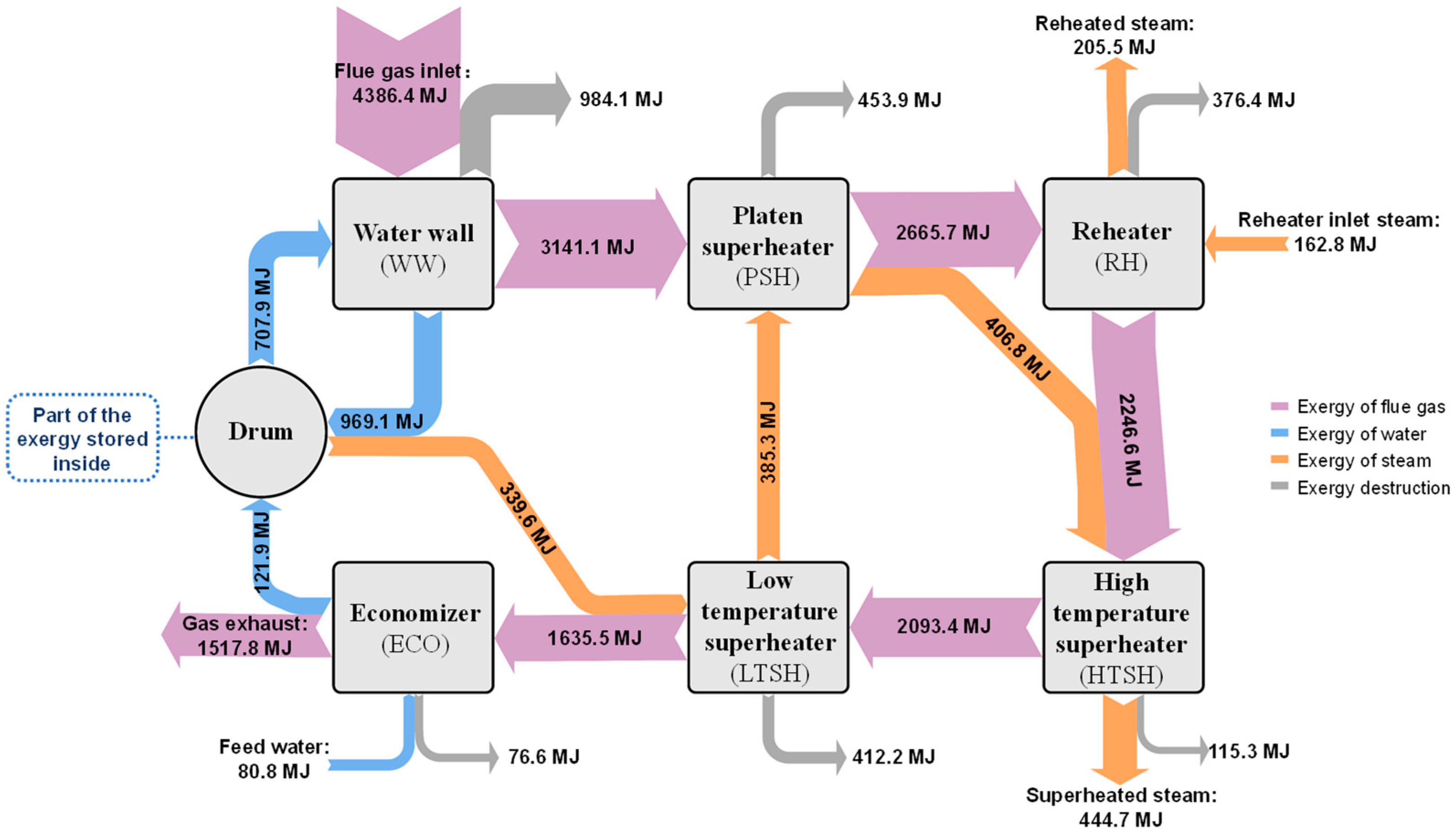
3.1. Steady-State Analysis

The power plant boiler thermal system model is established using Modelica/Dymola 2022 software, and simulation calculations are conducted under turbine-rating load condition. The temperature, pressure, mass flow rate, enthalpy, and entropy of each working fluid flow in the boiler heat exchange network system under steady-state operating conditions are obtained, as shown in Table 1.
The exergy flow Sankey diagram of the heat surfaces in a power plant boiler is shown in Figure 3. The drum component serves as a phase separator and accumulator for the working fluid, storing a part of the exergy due to its thermal inertia and the exergy content of the water and steam it contains. The heat exchange networks primarily contain thermal energy, which is of lower quality, and its quality increases with higher temperatures. The boiler system has three input exergy sources. Firstly, the high-temperature flue gas at the furnace outlet serves as the heat source, with a maximum exergy of 4386.4 MJ. The feedwater entering the system from the economizer and the reheated steam input are used as the heated working medium, and the total exergy is 80.8 MJ and 162.8 MJ, respectively. The exergy input of the flue gas gradually diminishes throughout the multi-stage heat transfer process, resulting in a total exergy reduction of 2868.6 MJ, attributable to irreversible heat transfer phenomena. Eventually, following the complete heat exchange process, the residual exergy output of the flue gas amounts to 1517.8 MJ. As the working medium traverses the boiler’s heat exchange networks, the principal output products comprise main steam and reheat steam, possessing values of 444.7 MJ and 205.5 MJ, respectively.
The process of transferring heat from high-temperature working fluids to low-temperature objects can result in decreased energy quality. Heat transfer causes exergy destruction in multi-stage boiler networks due to temperature differences. The proportion of exergy destruction to various components of the boiler heat networks is shown in Figure 3. According to Figure 4, the evaporator unit and superheater unit account for 81.3% of the system’s exergy destruction. The WW is responsible for the highest exergy destruction in the boiler heat exchange networks, accounting for 40.7%. This is mainly because the first heat transfer process between the flue gas and the steam/water system takes place in the WW, and the average heat transfer temperature difference is the largest, with a maximum of 1140 °C. Additionally, as part of the steam/water cycle within the evaporator unit, the working fluid undergoes a phase transition, which significantly contributes to exergy destruction. The exergy destruction within the heat exchange networks progresses along the path of flue gas flow, commencing from the largest to the smallest units, encompassing the evaporator, superheater, reheater, and economizer units. Throughout the sequential heat exchange process, the temperature differential between the flue gas and steam/water system gradually diminishes, resulting in a decrease in exergy destruction.

3.2. Dynamic Exergy Assessment
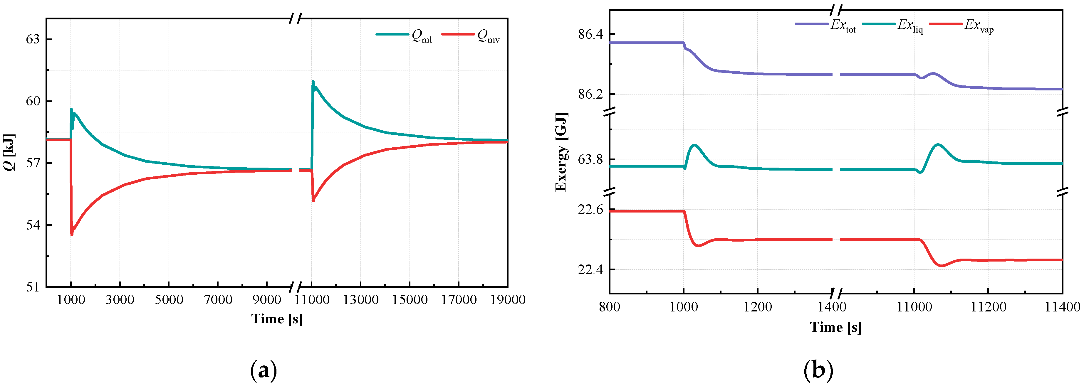
To investigate the dynamic performance of the boiler heat exchange system, dynamic simulations were conducted using Modelica/Dymola software. The simulations were run for a total duration of 30,000 s with a time step of 2 s. The first disturbance introduced was a step decrease in the flue gas inlet flow rate by 20 kg/s (a reduction of 5%) at the 1000 s mark, after the working fluid flow rates had reached steady-state conditions. The second disturbance involved reducing the feedwater temperature by 4.9 °C (a decrease of 1.8%) at the 11,000 s mark.

3.2.1. Drum

Figure 5 illustrates the response of heat transfer quantity and exergy between the wall and working fluid in the drum. The wall surface’s significant heat capacity and inertia contribute to a gradual temperature decrease and prolonged adjustment time. The dynamic process of heat transfer quantity under the two disturbance conditions persisted for over 5000 s. Consequently, there is also an observable phenomenon of delayed heat transfer between the wall and liquid or steam, as illustrated in Figure 5a.
The variation in exergy of working medium is influenced by temperature, mass flow rate, and heat transfer quantity. As depicted in Figure 5b, the dynamic change trend of the working fluid in the drum aligns with the temperature response after two disturbances. However, the behavior of water flow is more significantly impacted by the mass flow rate, evident in the dynamic fluctuations of liquid volume due to water level adjustments following the disturbances. Regarding the total mass of the working fluid in the drum, the decrease in working fluid temperature and evaporation resulting from reduced heat transfer due to the disturbances lead to a simultaneous decrease in the total mass of the working fluid in the drum.

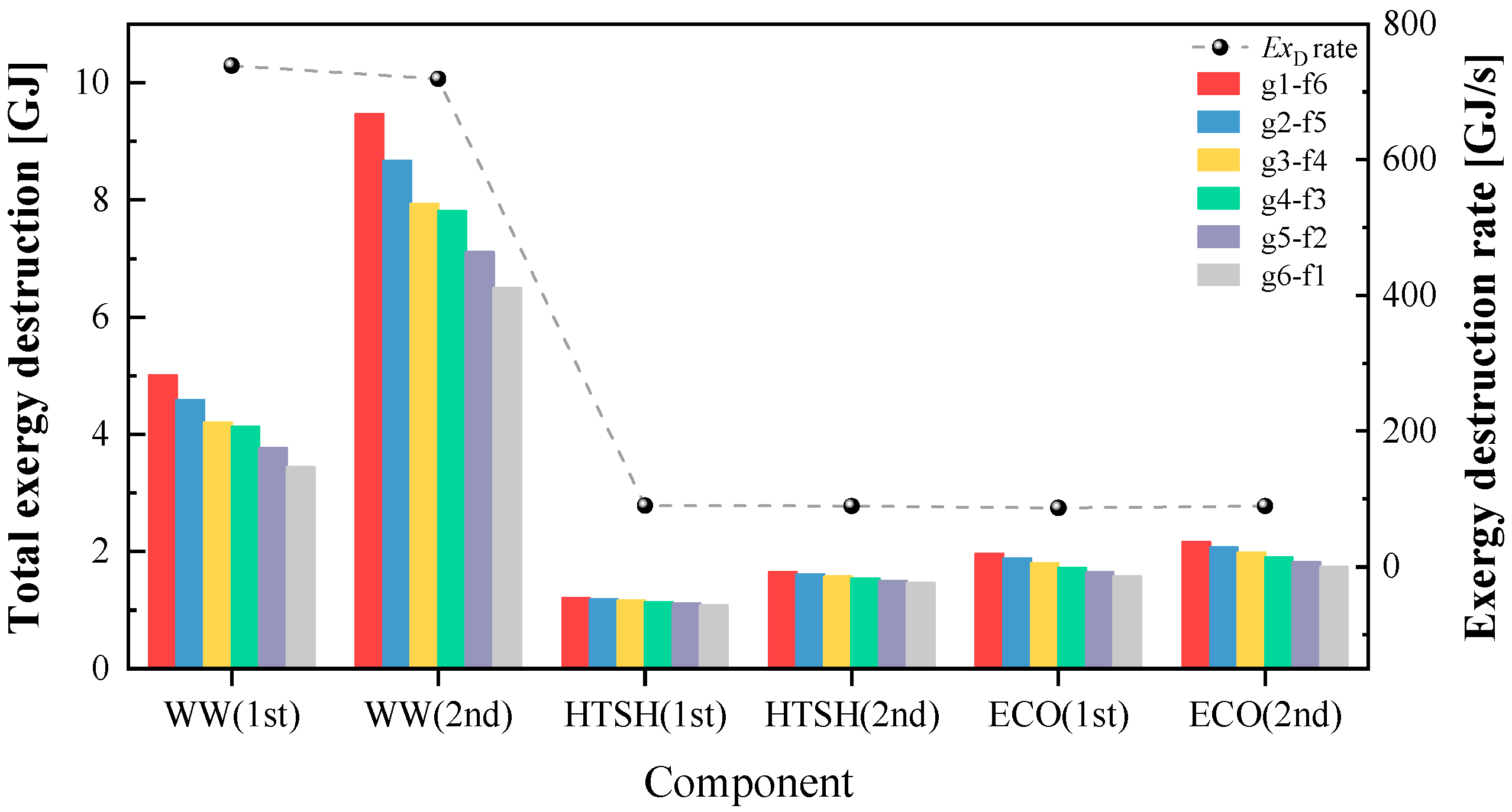
3.2.2. Heating Surfaces

The exergy destruction rate and total exergy destruction for each component node in the dynamic process are displayed in Figure 6. The total exergy destruction for the three key heat exchange components decreases from a high-temperature flue gas inlet to the outlet. Notably, the heat transfer process between the flue gas inlet and the fluid outlet node (g1-w6) in the WW demonstrates the highest total dynamic exergy destruction of 9.5 GJ. This peak exergy destruction in the WW indicates its significant role in energy conversion and irreversibility within the boiler system, primarily due to the large temperature difference and phase change occurring in this component. Despite the WW components having the shortest dynamic process, the exergy destruction per unit time surpasses that of other components by 7.9–8.5 times, reaching up to 738.8 GJ/s. Consequently, the total exergy destruction under the two disturbance conditions in WW is significantly greater. As for the HTSH and the ECO, the exergy destruction rate per unit time under the two disturbances is comparable. However, due to differences in dynamic process duration, the total exergy destruction of the heat exchange nodes under the two disturbances in the ECO is slightly higher than that of the HTSH.

4. Conclusions

This study evaluates the dynamic thermodynamic characteristics of boiler heating surfaces to inform strategies for enhancing operational efficiency and performance in drum-type boilers. By quantifying exergy destruction and thermal inertia, the analysis provides actionable insights for optimizing boiler systems. Specifically, the main conclusions are as follows:
(1)
During steady-state operation, the evaporator and superheater unit contribute to 81.3% of the total exergy destruction in the boiler heat networks. Notably, the water wall, platen superheater, and low-temperature superheater exhibit the highest proportions of irreversible loss within the boiler heat exchange networks.
(2)
The thermal inertia induced by the drum wall results in a significant delay in energy changes, with a dynamic period of up to 5000 s. Consequently, the phenomenon leads to delayed exergy fluctuations of liquid and steam in the drum.
(3)
The dynamic exergy analysis highlights that the water wall demonstrates the highest total dynamic exergy destruction of 9.5 GJ. Despite the water wall components having the shortest dynamic process, the exergy destruction per unit time surpasses that of other components by 7.9–8.5 times, reaching up to 738.8 GJ/s.
These findings guide the optimization of drum-type boilers for improved energy efficiency and operational flexibility, particularly in coal-fired power plants transitioning to peak-shaving roles. The exergy-based approach can be extended to monitor real-time performance and inform maintenance schedules, ensuring sustained efficiency under varying operational conditions. While this study focuses on a coal-fired drum-type boiler, the exergy analysis framework and optimization strategies may be adapted to other boiler types, such as biomass or cogeneration systems, where comparable exergy destruction and thermal inertia phenomena are observed.

Author Contributions

Conceptualization, X.W., C.W. and L.S.; methodology, X.W., J.Z. and L.S.; software, C.W., H.W. and C.D.; validation, X.W., H.W. and C.D.; formal analysis, C.W., C.D. and L.S.; investigation, J.Z. and H.W.; resources, X.W. and L.S.; data curation, C.W., C.D. and H.W.; writing—original draft preparation, X.W. and J.Z.; writing—review and editing, C.W., H.W. and L.S.; visualization, C.D.; supervision, L.S.; funding acquisition, X.W. and L.S. All authors have read and agreed to the published version of the manuscript.

Funding

This research was funded by the Grant of Guoneng Nanjing Electric Power Test & Re-search Limited, grant number DY2024Y02.

Data Availability Statement

The datasets used in this article are confidential.

Conflicts of Interest

The authors declare that the research was conducted in the absence of any commercial or financial relationships that could be construed as a potential conflict of interest.

Nomenclature

The following nomenclature are used in this manuscript:
Aiheat transfer area, m2
cvg,ispecific heat capacity of flue gas volume segment i, kJ/(kg·K)
Eenergy, kJ
Exexergy, kJ
exspecific exergy, kJ/kg
Henthalpy, kJ
hspecific enthalpy, kJ/kg
kiheat transfer coefficient, W/(m2·K)
Lm,ilength of the metal segment i, m
Mmass, kg
mmass flow rates, kg/s
Qm,ienergy of heat transfer, W
rradius, m
Sentropy, kJ/K
Titemperature of segment i, K
Φiheat flux, W
ρcmdensity of the metal, kg/m3

Abbreviations

The following abbreviations are used in this manuscript:
WWWater wall
PSHPlaten superheater
HTSHHigh-temperature superheater
LTSHLow-temperature superheater
RHReheater
ECOEconomizer

References

  1. Energy Institute Statistical Review of World Energy 2024. Available online: https://www.energyinst.org/statistical-review (accessed on 26 December 2021).
  2. Guo, M.; Hao, Y.; Nižetić, S.; Lee, K.Y.; Sun, L. Modelica-Based Heating Surface Modelling and Dynamic Exergy Analysis of 300 MW Power Plant Boiler. Energy Convers. Manag. 2024, 312, 118557. [Google Scholar] [CrossRef]
  3. Wang, Z.; Liu, M.; Yan, J. Flexibility and Efficiency Co-Enhancement of Thermal Power Plant by Control Strategy Improvement Considering Time Varying and Detailed Boiler Heat Storage Characteristics. Energy 2021, 232, 121048. [Google Scholar] [CrossRef]
  4. Wang, Y.; Lou, S.; Wu, Y.; Wang, S. Flexible Operation of Retrofitted Coal-Fired Power Plants to Reduce Wind Curtailment Considering Thermal Energy Storage. IEEE Trans. Power Syst. 2020, 35, 1178–1187. [Google Scholar] [CrossRef]
  5. Guo, M.; Hao, Y.; Lu, Y.; Sun, L. Long-Short Term Memory Modeling and Performance Analysis of Extended-State Kalman Filter-Based Energy-Saving Model Predictive Control for Supercritical Unit. Appl. Therm. Eng. 2025, 272, 126202. [Google Scholar] [CrossRef]
  6. Noroozian, A.; Mohammadi, A.; Bidi, M.; Ahmadi, M.H. Energy, Exergy and Economic Analyses of a Novel System to Recover Waste Heat and Water in Steam Power Plants. Energy Convers. Manag. 2017, 144, 351–360. [Google Scholar] [CrossRef]
  7. Ouyang, T.; Xie, S.; Pan, M.; Qin, P. Peak-Shaving Scheme for Coal-Fired Power Plant Integrating Flexible Carbon Capture and Wastewater Treatment. Energy Convers. Manag. 2022, 256, 115377. [Google Scholar] [CrossRef]
  8. Chandrasekharan, S.; Panda, R.C.; Swaminathan, B.N.; Panda, A. Operational Control of an Integrated Drum Boiler of a Coal Fired Thermal Power Plant. Energy 2018, 159, 977–987. [Google Scholar] [CrossRef]
  9. Chen, C.; Zhou, Z.; Bollas, G.M. Dynamic Modeling, Simulation and Optimization of a Subcritical Steam Power Plant. Part I: Plant Model and Regulatory Control. Energy Convers. Manag. 2017, 145, 324–334. [Google Scholar] [CrossRef]
  10. Stanger, L.; Schirrer, A.; Benedikt, F.; Bartik, A.; Jankovic, S.; Müller, S.; Kozek, M. Dynamic Modeling of Dual Fluidized Bed Steam Gasification for Control Design. Energy 2023, 265, 126378. [Google Scholar] [CrossRef]
  11. Fu, Y.; Wang, L.; Liu, M.; Wang, J.; Yan, J. Performance Analysis of Coal-Fired Power Plants Integrated with Carbon Capture System under Load-Cycling Operation Conditions. Energy 2023, 276, 127532. [Google Scholar] [CrossRef]
  12. Chen, Y.; Guo, M.; Liu, Y.; Wang, D.; Zhuang, Z.; Quan, M. Energy, Exergy, and Economic Analysis of a Centralized Solar and Biogas Hybrid Heating System for Rural Areas. Energy Convers. Manag. 2023, 276, 116591. [Google Scholar] [CrossRef]
  13. Açıkkalp, E.; Caliskan, H.; Altuntas, O.; Hepbasli, A. Novel Combined Extended-Advanced Exergy Analysis Methodology as a New Tool to Assess Thermodynamic Systems. Energy Convers. Manag. 2021, 236, 114019. [Google Scholar] [CrossRef]
  14. Zhang, Q.; Yi, H.; Yu, Z.; Gao, J.; Wang, X.; Lin, H.; Shen, B. Energy-Exergy Analysis and Energy Efficiency Improvement of Coal-Fired Industrial Boilers Based on Thermal Test Data. Appl. Therm. Eng. 2018, 144, 614–627. [Google Scholar] [CrossRef]
  15. Hashemi Beni, M.; Emami, S.; Meghdadi Isfahani, A.H.; Shirneshan, A.; Kalbasi, R. Transient Simulation and Exergy Analysis of a D-Type Steam Boiler with Natural Circulation during Cold Start: A Case Study. Appl. Therm. Eng. 2022, 210, 118367. [Google Scholar] [CrossRef]
  16. Huang, G.; Huang, C.; Liu, H.; Huang, H.; Shang, W.; Wang, W. Exergy Analysis of Off-Design Performance in Solar-Aided Power Generation Systems: Evaluating the Rationality of Using Part-Load Operation Solution of Coal-Fired Plants. Energy 2024, 302, 131749. [Google Scholar] [CrossRef]
  17. Zhang, H.; Hao, R.; Liu, X.; Zhang, N.; Guo, W.; Zhang, Z.; Liu, C.; Liu, Y.; Duan, C.; Qin, J. Thermodynamic Performance Analysis of an Improved Coal-Fired Power Generation System Coupled with Geothermal Energy Based on Organic Rankine Cycle. Renew. Energy 2022, 201, 273–290. [Google Scholar] [CrossRef]
  18. Cheng, X.; Liang, X. Heat Transfer Entropy Resistance for the Analyses of Two-Stream Heat Exchangers and Two-Stream Heat Exchanger Networks. Appl. Therm. Eng. 2013, 59, 87–93. [Google Scholar] [CrossRef]
  19. Guo, M.; Hao, Y.; Lee, K.Y.; Sun, L. Extended-State Kalman Filter-Based Model Predictive Control and Energy-Saving Performance Analysis of a Coal-Fired Power Plant. Energy 2025, 314, 134169. [Google Scholar] [CrossRef]
Figure 1. Schematic diagram of boiler heating surfaces.
Thermo 05 00017 g001
Figure 2. Research framework.
Thermo 05 00017 g002
Figure 3. Exergy flow Sankey diagram of boiler heating surfaces.
Thermo 05 00017 g003
Figure 4. The proportion of exergy destruction of each equipment in boiler heating surfaces. PSH: platen superheater; HTSH: high-temperature superheater; LTSH: low-temperature superheater.
Thermo 05 00017 g004
Figure 5. Heat transfer quantity and exergy in the drum: (a) heat transfer quantity; (b) exergy.
Thermo 05 00017 g005
Figure 6. The total exergy destruction and exergy destruction rate for each heating surfaces.
Thermo 05 00017 g006
Table 1. Thermodynamic properties of each stream in base case condition.
MediumStream LocationT [℃]P [bar] m ˙ [kg/s] h [kJ/kg]s [kJ/kg·K]
Flue gasFurnace inlet1600.0 1.25 400.0 12031.5 8.78
Platen superheater inlet1083.1 1.18 400.0 8794.2 8.35
Platen superheater outlet892.3 1.13 400.0 7545.0 8.15
Reheater outlet 690.5 1.11 400.0 6465.4 8.04
High-temperature superheater outlet623.8 1.05 400.0 6029.3 7.86
Economizer inlet424.4 1.03 400.0 4795.7 7.56
Exhaust gas375.5 1.01 400.0 4469.2 7.45
WaterEconomizer outlet273.6 186.56 258.0 1199.4 2.97
Water wall inlet291.8 186.54 294.7 1407.3 3.34
Water wall outlet351.0 187.99 1278.7 1677.8 3.78
SteamDrum outlet359.3 186.54 1278.7 1919.6 3.91
Platen superheater inlet355.1 176.14 294.7 2449.3 3.84
Platen superheater outlet390.6 175.88 294.7 2795.3 5.56
Low-temperature superheater outlet495.6 175.73 294.7 3191.8 6.13
Reheater inlet541.0 175.29 294.7 3398.5 6.39
Reheater outlet325.0 36.60 146.8 3038.8 6.53
Disclaimer/Publisher’s Note: The statements, opinions and data contained in all publications are solely those of the individual author(s) and contributor(s) and not of MDPI and/or the editor(s). MDPI and/or the editor(s) disclaim responsibility for any injury to people or property resulting from any ideas, methods, instructions or products referred to in the content.

