1. Introduction
For effective heat transfer by conduction, materials with high thermal conductivity, such as copper, are used as heat sinks in consumer electronics. Moreover, good thermal contact between the heat sink and central processing unit (CPU) surfaces is required, across which the heat transfer occurs. The use of expensive thermally conducting materials as heat sinks will not be effective in the absence of good thermal contacts, which can be attained with the use of a thermal interface material (TIM) [
1]. The increasing power consumption of modern CPUs and graphics processing units (GPUs) used in modern computers demand significantly improved TIMs to manage their power dissipation. As the materials to be interfaced are good thermal conductors such as copper, the effectiveness of a TIM is enhanced by high thermal conductivity. In addition, the low thickness of the interface material, as well as low thermal contact resistance between the interface material and each mating surface, are also required [
2]. Since the mating surfaces are not perfectly smooth, the interface material must be able to flow or deform so as to conform to the topography of the mating surfaces.
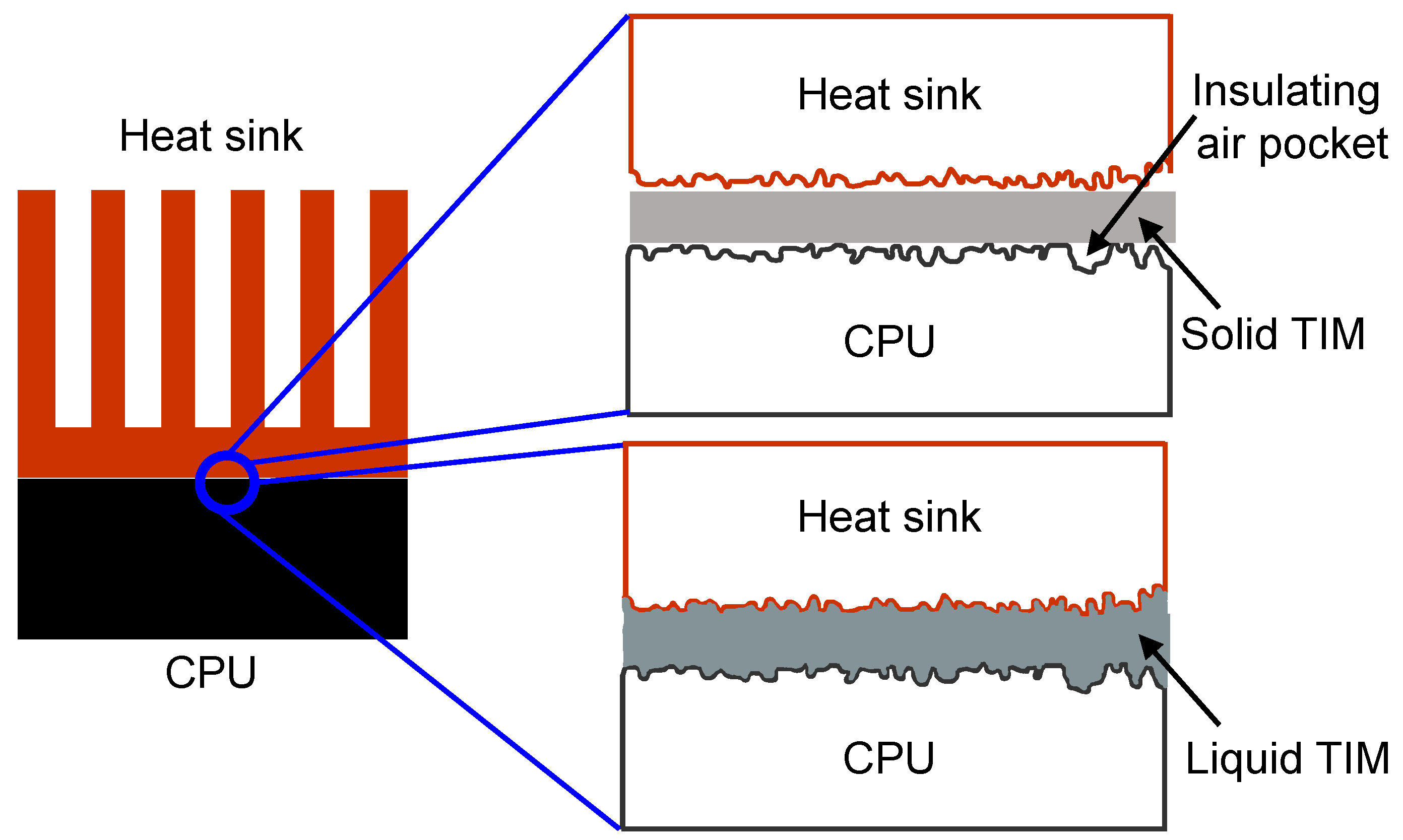
Figure 1 illustrates the difference between the use of a solid TIM such as elastomeric pads and liquid TIM such as thermal greases and pastes in between the CPU and the heat sink. The solid TIM will lead to the formation of small insulating air pockets that will obstruct the heat conduction between CPU and heat sink. On the other hand, a liquid TIM will conform to the surface undulations of the mating surfaces efficiently such that there are no air pockets formed between the CPU and the heat sink, hence, leading to much more effective conduction of heat as shown in
Figure 1.
The characteristics of an ideal TIM are high thermal conductivity, minimal thickness, non-toxic, manufacturer friendly, and can be easily deformed by small contact pressure to conform to the surface undulations in both the mating surfaces [
1]. Therefore, it is evident that TIMs that can exist as the liquid phase at the service temperature (20–100 °C) for electronic applications are highly desirable for attaining higher heat conduction with maximum thermal contact between the mating surfaces. Besides, liquids that possess high thermal conductivity will be more suitable, and hence, liquid metals or metallic alloys can be potentially applied as TIMs. It is well known that only two metals can exist as liquid close to room temperature, namely, mercury (Hg) and gallium (Ga). Since Hg is known to be toxic, Ga is the obvious choice as its melting point is close to room temperature (~30 °C). The addition of an alloying element that has high solubility with Ga allows the liquid phase to be stable for an extended composition range. Indium (In) belongs to the same group as Ga with the same valency, similar crystal structure (In: tetragonal and Ga: orthorhombic), lower melting point (~157 °C) in comparison with other elements and comparable thermal conductivity. Hence, liquid Ga-In alloys can be considered as a candidate material for TIM in consumer electronics, and knowledge of its thermal conductivity is imperative.
At present, thermal conductivity (
κ) of metallic alloys, especially the solid phases, are calculated from the specific heat capacity (
Cp), thermal diffusivity (
α), and density (
ρ) using the following equation [
3,
4]
The thermal diffusivity as a function of temperature and density at room temperature are measured using the laser flash method and Archimedes principle, respectively. The specific heat capacity is determined either using the Neumann-Kopp rule [
3] or from equilibrium calculations with the thermodynamic database developed using the CALPHAD (calculation of phase diagrams) method as input [
4]. The error associated with the measurement of thermal diffusivity using the laser-flash method is nearly ±3% [
3,
4] and the uncertainty in the density measurements using the Archimedes principle is ±5%. In addition, the reliability of the calculated specific heat capacities were assessed to be less than ±5% [
3,
4]. Hence, due to the propagation of errors during the multiplication of these quantities, the total error in the thermal conductivity values calculated using Equation (1) is ~±13%. Moreover, this method has not been demonstrated to be successful for materials in the liquid state.
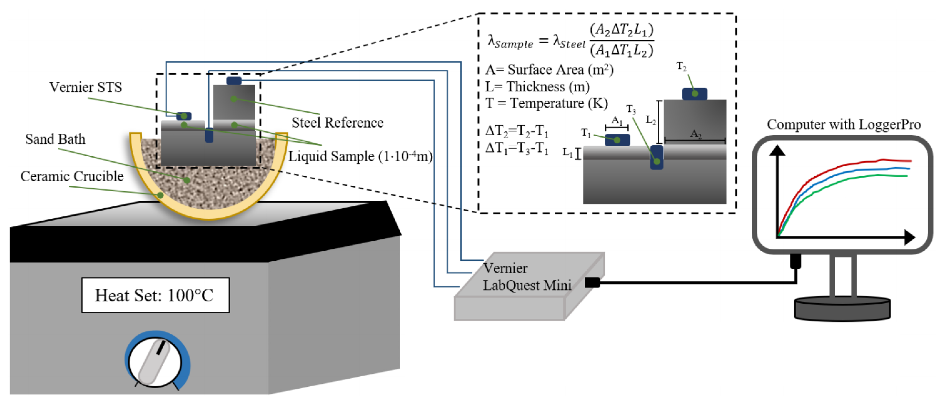
In order to circumvent this shortcoming, a modified comparative cut bar technique is used for the measurement of thermal conductivity of the Ga-In alloys in liquid and semi-liquid state, in this work. In the comparative cut bar technique, two materials are involved, namely the sample and the standard that are placed in series between the heat source and the heat sink [
5], as shown in
Figure 2a. The thermal conductivity of the standard material is known. This setup is heated by a heat source with known steady-state power input, and the change in temperature (ΔT) is measured using the temperature sensors that are placed in the sample and the standard across a given length (L) after a steady-state temperature distribution is reached. In general, either thermocouples or thermistors are used as the temperature sensors, and the error associated with the measurement of ΔT will be less than ±1%. Since the amount of heat flow through the standard equals to the heat flow through the sample, the thermal conductivity of the sample is given by [
5],
where the subscripts 1 and 2 denote the sample and the standard, respectively, and A is the surface area. Since the uncertainty arises from the measurement of temperature change, surface area, and thickness with 0.5%, 0.1%, and 0.1% uncertainty, respectively, this method is accurate for the measurement of thermal conductivity. The changes to the original setup were undertaken in this work such that the process will be transient and capable of measuring the conductivity of liquid and semi-liquid alloys. The setup was modified as shown in
Figure 2b, where the standard is in contact with half of the sample. It is assumed that the temperature at the sample/standard interface is equal to the temperature at the exposed surface of the sample. Therefore, only three temperature sensors will be required for the measurement of thermal conductivity using the modified method.
The CALPHAD method [
6,
7] is a useful tool to establish databases for thermophysical properties [
8,
9,
10,
11]. It involves a computer-assisted modeling procedure with experimental data as input to develop a set of self-consistent parameters for the description of the thermophysical property. One of the major advantages of this technique is though, limited experimental data from a certain composition and temperature range are used as input for the database development, the properties of alloys in other composition and temperature ranges can be estimated. This cuts down the experimental efforts and costs drastically. In the present study, the thermal conductivities of Ga-In alloys in liquid and semi-liquid phase regions were measured using the modified comparative cut bar technique. With the available experimental data from literature and measurements from present work as input, the thermal conductivities of the Ga-In system, including the pure elements, solution phases, and two-phase regions, were evaluated using the CALPHAD method.
2. Materials and Methods
The Ga-In phase diagram calculated using the Gibbs energy descriptions developed by Anderson et al. [
12] is shown in
Figure 3. Five In
xGa
1−x alloys (x = 0, 0.1, 0.214, 0.3 and 0.9) were considered in this work from different regions namely, α, eutectic (
xIn = 0.214), liquid, and liquid + β regions. α and β denote the Ga and In phases, respectively. There is a limited dissolution of Ga into In, whereas, a negligible dissolution of In into Ga, as shown in
Figure 3. The thermal conductivities of these alloys were measured at four different temperatures namely, 40 °C, 60 °C, 80 °C, and 100 °C. These temperatures were chosen since they describe the range in which standard CPUs can operate, as there is a ubiquitous safety feature which shuts the computer down after the CPU exceeds 100 °C, and they often “idle” near 30–40 °C. The thermal conductivity of the β phase could not be measured since In is solid in the temperature range of interest, and the setup was mainly designed for measuring the thermal conductivity of the liquid/semi-liquid phase. Vials of Ga (purity: 99.99%, Fisher Scientific, Waltham, MA, USA) and In powder (purity: 99.99%, Fisher Scientific) were chosen as the raw materials. These alloys were prepared by simple mechanical mixing with a steel spatula, as the Ga and In readily dissolve each other at room temperature. The potential for Ni and Fe contamination was considered to be negligible, as demonstrated by Prokhorenko et al. [
13] that the dissolution of these metals into Ga was in the order of 10
−2 wt.% after sustained heating at higher temperatures and time periods than those used in this work. Hence, either low alloy steel or pure iron needs to be chosen as the standard as elements other than Fe and Ni could add systematic error to the measurements by dissolving into the Ga-In alloy.
As shown in
Figure 4, the temperature of the sample, standard, and heat source were recorded using surface temperature sensors (STS, supplied by Vernier, Beaverton, OR, USA) and recorded using the LoggerPro software through a Vernier LabQuest Mini. One sensor was embedded into the surface of the heat source via a shallow drilled hole, and the sensor monitoring the standard was affixed using a small amount of cyanoacrylate glue. The STS that measures the surface temperature of the sample directly was lightly ground to provide a known surface area for the area of contact. After one of the sensors was ground, it was imaged using an optical microscope with a known scale, and the surface area was calculated from this image using ImageJ. Subsequently, the sensors (and the surfaces they were affixed in/on) were calibrated using LoggerPro’s calibration function against an ice bath, a 50 °C sand bath kept in a laboratory oven (Fisherbrand Isotemp, Fisher Scientific), and boiling water. In each instance, once the voltage readings from all of the sensors remained unchanged for more than 15 min, they were considered to be at thermal equilibrium with the system, and the temperature of the sensors were set equal to the target temperatures mentioned above. The hotplate was set to the desired final temperature, and the system was given an hour to equilibrate and allow the temperatures to stabilize, with each STS recording the temperature every 2 s. After the completion of each trial, a logistic fit was applied to each curve, in order to eliminate the moment-to-moment relative temperature fluctuations and their effect on the calculation of the final thermal conductivity.
4. Results and Discussion
Currently, the TIMs that are used in consumer electronics are thermally conductive elastomers, thermal grease, and phase change materials (PCMs). Thermally conductive elastomers, which are a type of solid TIM, require high contact pressures in order to fill the gaps in between the mating surfaces for effective conduction, and their thermal conductivities are very low (~1.2 Wm
−1K
−1) [
1]. Subsequently, an improved TIM called thermal grease was introduced, which was composed of a thermally conductive filler dispersed in silicone or hydrocarbon oil to form a paste [
18]. These materials exhibit high thermal performance at low contact pressures (~12 psi) [
19] and can fill the interstices of the mating surfaces efficiently. The reported thermal conductivities of the thermal greases currently available in the commercial market are between 3 and 7.5 Wm
−1K
−1 [
1]. However, thermal greases are not manufacturer friendly as they are messy and difficult to apply, and the grease degradation rate is a strong function of operating temperature and number of thermal cycles [
20].
PCMs are made of a mixture of suspended particles of high thermal conductivity, such as fine particles of metal oxide and base material. The name “phase change material” is a misnomer since it is not a phase but a change in viscosity occurs in this material [
21]. The base material can be a natural material such as fully refined paraffin, polymer, co-polymer, or a combination of all [
22]. The base material is solid at room temperature and behaves like grease after reaching the phase change temperature (50–90 °C). Commercially available PCMs are in the form of a compound or composite of specified thickness, and their thermal conductivity ranges between 0.7 and 20 Wm
−1K
−1 [
1]. However, moderate contact pressure (10–50 psi) is required to bring contact between the mating surfaces, and the phase change properties limit the choice of base material and filler combinations [
20].
The thermal conductivity values measured using the modified comparative cut bar technique at various compositions corresponding to different phase regions of the Ga-In system at various temperatures using Equation (2) are summarized in
Table 1. It is clearly evident that the thermal conductivity of pure Ga in the liquid state, as well as the liquid and semi-liquid Ga-In alloys, are much higher than the majority of the currently available commercial TIMs. The primary criterion (i.e., the high thermal conductivity of Ga-In alloys and pure Ga to serve as a TIM) has been satisfied. Both In and Ga are non-toxic, and simple mechanical mixing at room temperature is sufficient for producing these alloys due to their high solubility in the liquid state and are thus extremely manufacturer friendly. Moreover, the liquid and semi-liquid states of TIMs require lower contact pressures to fill the air pockets between the mating surfaces than other solutions and are incapable of drying out or degrading such as thermal greases. This proves that Ga-In alloys in the liquid and semi-liquid states, satisfy all of the criterion required for an ideal TIM in consumer electronic applications.
From this study, it has also been proved that the modified comparative cut bar technique can be applied successfully for the measurement of thermal conductivities of liquid and semi-liquid metallic alloys. The original comparative cut bar technique can be used for measurement of the thermal conductivity of solid phases in place of the currently used technique that involves the measurement of thermal diffusivity and density as well as estimation of specific heat capacity. This is due to the fact that the error associated with the former technique is very low (~±1%) which arises only from the temperature drop measurement, in comparison with the high error (~±13%) that arises due to the multiplication of the individual quantities (Equation (1)) in the latter. At present, this measurement technique has been applied from room temperature to a maximum temperature of 100 °C for low melting alloys such as the Ga-In system. However, with the use of improved temperature sensors that can detect higher temperatures, the modified comparative cut bar technique can possibly be employed for measuring the thermal conductivity of the liquid phase in commercial multicomponent alloys such as steels and Ni-base superalloys. Moreover, it can be observed in
Figure 3 and
Table 1 that the data points for certain temperatures and compositions are missing. These measurements failed probably due to the dissolution of Fe from the steel block that increased the thermal conductivity considerably such that these values become outliers from the trend followed. Thus, it can be understood that the choice of the standard material is crucial, and it should be chosen such that it does not contaminate and alter the thermal conductivity values of the sample material.
The PARROT [
23] module of Thermo-Calc software [
24] was used for optimizing the thermal conductivity model parameters. The thermodynamic equilibrium information, such as solid solubility and mole fraction of phases, were simultaneously extracted by using the thermodynamic database for the Ga-In system [
12] during the optimization of thermal conductivity. Initially, the thermal conductivities of the pure elements in liquid and solid states were optimized. The parameters A, B, and C in Equation (3) were optimized simultaneously for each phase with their corresponding experimental data used as input. All of the experimental data were used for the optimization of the parameters with equal weight for pure In and Ga in both liquid and solid states. Once the parameters of the pure elements were fixed, the thermal conductivity parameters for the liquid phase in the Ga-In system were assessed to obtain the Redlich-Kister interaction parameters with the experimental data measured in this work as input. As the description for the individual phases was established, the interface scattering parameters for the L + β two-phase region were optimized to fit the measured thermal conductivities of the alloys belonging to that phase region from the present work. The thermal conductivity parameters for the individual phases and the two-phase region of the Ga-In system assessed in this work are listed in
Table 2.
The calculated thermal conductivities for pure In and Ga in liquid and solid states are shown in
Figure 5 and
Figure 6 and compared with the reported experimental data from the literature [Refs]. In the case of liquid Ga (
Figure 5a), the experimental data from literature and present work are compared with the calculated thermal conductivity values. It is evident from these figures that all of the experimental data are in good correlation with the calculated values for both the pure elements in liquid and solid states. The high level of precision in the calculated results for pure elements ensures that the thermal conductivity of the liquid and two-phase region in the Ga-In system can be modeled with better accuracy since CALPHAD is an extrapolative technique. Moreover, the measured thermal conductivity values for liquid Ga from the present work matches well with the experimental data reported in the literature for similar temperatures. This again proves that the modified comparative cut bar technique is suitable for measuring thermal conductivities of liquid metallic alloys.
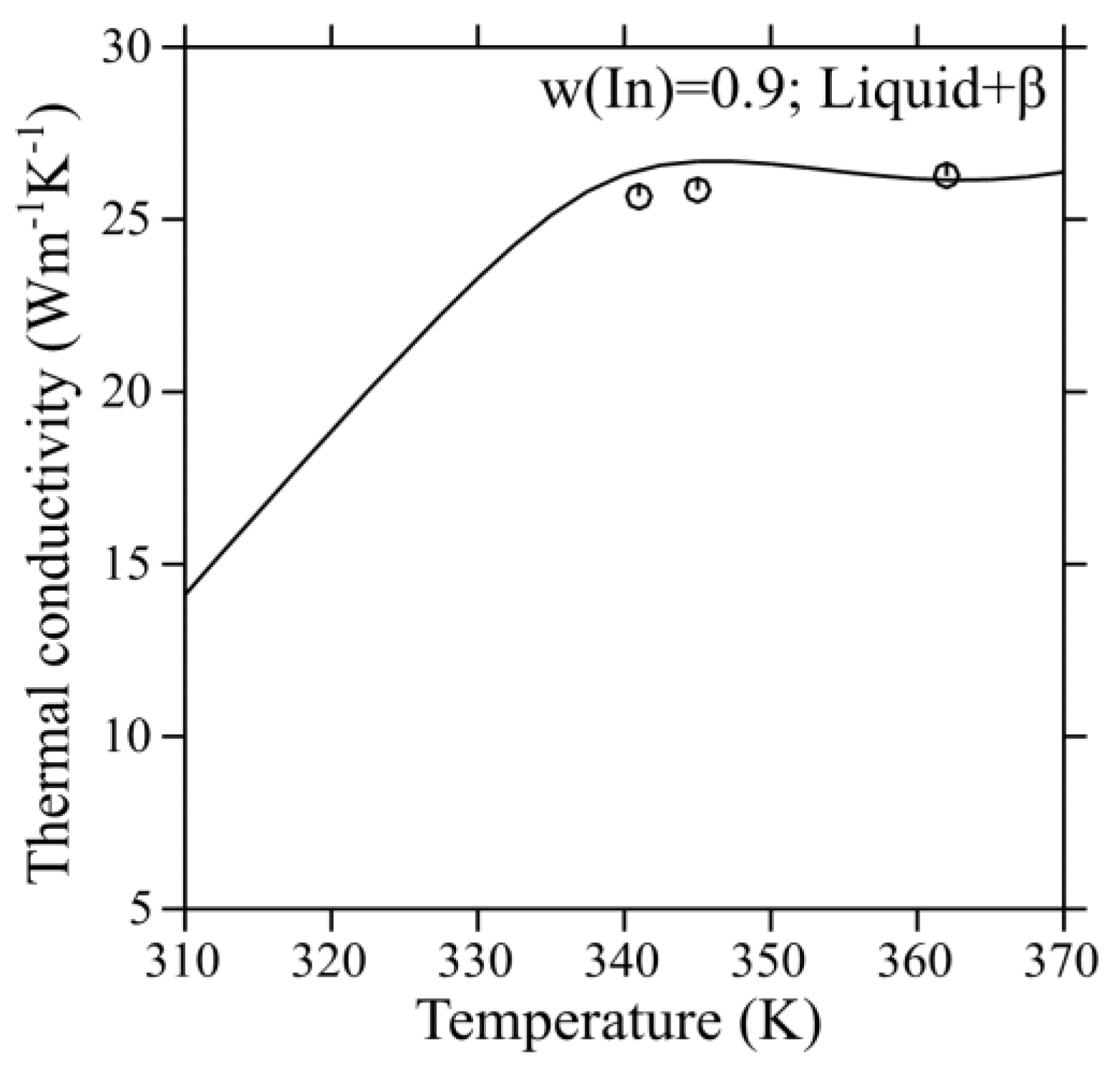
Figure 7 shows the comparison between the calculated and experimental thermal conductivities of the liquid phase in the Ga-In system. It is obvious from these results that most of the experimental data correlates satisfactorily well with the calculated values. Moreover, the thermal conductivity of the liquid Ga-In alloy at w(In) = 0.3 is the highest, while the values for the eutectic alloy and w(In) = 0.1 are similar. The comparison between the experimental thermal conductivities and calculated values in the L + β two-phase region is shown in
Figure 8. It was found that the extrapolation of the thermal conductivity parameters for the liquid and β phases, in combination with the interface scattering parameters, can describe the experimental data reasonably well. It indicates that the thermal conductivities can be altered considerably due to the impediment by interfaces in the two-phase region. Hence, extrapolation from the individual phases alone will not suffice to reproduce the experimental thermal conductivity data satisfactorily using the CALPHAD method in the two-phase region. Besides, the thermal conductivity of the two-phase region is lower than the single-phase liquid due to the presence of interfaces. The interfaces tend to reduce the thermal conductivity due to the scattering of phonons. Nevertheless, it is higher than the highest reported thermal conductivity amongst the currently used TIMs. Thus, a set of self-consistent parameters for the thermal conductivity of pure elements, liquid, and L + β two-phase region of the Ga-In system has been developed successfully using the CALPHAD method with the input data from literature as well as measurements from the present work.
Although the main aim of this work is to look for potential application of Ga-In alloys as TIMs, many investigators have reported thermal properties of liquid metals as TIMs [
25,
26,
27,
28,
29]. It is true that thermal conductivity of the Ga-In alloys is higher compared to the traditional TIMs. However, when it comes to TIM, thermal conductivity is not the only property that has to be considered. Several issues such as wetting and containment are big concerns when work with liquid/semi-liquid metals, which needs to be taken into account. These metals are also electrically conductive and could be corrosive. Thus, there are several areas of concern for successful use of liquid metals as TIMs. Hence, it is worth noting that, this work considers only the thermal conductivities for the potential application of Ga-In alloys to be applied as TIM which is the primary property to be considered and still, several other factors mentioned above needs to be considered, which is a scope for future work. It is also worth noting that instead of using the thermal conductivity in Equations (4) and (6), thermal diffusivities can be considered for the extrapolation, which is also a direction for future work.


