Review

Photocatalytic Applications of Hοllow Fibers and Hollow Fiber Membranes

by
Chrysoula Athanasekou
Institute of Nanoscience and Nanotechnology, National Center for Scientific Research “Demokritos”, Agia Paraskevi, 15341 Athens, Greece
Photochem 2026, 6(1), 12; https://doi.org/10.3390/photochem6010012
Submission received: 30 January 2026 / Revised: 2 March 2026 / Accepted: 9 March 2026 / Published: 16 March 2026
(This article belongs to the Special Issue Feature Review Papers in Photochemistry)

Abstract

Hollow fibers (HFs) have recently gained attention as an advantageous photocatalyst immobilizer for heterogeneous catalysis. Depending on their fabrication method, they can come up, or not, with a porous network within their structure. In this case, they are sometimes referred to as membranes, although they are not applied in liquid flow applications as filters. This work provides a concise overview of all the studies encountered in the literature on photocatalytic hollow fibers (HFs) and hollow fiber membranes (HFMs), clarifying the prevailing confusion about the topic. All publications are categorized with respect to their reported applications in batch liquid, flow, or gas experiments.

1. Introduction

The utilization of photons in chemical reactions has been widely investigated during the past decades. Chemical reactions can speed up using light, in the presence of materials which, when irradiated, have the ability to absorb energy equal to their band gap or wider and create electron-hole pairs (e/h+) within their own molecule, followed by charge separation into electrons (at the conduction band) and holes (at the valence band).
These charge carriers (e/h+) transport to the surface of the catalyst, initiating redox reactions with water or any other molecules in touch with that surface, most likely due to adsorption. This way, water molecules can split, producing H2, the “fuel of the future”, degrade organic pollutants’ molecules, or facilitate new chemistry. More specifically, the excited conduction band electrons react with electron acceptors, such as oxygen (O2), and form superoxide radical anions (O2), which can easily reduce water (H2O) to produce H2O2 and hydroxyl radicals (OH). The valence band holes (h+) possess high oxidation potential and are able to react with water (H2O) or hydroxyl ions (OH) to produce highly reactive hydroxyl radicals (OH). The overall water splitting reaction is H2O → (hv, catαlyst) 2H2 + O2, consisting of the reduction (2H+ + 2e → H2) and the oxidation parts (4h+ + 2H2O → O2 + 4H+).
The most famous of these photocatalysts is TiO2, a semiconductor encountered in three crystalline forms, including the rare orthorhombic brookite, the most thermodynamically stable tetragonal rutile, and also the tetragonal anatase, the most photocatalytically active due to its wider band gap (3.2 eV). Degussa (P25), its commonest commercial form, is a mixture of anatase and rutile in the ratio of 4:1, with its efficiency attributed to a synergetic effect between anatase and rutile in Degussa P25. Its high band gap requires activation by UV irradiation, which represents only 4% of the total solar irradiation [1]; therefore, a lot of studies try to transfer its band gap to the visible light area [2,3].
Towards phasing the crucial drawback of heterogeneous catalysis, which is the final separation of the catalyst powder from the aqueous reaction medium, its immobilization on easy-to-collect media has been attempted [4,5]. Leading choices among these immobilizers are hollow fibers (HFs) and hollow fiber membranes (HFMs).
HFs can be produced by the template, the electrospinning or the conventional spinning technique, while only the latter can fabricate HFMs. The template method is a common way of generating hollow structures, with the templates forming the inside layer, while precursors are coated onto them. Thin, natural fibers, such as cellulose cotton fibers, frequently form such templates, which are covered with polymers/catalysts, most likely through immersion, and the hollow structure occurs, subsequently, by removing the core part. The electrospinning technique produces ultra-fine fabrics of viscous solutions or melts, which are usually loaded in a syringe. The syringe nozzle’s tip (anode) is placed against a metal cathode (collector), an electrical potential is applied, and, therefore, fibers are electrospun.
Nevertheless, the majority of the HFs and all of the HFMs are fabricated by the extrusion of polymer/photocatalyst blends through spinnerets, followed by coagulation of the spun fibers in polymer non-solvent baths. The most commonly used polymers for these extrusions are polyvinylidene fluoride (PVDF), Polysulfone (PSF), Polyethersulfone (PES), and polyethyleneimine (PEI). The spinneret apparatus can be used in a dry, wet, or dry/wet spinning mode, depending on the way the polymer blend precipitates. In dry spinning, the solvent evaporates with hot air, whereas in wet spinning, the polymer precipitates in a liquid bath, and the hybrid dry–wet extrudes polymer into a brief air gap before entering the coagulation (non-solvent) bath, allowing for better control of the fiber properties and faster speeds. The hollowness of their body is achieved by co-extruding the polymer solution and a bore fluid (bad solvent for the used polymer, usually water) through special concentric orifice spinnerets.
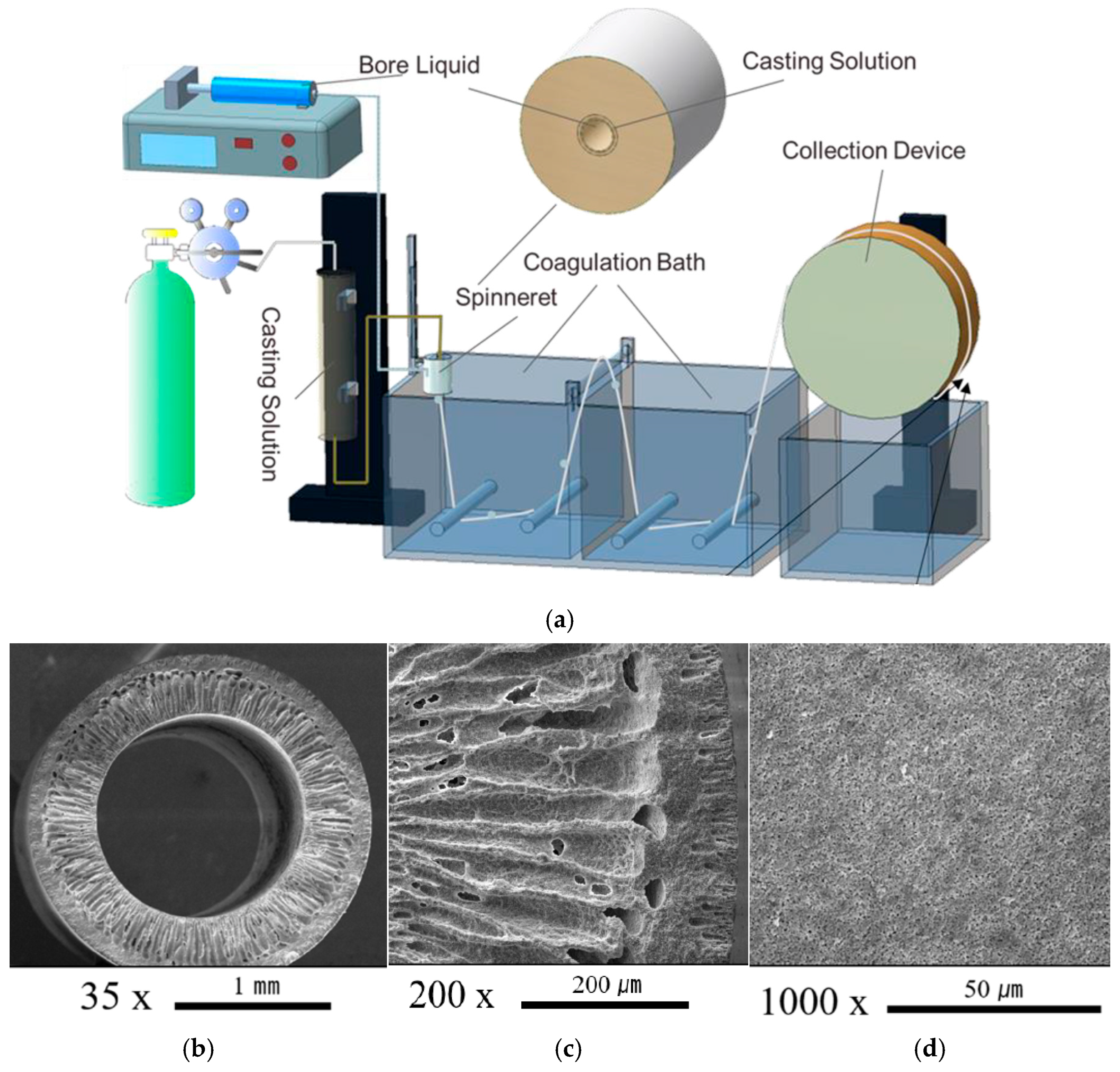
The identifying element that distinguishes a HF from a HFM is the porous structure of the latter that enables it with the separating/filtrating ability. This special structural characteristic is being given to the newly produced hollow fibers through the “phase inversion” in a non-solvent bath. The spun fiber is immersed in a bad solvent (H2O) coagulation bath, and the occurring phase inversion as the “bad polymer solvent” substitutes the “good polymer solvent” and forms a porous network structure within the body of the HF, reforming it into a HFM, creating membranes with controlled pore structure for filtration/separation uses. Figure 1a shows the spinning procedure with the dope solution and the bore liquid, while Figure 1b–d host SEM images of HFMs, with their porous structure being clearly pronounced.
Given the fact that polymers can also be affected/degraded by photocatalysis, a sintering/calcination procedure usually follows the extrusion/phase inversion part of the fabrication to remove the polymer constitutuents and turn the fibers into ceramic ones, therefore suitable for photocatalysis.
In cases where the photocatalyst may not be suspended in the initial polymer extrusion mixture, it may be coated on top of the HF/HFMs afterwards using spray, dip-coating, or chemical bonding methods. Detailed overview of their synthetic routes, as well as their structural and morphological characteristics, is out of the scope of the present review.
An HF’s configuration offers advantages like a large surface area providing abundant active sites for interface reactions and a hollow space creating benefits for light harvesting and multiple reflecting and scattering effects. Additionally, its multi-structure produces a conducive heterojunction, accelerating the directed movement of the built-in electric field and, therefore, the demanded separation of photoexcited charges. Lastly, its large length-diameter ratio in combination with the light weight makes the fibrous photocatalyst easy to recycle. Often being confused with membranes, a HF is exclusively a photocatalyst immobilizer applied in batch conditions of heterogeneous catalytic reactions. Although it may possess a porous structure, it cannot be called a “membrane” unless it is used as one in a filtering process. On the other hand, a HFM is a filter being used exclusively under flow conditions. Like all membranes, it is semi-permeable to some of the ingredients of a mixture and acts as a barrier for the rest. In the case of water solutions, it is characterized by the permeability, the water recovery, and the pollutant rejection value, while in the case of gas mixture separation, the permeability and the selectivity value characterize it.
The membrane water permeability (flux) is commonly measured in L/m2h or L/m2hbar from the equation:
F = V A × Δ t ,
where V is the volume (L) of water permeated during the experiment, A is the effective area (m2) of the membrane, and Δt is the filtration time (h).
The pollutant rejection R (%) is calculated as
R % = C f C p C f × 100 ,
where Cf and Cp are the feed and permeate concentrations.
The water recovery efficiency Y%, is calculated as
Y % = F p F f × 100 ,
where Ff, Fp are the volumetric flow rates of the feed and the permeate, and the energy consumption (kWh/100 m3) is calculated in terms of the pump power over the time needed to drive 100 m3 of water to the membrane module as
E k W h = 100 × P × ρ w S × 36 ,
where P (bar) is the trans-membrane pressure, ρw (g/cm3) is the density of the fluid, and S is the pump efficiency (usually 0.8) [4].
Although the HFMs preparation is more difficult than flat membranes, it is acknowledged that HF modules ensure space savings (higher surface to volume ratio), higher productivity, and ease of maintenance, as they can be backflushed.
Like all catalytic membranes, photocatalytic HFMs exhibit a double action, as they compromise reaction and filtration/separation simultaneously, enabling both processes to occur in a single step. This integration can enhance efficiency and reduce equipment footprint through lowering energy consumption demand, compared to conventional systems, where reaction and separation are carried out in separate units.
Lately, some qualitative reviews have been introduced about photocatalytic membranes in general [8,9,10,11]. The scope of this study is to present exclusively the light-utilizing applications of HFs and HFMs encountered in the literature, categorize them, point out any gaps encountered, and propose directions in this field of research. To the best of the author’s knowledge, this is a comprehensive review of the topic.

2. Liquid Phase Batch Photocatalytic Applications

As mentioned above, most research groups evaluate their HFs in typical batch heterogeneous catalytic experiments against model pollutants and toxic compounds as follows:

2.1. Methylene Blue (MB)

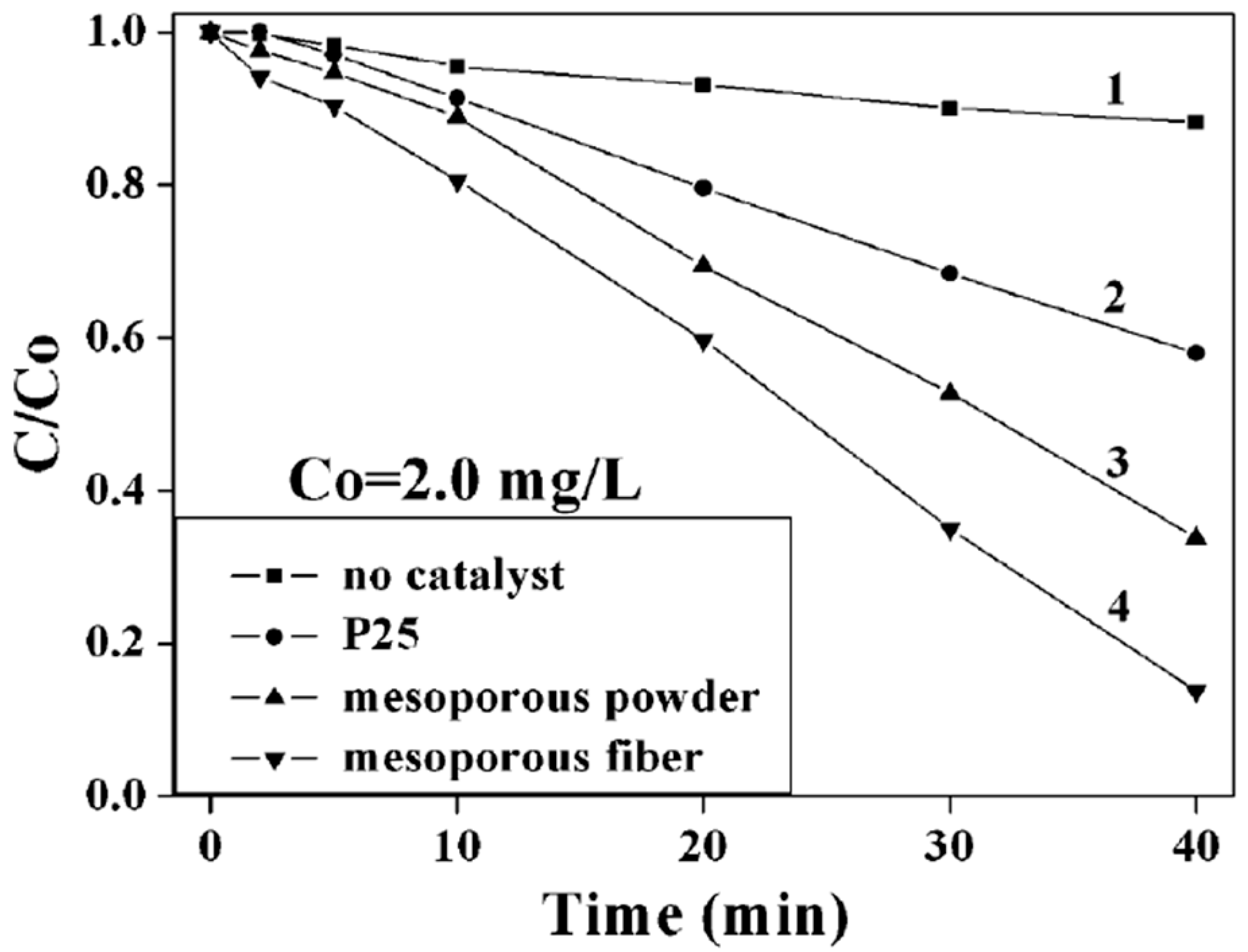
The majority of the HFs have been evaluated by photo-oxidation of MB and compared to the commercial TiO2 P25. Zhan et al. [12] added 1.0 mg of electrospinning-derived core–shell TiO2 HFs (~30 cm, diameter of 0.1–4 μm, wall thicknesses 60–500 nm) to 100 mL of a 2 mg/L MB solution, irradiated by a 125 W mercury lamp (λ = 320–400 nm, λmax = 365 nm) under stirring, and the MB absorption peak at 664 nm is reported to almost disappear after 40 min irradiation, a catalytic behavior better than that of mesoporous TiO2 (Figure 2).
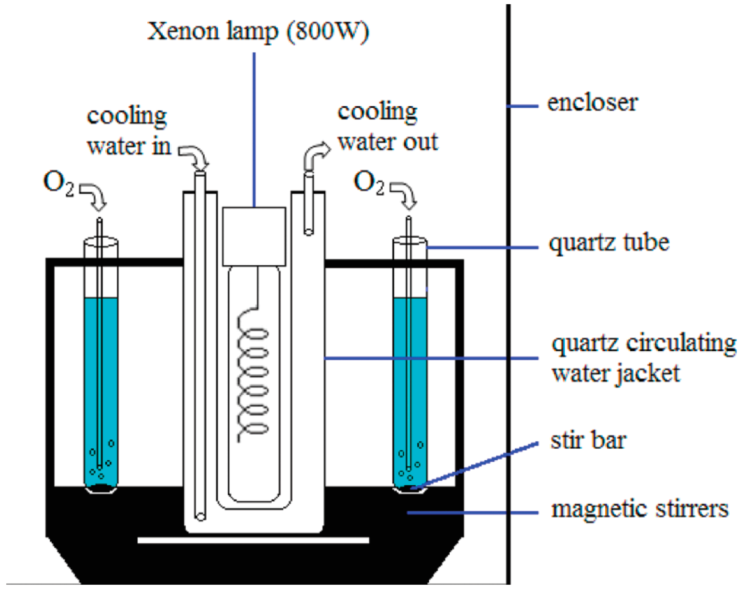
Zheng et al. [13] fabricated HFs through the template method using cotton fibers. The prepared material had a varying percentage of anatase/rutile, depending on the calcination temperature (450, 500, 550, 600, 650, 700, and 750 °C). For the photocatalytic evaluation, 50 mg of HFs was immersed in 50 mL of a 10 mg/L MB solution, and after a 30 min stirring for the establishment of adsorption/desorption equilibrium, oxygen was bubbled into the reactor, under simulated sunlight (Xenon lamp) and constant stirring (Figure 3). At certain intervals, 5 mL of the suspension was separated from the catalyst by centrifugation for 20 min at 9000 rpm, and the absorbance value of the supernatant was measured at 664 nm. The results showed that at 450 °C, TiO2 is in the anatase phase, and its activity is relatively low. With the increase in the calcination temperature to 600 °C, anatase partially transforms to rutile with a weight fraction of 2.93%, showing the best MB degradation of 94.96%. Further calcination temperature increment to 750 °C led to rutile content increase to 44.21%, but the activity decreased.
Wongcharoen et al. [14] report an interesting decrease in the photocatalytic activity of the kapok-template-derived THFs after their Fe doping. First, 50 mg of TiO2 HFs was added to 50 mL of 5 ppm MB and stirred in the dark for 1 h, followed by white LED irradiation (20 W) for 6 h. MB was degraded by 67%, 66%, 55%, and 49% for THF, with 1%-Fe-THF, 3%-Fe-THF, and 5%-Fe-THF, respectively. According to these results, although Fe doping could narrow the band gap of THFs and transfer their photocatalytic activeness to the visible light region, high levels of Fe dopants were found to serve as a recombination center for electrons and holes, instead of electron scavenger sites, thus inhibiting photocatalytic activity.
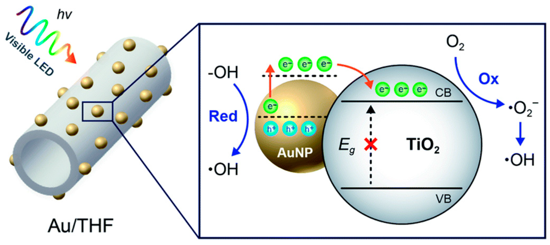
The kapok-template-derived Au/TiO2 HFs [15] were also tested photocatalytically under one Vis-LED lamp (50 W) situated 10 cm away. First, 100 mg of the photocatalyst sample was immersed in 100 mL of 10 mg/L (2.70 × 10⁻⁵ M) MB solution (catalyst dosage 1 g/L). Under Vis-LED irradiation for 8 h, the MB solution is reported to have self-degraded by 30% due to photolysis. In the dark, its absorbance decreased by 1% and 8% for THF and Au/THF, respectively, while no adsorption was noticed for P25. In the presence of THFs and Au/THFs, excluding the self-degradation and adsorption effect, MB was degraded by 46% and 88%, respectively. All reactions were found to follow the pseudo-first-order kinetics, with kAu/THF being 19.98 × 10⁻² h−1, almost three-fold greater than that of THF (7.53 × 10⁻² h−1). In general, the Au-impregnated THFs exhibited double photocatalytic activity and almost 3 times faster reaction than the bare THFs. The proposed mechanism is shown in Figure 4, where the Au nanoparticles absorb the visible light via the surface plasmon resonance (SPR) effect, and photogenerated e are injected into the conduction band of the molecule TiO2, leaving holes behind in the Au nanoparticles. The electrons in the CB of THF react with O2 to produce superoxide anion radicals (O2) and, eventually, the highly oxidative hydroxyl radicals (OH). The holes oxidize the adsorbed H2O or hydroxide anions (OH) to more OH, which subsequently degrade by oxidizing the MB molecules.
In the most recent publication, Nb2O5 HFs and Nb2O5/GO HFs were prepared with the spinning method and evaluated under UVc light (multi-vapor halogen lamp 150 W), against MB [16]. The tests took place in a reactor of 500 mL working volume, 10 mg/L MB concentration (pH = 11), with a module holding fixed HFs of 6 cm in length, each one containing 28.7 mg Nb2O5, representing a catalyst concentration of 57.4 mg/L. MB concentration was determined using a UV-Vis spectrometer at the maximum absorption of 670 nm. After 210 min of irradiation, photo degradation of 66.4% was achieved by the pristine Nb2O5 HFs, compared to the 100% achieved by the GO-coated Nb2O5 HFs. This impressive performance can be attributed to the π unpaired electrons of GO, which delay the recombination of electron-hole pairs, facilitating, therefore, the formation of superoxide radicals and enhancing the catalyst efficiency. The GO-coated Nb2O5 HFs were successfully reused for four reaction cycles (240 min), exhibiting, therefore, long-term stability.
Although Abdullah et al. [17] refer to their photocatalytic application against MB as a membrane one, it is actually a batch one, since no data regarding flow experimental conditions are provided (membrane active surface, permeability, feed flow rate, permeate flow rate, rejection, etc.). The batch photoreactor hosted a module consisting of 16 bundles of the spinning/sintering-prepared TiO2/PVDF HFs, sealed into a PVC tube with the aid of epoxy resin. The module was immersed in 400 mL of the 1 mol/L MB solution and left for 20 min in the dark to obtain the adsorption equilibrium. A UV lamp (175 W, 100 mW/cm2) was placed at a distance of 10 cm above the glass reactor cell. The residual concentration of MB was measured at 30 min intervals, with a complete decolorization to be reported after 90 min. The 1st-order kinetic constants were 0.0591, 0.0295, 0.0188, and 0.0100 for the PVDF, with 3 wt% TiO2/PVDF, 6 wt% TiO2/PVDF, and 9 wt% TiO2/PVDF, respectively, showing, as expected, increasing effectiveness with the TiO2 content.

2.2. Methyl Orange (MO)

Another common model pollutant used for photocatalytic efficiency evaluation is MO. Papageorgiou et al. [18] report the supportive application of spinning-derived Ca-alginate-TiO2 HFs in a flow membrane photocatalytic reactor, although they are not used as membranes but as TiO2 powder immobilizers. Batch experiments took place using (a) the HFs’ hydrogel form (non-porous) and (b) the highly porous HFs’ formed by sc-CO2 drying. The porous Ca alginate/TiO2 fibers exhibited high MO removal efficiency, attributed to their increased surface area and porosity. They achieved a MO degradation rate faster than their non-porous analogs, as well as than P25 TiO2. Therefore, a 31 cm2 HF surface was removed within 220 min at 90% of a 20 mM MO solution, while their non-porous analogs achieved the same goal at 325 min. According to the literature, the corresponding time for a 60 mM MO solution was 140 min for the porous sc-CO2 dried HFs and 240 min for the TiO2 P25. The irradiation sources were 4 UVA lamps (9 W), placed at a distance of 3 cm from the outer side of the photoreactor, emitting near-UV radiation (315–380 nm) with a peak at 365 nm, providing a light intensity of 2.1 mW/cm2.
A set of TiO2/copper nanocomposite HFs, derived from a spinning procedure using alginate as a bio-polymer, was also photocatalytically evaluated by Theodorakopoulos et al. [19] in a batch procedure, examining in parallel the effect of the presence of dissolved O2, as well as of its total absence. A cell containing 30 mL of 6.3 ppm MO solution and 75 mg of ceramic HFs in pieces of 5 mm length and 0.7 mm diameter was used to measure the MO adsorption capacity in the dark, as well as the photocatalytic efficiency and kinetics of MO degradation under UV irradiation. The cell was placed in a rectangular black box photoreactor (50 cm × 40 cm × 30 cm) at a distance of 5 cm from the illumination system, consisting of 4 T8 lamps (15 W) (350–390 nm, light intensity of 0.5 mW/cm2, and photon flux of 15.5 mmol/m2s) in a parallel symmetric arrangement. The results for 2.5 g/L HFs under 0.5 mW/cm2 were R = 67.8% (Inert, 6.3 ppm, 2 h), R = 64.8% (O2, 10 ppm, 3 h), R = 62.5% (O2, 15 ppm, 3 h), and R = 60.5% (O2, 18 ppm, 3 h).
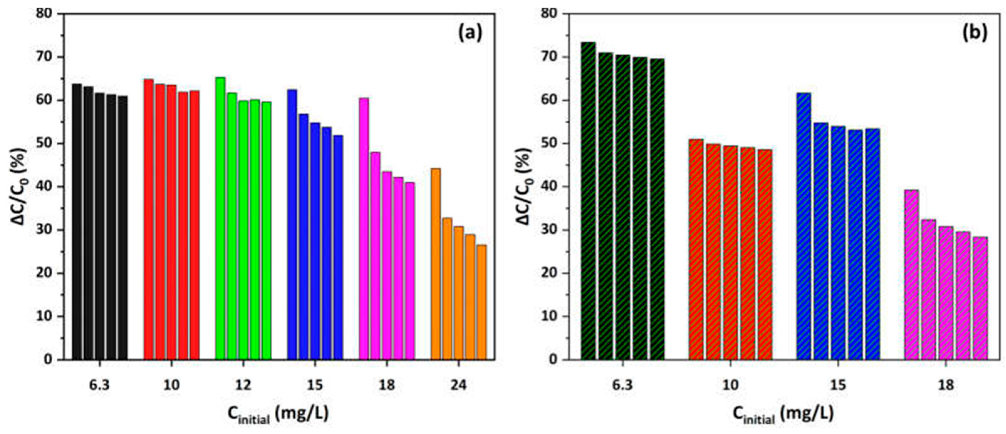
Later, the group replaced the alginate polymer in the manufacturing process with PVDF [20] and evaluated the new TiO2/Copper HFs under the same illumination conditions. Before the irradiation, a 3 h O2 bubbling saturated the MO solution, and a 3 h He bubbling totally depleted it of O2. At lower MO concentrations, the available active sites prove sufficient to accommodate the pollutant molecules, but with the concentration increment, they become saturated, reducing, therefore, the overall efficiency. The resulting copper nanostructures were found to facilitate the photocatalytic process, acting both as a sink for the photogenerated electrons (metallic copper) and in parallel could form CuO/TiO2 heterojunctions, improving the electron-hole separation [21,22]. The Cu-CuO/TiO2 HFs proved photocatalytically active, resulting in R = 65.3% (O2, 12 mg/L, 3 h) and R = 73.5% (Inert, 6.3 mg/L, 3 h). Although the degradation rate decreased slightly at higher concentrations, the photocatalyst could be regenerated and reused for over five successive cycles, maintaining 92% of its initial performance at concentrations up to 15 mg/L (Figure 5).

2.3. Diphenhydramine (DP) Pharmaceutical

The nanocarbon-based TiO2 HFs incorporating (a) nanotubes (CNT), (b) fullerenes (C60), and (c) graphene oxide (GO), as well as HFs with bare TiO2 and P25, were tested in the photodegradation of DP under near-UV/Vis (λ > 350 nm) and VIS irradiation [23]. All were derived from the spinning method using alginate biopolymer. For VIS experiments, a cut-off long pass-filter was used (λ > 430 nm), and the photon flow entering the reactor was 50 mW/cm2 for near-UV/Vis and 6 mW/cm2 for VIS. The batch experiments were performed in a quartz cylindrical reactor filled with 7.5 mL of solution containing 100 mg/L (3.40 × 10⁻⁴ mol/L) DP at room temperature (25 °C) with a HF photocatalyst loading of 1.0 g/L, considering the composite content in these fibers (56 wt.%). A peristaltic pump was used to continuously supply the DP aqueous solution to the photoreactor at a flow rate of 0.15 mL/min. Among all the carbon-containing photocatalysts, the GO–TiO2-4 showed the best performance with a pseudo-first-order constant rate of 126 × 10−3 min−1 under near UV/Vis, leaving CNT–TiO2-4 at the second place (75 × 10−3 min−1), followed by P25 (56 × 10−3 min−1). The same trend was met under visible light irradiation, with the advanced performance attributed to the π unpaired electrons of GO, which delay the recombination of electron-hole pairs.

2.4. Nonyphenol (NP)

The toxic organic chemical, Nonyphenol, being an endocrine disruptor, was used to evaluate the photocatalytic activity of dual-layer TiO2/PVDF HFs. The DLHFs were fabricated via a single-step co-extrusion of two different dope solutions through a triple orifice spinneret. Although referred to as “membranes”, Dzinun et al. [24] tested them under batch conditions in a module holding 20 HFs of 23.5 cm and a total effective area of 248 cm2, which was potted into a PVC tube using epoxy resin. The feed solution of 10 ppm was prepared by dissolving 30 mg of nonylphenol in a 3 L mixture of H2O and acetonitrile (9:1). The module was immersed in the feed solution and irradiated by UVA light, with its temperature increasing, therefore, gradually to about 45 °C. During the photodegradation experiment, 2 mL of the reaction solution was removed every 30 min and analyzed using HPLC coupled with a fluorescence detector. During the 4 h illumination, the concentration of NP decreased from 10 to 1 ppm for the 0.2 TiO2/PVDF HFs and from 10 to 0.2 ppm for the 0.7 TiO2/PVDF HFs in 330 min. For the 0.5 TiO2/PVDF HFs and the 1 TiO2/PVDF HFs, NP was not detected in the solution after 330 min and 150 min, respectively. The degradation rate for the best performing HF was Kapp = 0.0173 min−1.

2.5. Pesticides and Pharmaceuticals

The commercially available herbicide paraquat Gramoxone (GMX) was used for the photocatalytic efficiency evaluation of the kapok-template-derived TiO2 HFs [25]. First, 50 mg of the THFs was immersed in 100 mL of 10 ppm GMX solution and left in the dark under stirring, followed by UV light irradiation using one UV lamp (6 W, λ = 365 nm). Then, 3 μL of the suspension was collected every 1 h, and after centrifugation, the degradation was assessed by measuring the change in the absorbance at the wavelength of 257 nm. Blank experiments in the absence of a catalyst showed no photolysis of the pesticide, as well as no sorption in the dark. The highest pseudo-1st-order degradation rate (1.39 × 10⁻³ min−1) was found for THFs calcined at 450 °C and gradually decreased as the calcination temperature increased under UV light irradiation for 480 min.
Another photocatalytic application of HFs was about treating 8 pharmaceuticals [26] (namely: carbamazepine (CBZ), diclofenac, (DCF), iopromide (IOP), gemfibrozil (GEM), metoprolol (MET), sulfamethoxazole (SMX), trimethoprim (TMP), and warfarin (WAR)), which occurred in real groundwater and secondary wastewater effluent at concentrations in the range of μgL−1 to ngL−1. The groundwater came from a well of approximately 30 m depth, whereas the secondary wastewater effluent came from a bioreactor treating municipal wastewater. These 2 water matrices exhibit different complexity in terms of their main characteristics (pH, conductivity, volatile and total suspended solids, chemical oxygen demand, ammonium, nitrite, nitrate, and total phosphorus). Then, 90 PVDF/TiO2 HFs of 70 cm length were immersed in the 0.5 L vessel, accommodating 114 mg of TiO2 immobilized on the PVDF dual-layer HF, corresponding, therefore, to a concentration of 57 mgTiO2/L (referred to 2 L of solution recirculating through the reactor), which is comparable to 50 mgL−1 of reference TiO2 Degussa. Dark adsorption tests of 30 min were followed by irradiation of the reaction medium by a UV lamp (40 W, λ = 254 nm). Conventional heterogeneous photocatalysis blank tests using suspended TiO2 Degussa P25 catalyst (25–300 mg/L) also took place for comparison reasons, as well as photolysis in the absence of a catalyst. Three of the selected pharmaceuticals (diclofenac, iopromide, and sulfamethoxazole) were rapidly photolyzed and were not involved in the following photocatalytic experimental procedure. For the remaining 5, the photocatalytic transformation followed pseudo-1st-order kinetics, and the results, in general, revealed an efficiency of the synthesized HFs comparable to that of P25, with the latter remaining less preferable due to the limitations concerning the unimmobilized catalyst’s separation (centrifugation) and reusability.

2.6. Bisphenol A (BPA)

Βisphenol A (4,40-isopropylidenediphenol) is a chemical monomer used in the production of plastics like polysulphone, polycarbonate, and epoxy resins, commonly present in everyday products, that has been accused of being endocrine disruptive, resulting in metabolic kinetics changes, chromosomal aberrations, and DNA damage [27].
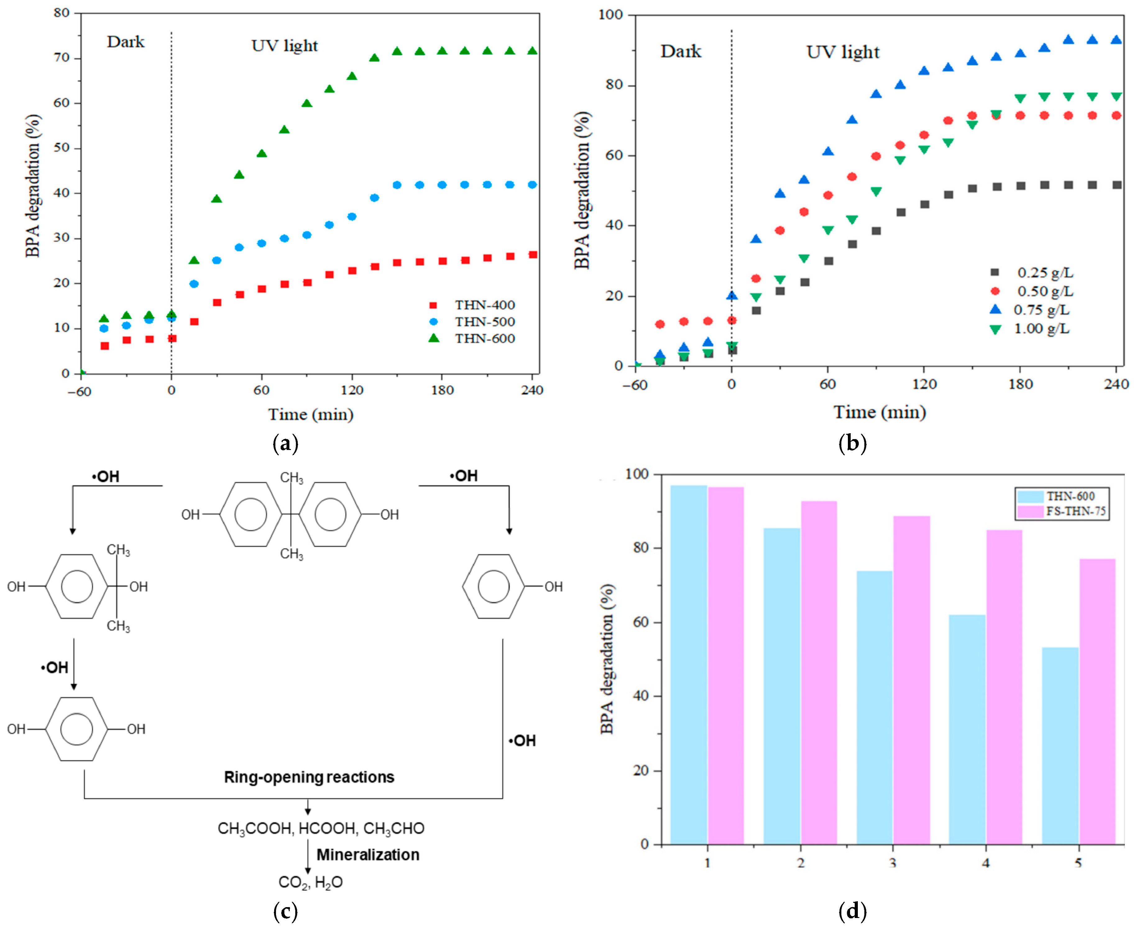
The photocatalytic ability of the electrospun TiO2 Hollow Nanofibers (THNs) was tested as a means of BPA photodegradation under the illumination of one 3.0 mW/cm2 UV lamp (λ = 312 nm, 30 W) positioned 15 cm above the reaction beaker [28]. The THNs were filtered in a Buchner to form a self-standing film, but this film was only used as a photocatalyst immobilizer, not a membrane (even though it was published in the Membranes journal [28]). Investigation regarding the prepared catalyst with the highest performance took place in a 10 mg/L BPA solution, followed by an investigation regarding the optimum catalyst dosage. Every 15 min, 10 mL of the sample aliquot was collected and analyzed by HPLC. After 4 h of constant irradiation, THN-400, THN-500, and THN-600 successfully degraded 26.5%, 42%, and 71.5% of BPA, respectively (Figure 6a). Then, 0.75 g/L proved to be the best performing dosage for the best performing HFs calcinated at 600 °C (Figure 6b). Regarding the degradation mechanism, HPLC/MS analysis of photocatalytic degradation of BPA recognized the presence of 4-isopropanolphenol, phenol, and hydroquinone intermediates, further degradation of which led to short-chain aliphatic compounds. The authors propose the degradation mechanism in Figure 6c, where the oxidation of BPA begins with the •OH radical attacking the electron-rich C3 of the phenyl group. A cleavage of the phenyl groups occurs, forming phenol and 4-isopropanolphenol, and the oxidation of the latter produces hydroquinone. Final ring- opening with •OH leads to simple aliphatic compounds (acetic acid and formic acid) and mineralization into carbon dioxide and water. Finally, the recyclability of THN-600 and FS-THN-75 after five cycles of reaction is shown in Figure 6d.
Another case of publication in the Membranes journal, although no membrane experiments are presented, is that of the N-doped TiO2 catalyst immobilization on HFs, described by Kamaludin et al. [29]. Having a band gap of 2.64 eV, the catalyst is reported to have mitigated 90% of the BPA under UV and 81.6% under visible light irradiation.

2.7. Rohdamine B (RhB)

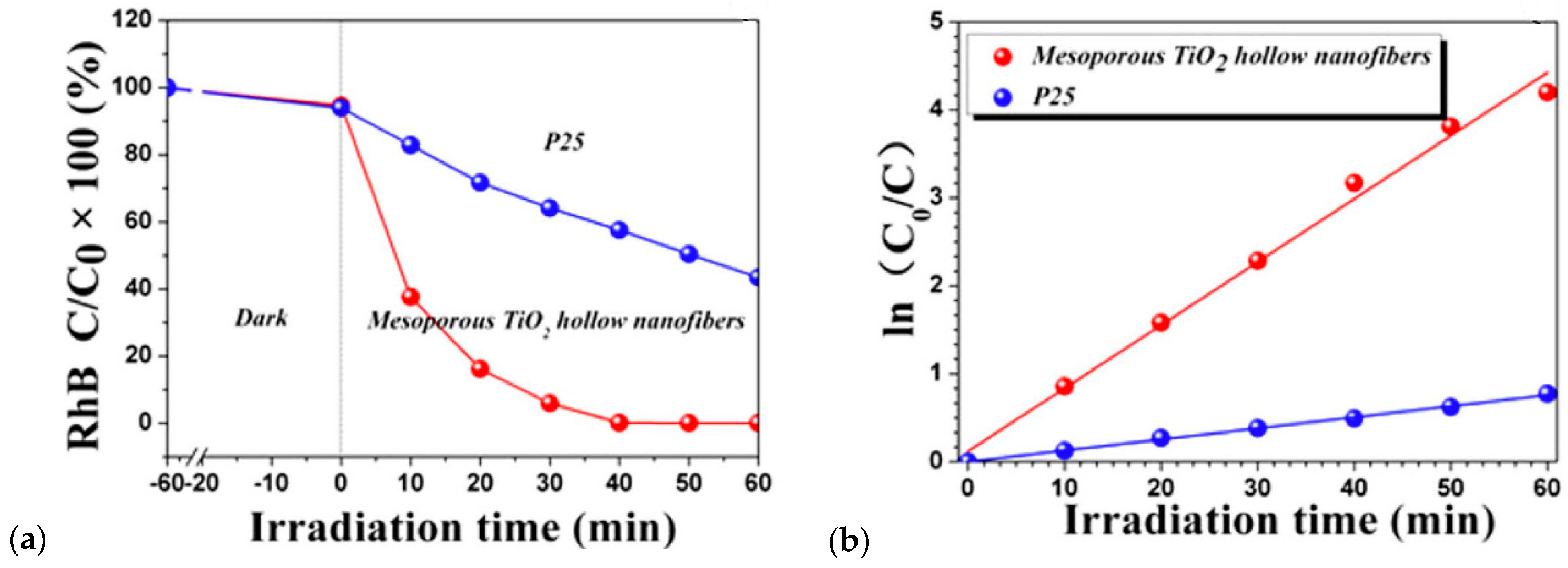
The photocatalytic properties of the mesoporous TiO2 HFs prepared through electrospinning by Hou et al. [30] were evaluated by the decomposition of RhB dye in a quartz tubular reactor having a 300 W Xenon lamp (λ > 320 nm). First, 1.2 mg of RhB and 40 mg of the HFs were dispersed in 120 mL of deionized water and stirred in the dark for 60 min for the adsorption equilibrium. The overall RhB degradation efficiency was found to be 99.5% for the TiO2 HFs, which was almost 2.5 times higher than that of P25 (Figure 7), with the corresponding pseudo-first-order kinetic constant rates being k = 0.071 min−1 and k = 0.010 min−1 for the mesoporous TiO2 hollow fibers and P25, respectively.

3. Gas-Phase Photocatalytic Applications

3.1. H2 Production

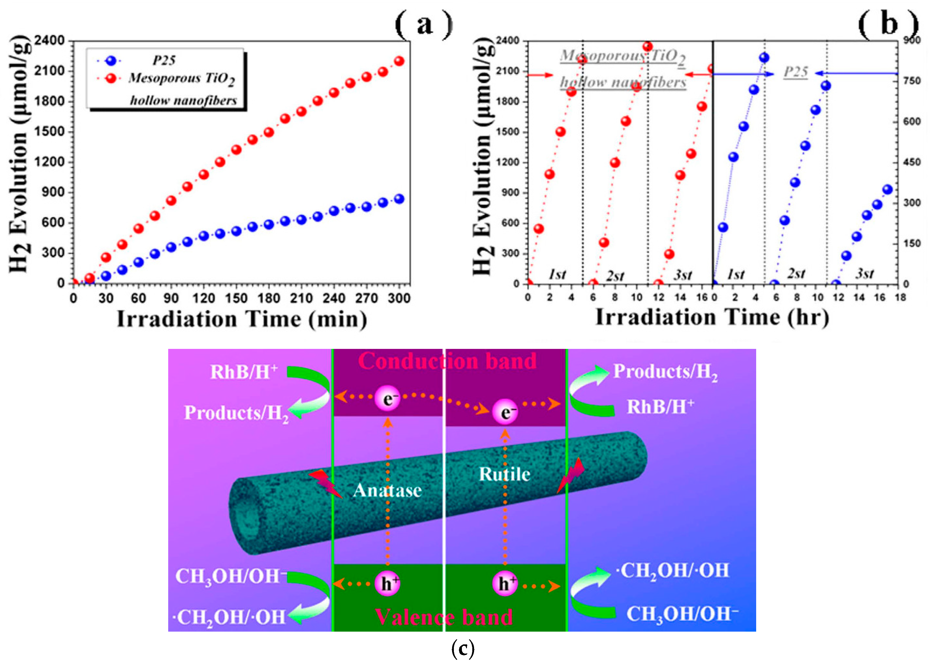
The previously mentioned electrospun TiO2 HFs [30] were also evaluated for photocatalytic H2 production. The reaction took place again in a quartz annular reactor with a 300 W Xenon lamp (λ > 320 nm), a vacuum pump, gas collection, a recirculation pump, and a water-cooled condenser. First, 0.1 g of the HFs was suspended in 40 mL of DI water and methanol (3:1), and the hydrogen evolution was monitored by an online gas chromatograph. TiO2 HFs exhibited a stable H2 release rate of ~499.1 μmolg−1·h−1, which is much higher than that of P25, 197.8 μmolg−1·h−1 (Figure 8a). The reusability of TiO2 HFs and P25 was tested under identical experimental conditions. Commercial P25 evidently declined after 3 cycles, while TiO2 HFs showed no noticeable decrease, exhibiting, therefore, stability (Figure 8b). The proposed photocatalytic mechanism is depicted in Figure 8c, where the mixed-phase junction of anatase and rutile leads to a functional improvement in the charge transfer and recombination avoidance.

3.2. Gas Formaldehyde Degradation

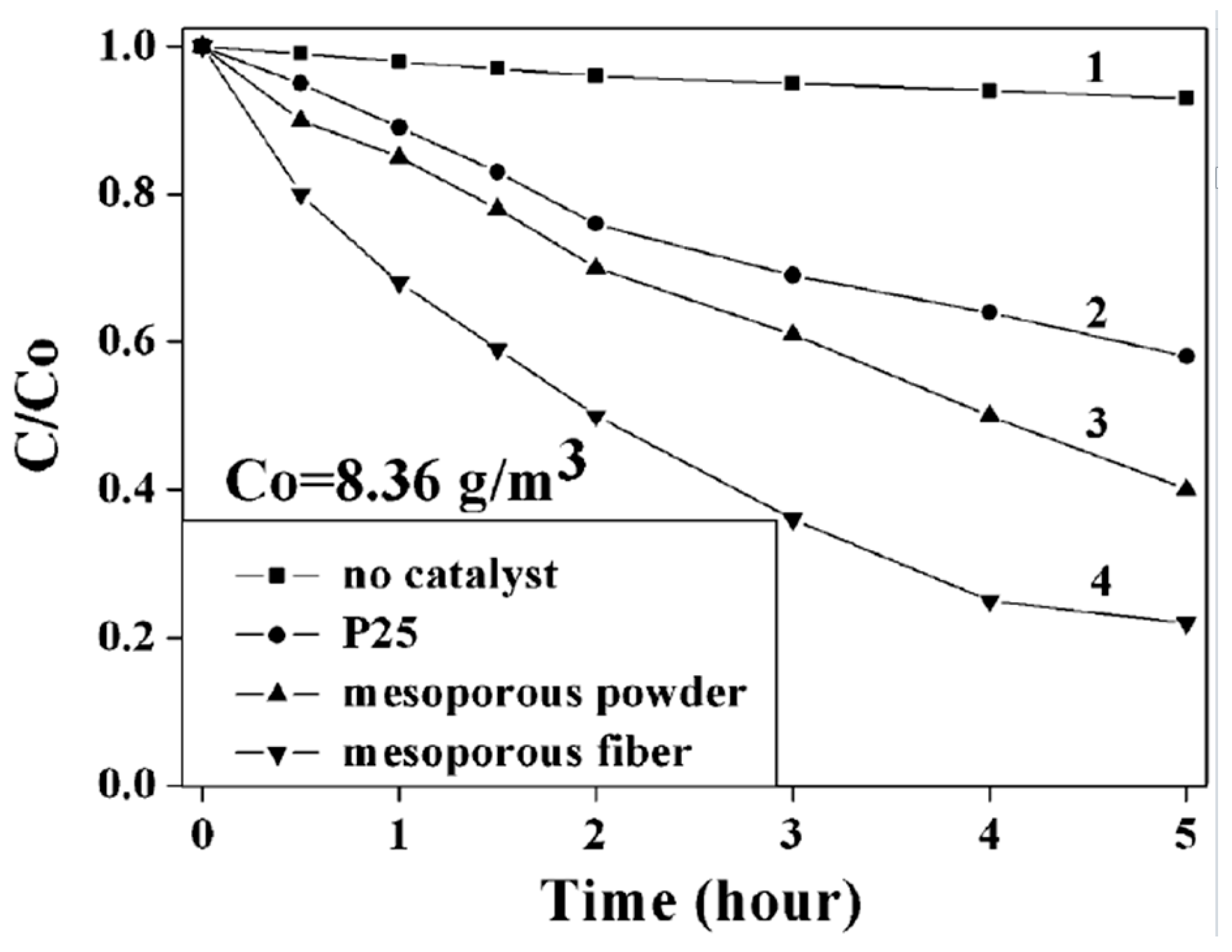
The photodecomposition of formaldehyde, a common gas pollutant, was also studied [12] using 1.0 mg of the TiO2 HFs prepared by an unusual electrospinning process, where inorganic precursor Ti(OBu)4 solution was added in the outer spinneret tube, while an immiscible liquid (machine oil) was poured into the inner capillary. The HFs were placed in a 250.0 mL glass bottle and filled with gaseous formaldehyde by vaporization of 5 μL 37% formaldehyde solution to produce an initial concentration of formaldehyde of 8.36 g/m3. After 1 h in the absence of light, the gas–solid adsorption process reached equilibrium, and the photoreactor bottle was irradiated with the mercury lamp. The phenol-spectrophotometry method was applied to determine the concentration change of gaseous formaldehyde at various UV irradiation times. Therefore, after 5 h, formaldehyde was degraded only up to 42% and 50% in the presence of P25 and mesoporous TiO2 powders, respectively (control experiments), while in the presence of TiO2 HF, gaseous formaldehyde was degraded to CO2 and H2O up to 80%, under the same conditions (Figure 9).

3.3. Gas Ammonia (NH3) Degradation

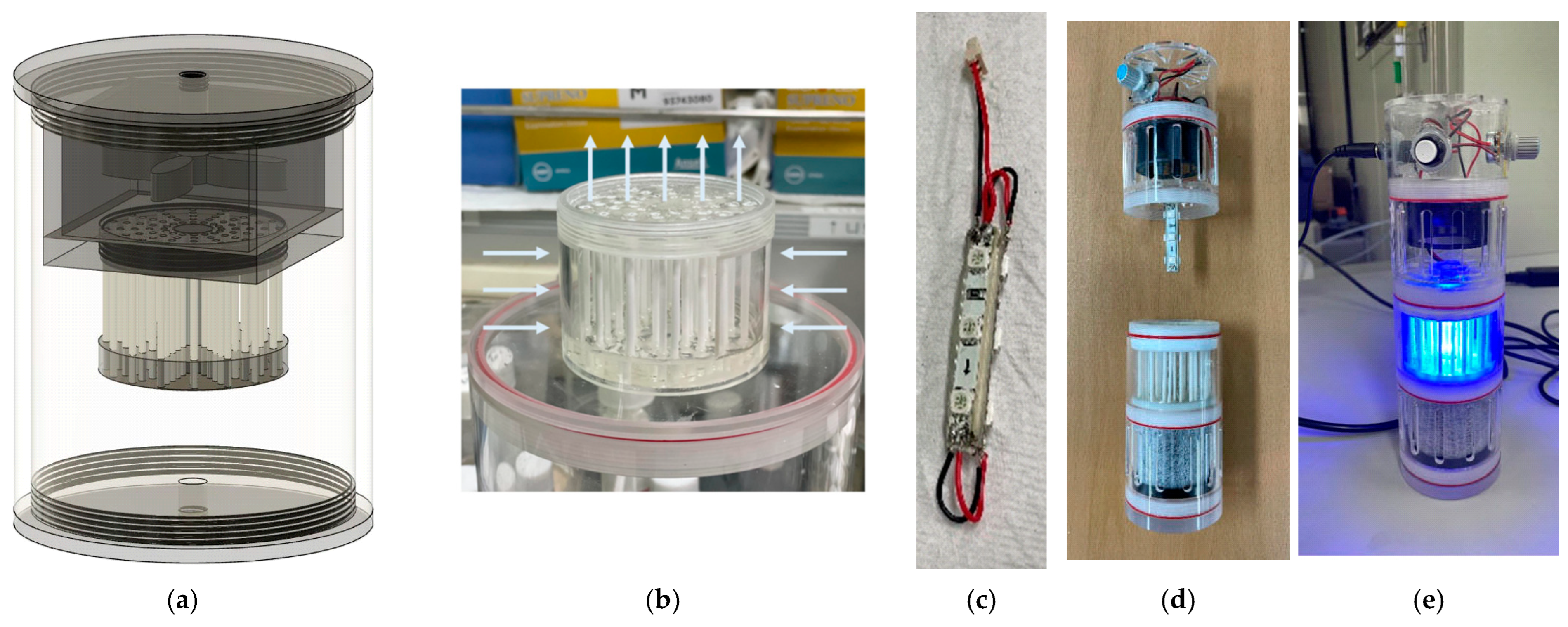
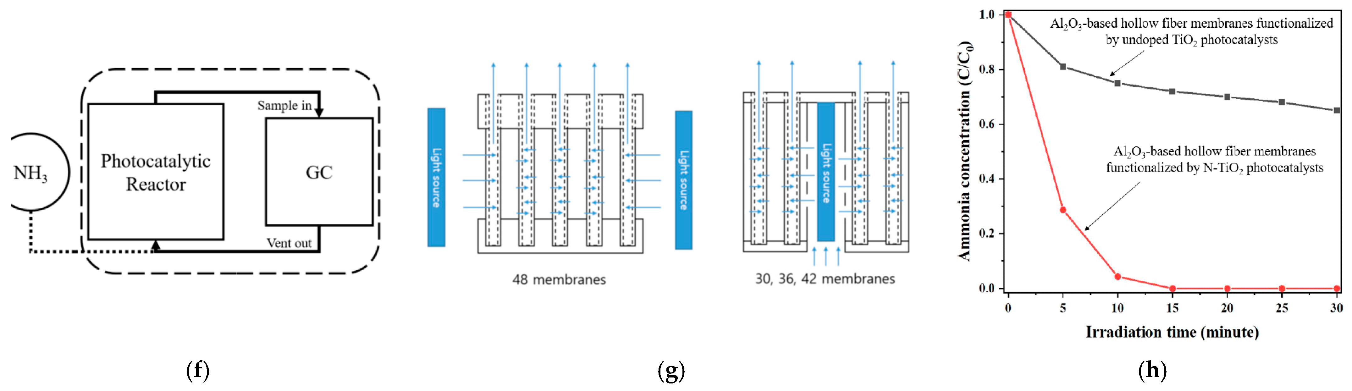
Al2O3 HFs were dip-coated in TiO2 and N-TiO2 and evaluated for photodegradation of NH3 under UV and white light in the custom-made photoreactor in Figure 10a–e, which could accommodate 30, 36, 42, or 48 HFs with surface areas of 8.430 × 10⁻³, 1.012 × 10⁻², 1.180 × 10⁻², and 1.349 × 10⁻² m2, respectively [7]. The system was supplied with NH3 gas (5%, He balanced), with the flow rate not given, and the test was performed in a closed loop as seen in Figure 10f. The authors claim that their HFs are used as membranes (HFMs) with two different dead-end filtering configurations (Figure 10g), but this remains uncertain since no data for gas NH3 permeability are provided. Although under UV, both doped and undoped TiO2 degraded the NH3 in 20 min, exhibiting similar behavior, under VIS, the efficiency of N-TiO2 proved to be far elevated (Figure 10h).

4. Membrane Flow Experiments

Apart from the photocatalytic applications in batch experiments, where the HFs play the role of simple immobilizers of the photocatalyst, only a few publications represent them as real membrane filters under flow conditions. Since every prepared membrane is different in terms of macroscopic characteristics (shape, dimensions, etc.), only an appropriate and specialized membrane reactor can accommodate it, which is, most of the time, custom-made.

4.1. Methylene Blue (MB)

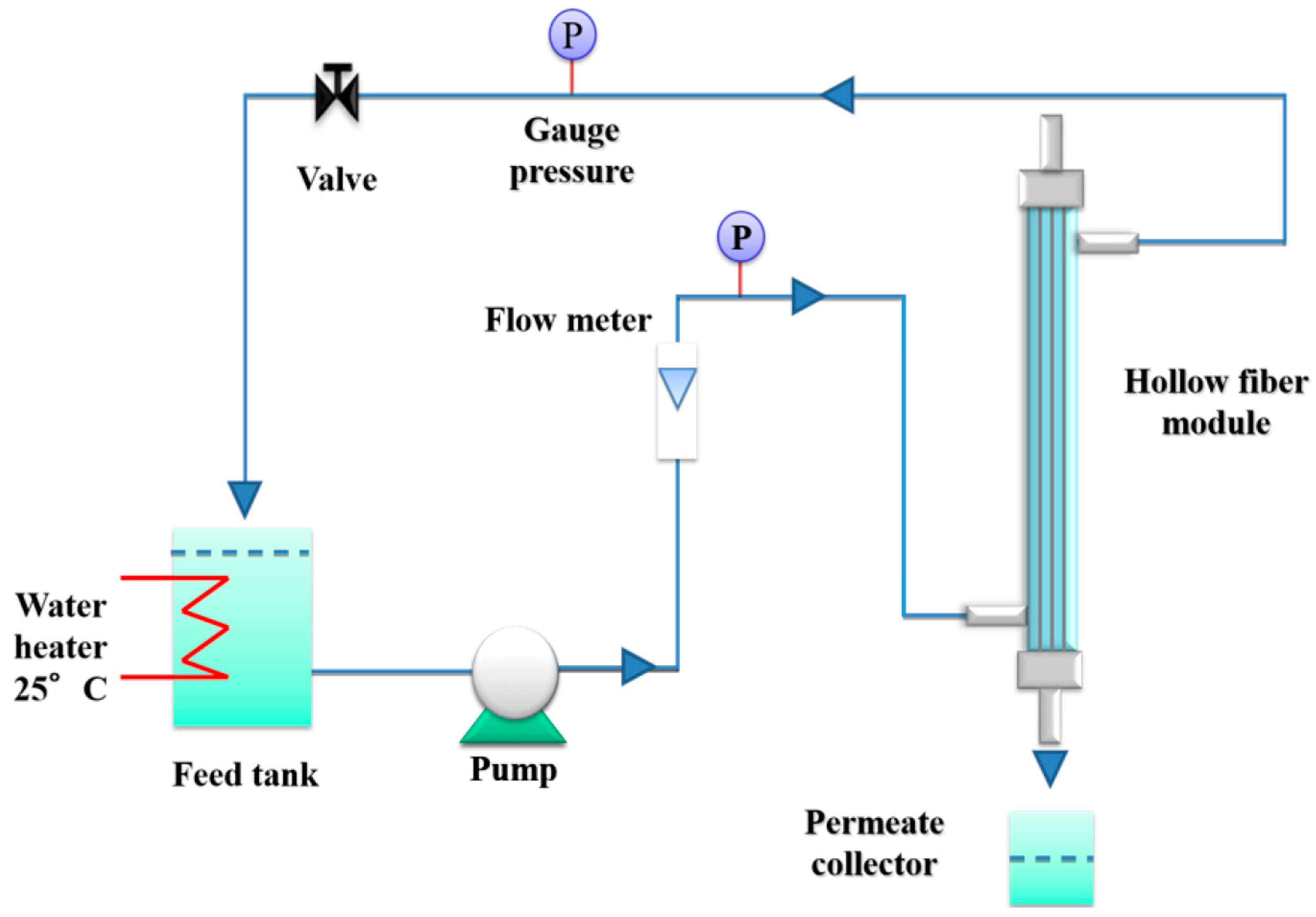
Polyethersulfone (PES) spinning-fabricated ultrafiltration HFMs, modified through the introduction of TiO2 nanoparticles in the polymeric dope, were tested photocatalytically against MB [31]. Pure water permeability measurements were carried out in crossflow mode with a configuration of water passing from the outside to the inside using a pump, as depicted in Figure 11. The lab-made module contained 3 HFs of 20 cm (surface area 0.0036 m2), and the water permeability values measured were from 51 to 81 L/m2hbar for the various HFMs produced. Contrary to the membranes’ water permeability tests, their photocatalytic activeness was tested only qualitatively under batch conditions and not under flow ones, against the MB solution under UV-A light (18 W, λmax at 365 nm) for 2 h at 0.6 mW/cm2. The same experimental setup (Figure 11) was used by the group when testing their PVDF/TiO2 nanoparticles HFMs [32]. The photocatalytic experiments this time were held under crossflow conditions against 250 mL 10 μm/L MB by recirculation of both retentate and permeate streams into the feed tank. The transmembrane pressure was kept at 0.5 bar and the flow velocity at 0.06 m/s. The membrane module was irradiated by two of the above-described lamps, with the distance between them and the module being 6 cm, and the estimated light intensity reaching the membrane surface being 2.7 mW/cm. Before irradiation, the HFMs were left overnight for the MB adsorption equilibrium. MB degradation was also studied in synthetic seawater, with the rejection being 97% in both cases.
Hwang et al. [33] prepared, through the common spinning/phase inversion method, PMIA/TiO2 HFMs with various TiO2 contents. For the flux measurements of the membranes, a custom-made setup accommodated two 20 cm long HFMs, with one of the side ends fixed and sealed in a polyurethane tube. Dead-end experiments with outside–inside configuration provided an initial water flux permeance of 207.5 L/m2h at the absence of TiO2, which gradually decreased upon incorporation of TiO2 nanoparticles due to a reduction in the pore size. However, as the TiO2 content increased, the flux gradually recovered, reaching 132.6 L/m2h at 4.76 wt% TiO2 concentration, a behavior attributed to surface hydrophilicity, which facilitated water transport despite the narrowing of pore structure. Nevertheless, the photocatalytic testing took place under batch conditions by employing 7 mg of each prepared sample against 125 mL of 10 mg/L MB under UV light placed at a 10 cm distance. The results exhibited photocatalytic efficiency increasing with the TiO2 content.
Chakraborty et al. are examining their synthesized HFMs under flow conditions with MB and Chlorhexidine Digluconate (CHD) pharmaceutical compound for their photocatalytic performance under simulated solar light of 1500 W [34]. The feed flow rate was 8 L/min, and the trans membrane pressure varied from 40 to 60 kPa by partially closing the retentate valve. The average permeability within the 40–60 kPa pressure range was measured after the pressure stabilization. The membrane glass module used was 12 cm long and 1.2 cm in diameter, with 4 HFMs fixed tightly into it, having two inlets and two outlets. The “outside–inside” configuration was chosen for the operation of the membrane, as the skin layer was on the outer side of the fiber. The length of the fiber used was 10 cm, and the available surface area was 7.22 cm2.

4.2. Bisphenol A (BPA)

Cu2O was embedded into PVDF to generate Cu2O/PVDF DLHFMs with a narrow bandgap of 2.2 eV, which were tested for BPA 10 mg/L photocatalytic degradation under visible light [35]. Investigation of the best Cu2O loading and outer dope extrusion flow rate was carried out. The high porosity membranes had huge water fluxes up to 13,891 L/m2h measured in a custom-made setup under the operating pressure of 0.05 Mpa. Then, 0.50 Cu2O/PVDF eliminated successfully about 75% of the 10 ppm BPA in 360 min in batch (not flow) photocatalytic experiments under visible light irradiation, without the copper element being leached.
A recent work combined copper (II) oxide–vanadium tetrasulfide (CuO–VS4) with PVDF DLHFMs for the removal of Bisphenol A [36]. Water flux analysis was conducted in crossflow mode, at 1 bar, with a 10 cm membrane, and the obtained values varied from 17.07 (bare PVDF) to 39.42 L/m2h (0.25 PVDF/CuO–VS4 DLHF). Then, 0.25 PVDF/CuO–VS4 DLHF degraded. Photodegradation of 1 mg/L BPA under visible light achieved 70.24%, while both photodegradation and rejection of BPA could achieve up to 73.19% after 4 h.
BPA has also been photodegraded by HFMs produced using the low-cost kaolin powder (Al2Si2O5(OH)4) as an Al2O3 source substitute of the expensive and high-sintering-temperature-demanding (over 1300 °C) commonly used α-Alumina. The ceramic HFMs prepared by Sharif et al. [37] were decorated with Ag-doped TiO2 photocatalysts by dip coating in an Ag/TiO2 nanoparticle solution for 30 s (TM-30), 60 s (TM-60), 90 s (TM-90), and 120 s (TM-120). The band gap for the Ag-doped TiO2 photocatalysts was found to be 2.9 eV, while the band gap of the Ag/TiO2-coated membrane was 2.5 eV. The HFMs’ water permeability values were found to decrease with the increase in the Ag/TiO2 nanoparticle content, from 625.76 L/m2∙h for the TM-0 to 75.78 L/m2∙h for TM-120, a behavior attributed to the presence of nanoparticles inside the membrane pores. Despite their testing for water permeability under flow conditions, the HFMs (length of 8 cm) were tested photocatalytically under batch conditions, using a BPA solution (100 mL, 10 mg/L) under a 100 W Xe lamp (visible light), with the sample of the maximum catalyst loading depredating the 88% of BPA removal within 270 min, according to the following equations:
TiO2 + hv → e + h+
Ag0 + hv →Ag˙
e (cb) + h+ (vb) → TiO2 + hv
e (cb) + Agn+ → Agn−1
Agn−1 + h+ (vb) →TiO2 + Agn+
h+ (vb) + H2O →H+ + HO˙
Agn−1 + O2→Ag n+ + O2˙
O2˙ + BPA→CO2 + H2O
HO˙ + BPA→CO2 + H2O
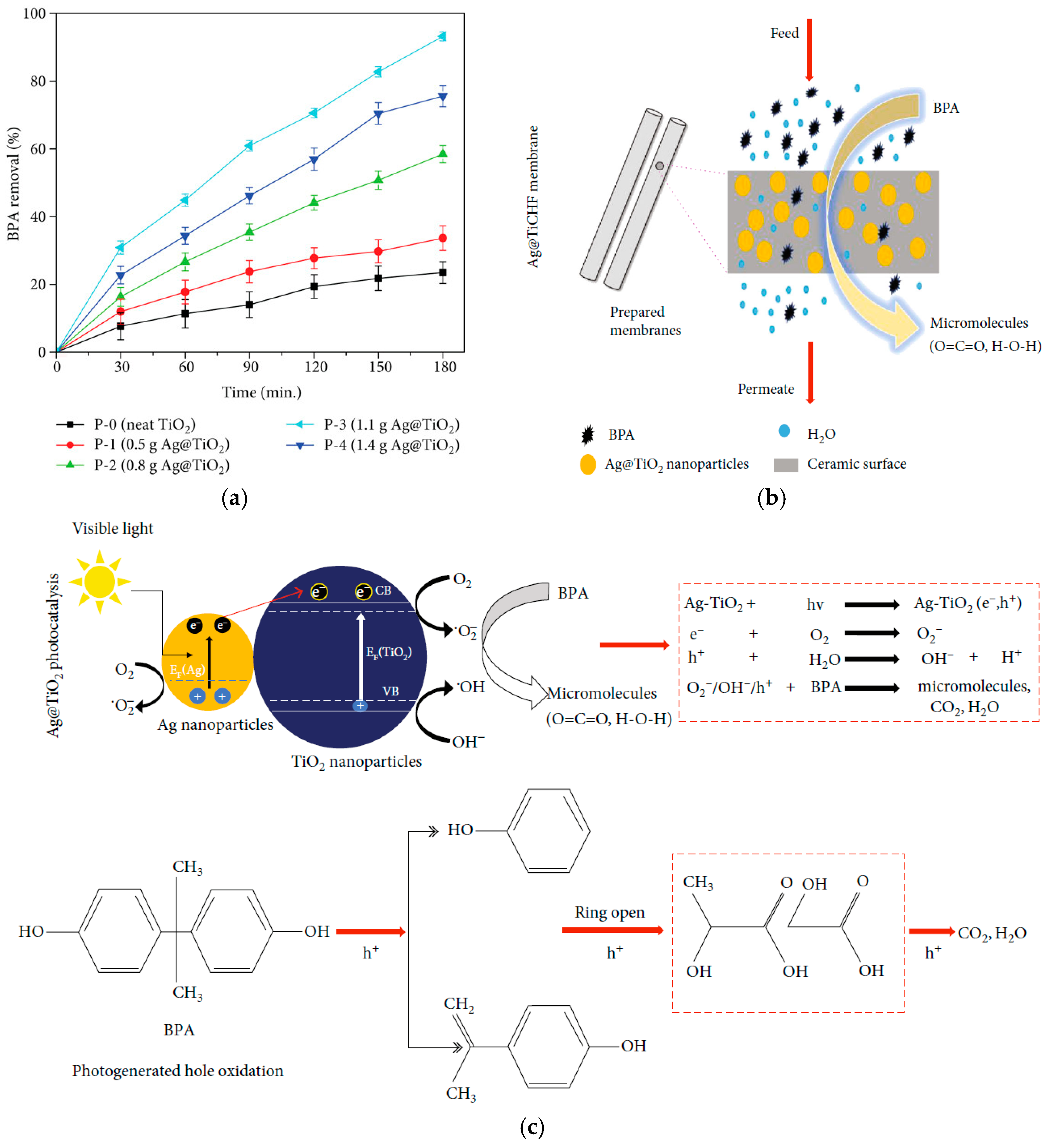
The next year, Sharilf et al. [38] report the 93.21% degradation of BPA within 180 min under batch conditions by the HFM sample bearing 1.1 g Ag@TiO2 photocatalyst (Figure 12a), although the membranes’ flux has been measured in a pilot-scale crossflow filtration device under 2.0 bar pressure. The possible mechanism of BPA degradation is shown in Figure 12c. The presenting impurity (silver ions) in the TiO2 narrows its band by lowering the conduction band edge and, therefore, shifting its absorption frequency into the visible light region. Under the Xe lamp, electrons jump from valence to conduction band inside the Ag@TiO2 nanoparticles, creating photoelectrons (e) and positive holes (h+), which react with oxygen and water to produce free radicals (O2 and -HO), which in turn break down BPA into CO2 and H2O (Figure 12c). These micromolecules (CO2 and H2O) finally penetrate the membrane (Figure 12b).
CuxO photocatalyst was deposited onto the surface of PVDF HFMs by radio frequency (RF) magnetron sputtering, and their photocatalytic efficiency was evaluated under VIS light (LED lamp, 100 W) against 2, 5, and 10 mg/L BPA solutions [39]. The reactor accommodated a bundle of 20 strands of HFMs of 10 cm, potted into a PVC tube using epoxy, and although it worked under flow conditions to give water permeability values of ~17–37 L/m2h, the experiments underwent batch conditions. Then, 91% removal of BPA in real-treated sewage wastewater was achieved using 20 mL/min Cu2O/PVDF HFM after 360 min of irradiation, while 71% of the catalyst was regenerated after 3 consecutive cycles.

4.3. Acid Orange 7 (AO)

TiO2 HFMs prepared through the common spinning/sintering method were actually tested photocatalytically under dead-end flow conditions against AO7 [40,41]. One end of the HF was sealed with epoxy resin, with the other being connected to a 1.5 kPa vacuum applied across the membrane as the driving force. The permeate stream was collected in a cold trap and immersed in a liquid nitrogen dewar. Four UV-A lamps (8 W, 330–370 nm emission) were placed concentrically 15 cm away from the quartz reactor vessel, containing 25 mL of 20 ppm AO7 (pH 6.5), and 50 mg of the HFMs (membrane surface area: approximately 1.5 × 10⁻⁴ m2) were immersed. UV intensity was measured at 0.17 mW/cm2. The results exhibited a strong dependence of the degradation percentage on the pyrolysis temperature, as the 500 °C carbon HF gives no degradation (0%), the 600 °C carbon HF gives 43%, and it increases to 90.4% for the 550 °C carbon HF. The best performing sample proved to be the high proportion of the anatase TiO2 phase (79%). Further experiments revealed the presence of a critical pyrolysis temperature window (550–575 °C) and a pyrolysis time window (6–8 h) requirements for a full surface exposure of the anatase TiO2 nanoparticles. The investigation of the calcination duration effect on the photocatalytic activity revealed that although both the 3 h and 6 h calcinated membranes (4 cm in length) exhibited a rejection over 99%, their permeability differed a lot under UV light for both water and AO7 solution. The 3 h calcinated membrane exhibited flux values of 6.9 (H2O/dark), 12.9 (H2O/UV), 4.8 (AO7/dark) and 7.9 (AO7/UV) Lm–2h–1, which were generally 5- to 10-fold higher than those of the 6 h membrane, showing photo-induced super-hydrophilicity and defouling potential under UV light due to the photo-activation of TiO2.

4.4. Nonylphenol (NP)

A set of TiO2/PVDF DLHFMs with various TiO2 weight ratios was prepared to test the effect of TiO2 loading and UV irradiation intensity on their antifouling properties [42]. A bundle of 20 HFs (~23.5 cm, 248 cm2) was potted into a PVC tube using epoxy resin and immersed in a 7 L nonylphenol (NP) solution under UVA radiation of 8 or 36 W (365 nm), with 0.33 and 18.2 W/cm2 of light intensity, respectively, measured at a distance of 4.5 cm between the two membrane modules. Water permeate was collected by creating a 0.5 bar vacuum at the permeate side. The results revealed a by-far better photocatalytic performance of the 0.2% TiO2/PVDF sample, which, when further tested for 4.5 h under 8 and 36 W, showed the high activation of the TiO2 nanoparticles at higher energy.

4.5. Antifouling/Self-Cleaning

In the typical filtration process, membrane fouling is a critical issue, and photocatalysts have been developed to address it.
In order to verify the performance of their TiO2 HFs in real-world applications, Zhang et al. [40] exposed them to residential sewage, consisting of dissolved and suspended organic pollutants. This led inevitably to severe membrane fouling. Their permeability and photocatalytic activity were evaluated in a custom-made setup with a 25 mL glass vessel surrounded by four UV-A lamps (8 W, emitting at 330–370 nm), at 15 cm from each other. As such, it was estimated that about only 5% of the UV light emitted from the four lamps reached the reactor, accommodating membranes of 5 cm length (active surface area: 1.9–2.1 cm2). Prior to photocatalytic experiments, the membrane flux of DI water was measured in a dead-end filtration mode, with one end of the membrane being sealed with silicone gel and the other end being connected to a permeate collector and a vacuum pump, which applied across the membrane a driving force of 0.9 bar. The DI water permeance was as high as 87.7 L m−2 h−1, decreasing to only 5.6 L m−2h−1 after the wastewater filtration, a reduction of 93.6%. In the presence of UV irradiation, the membrane’s flux increased to 12.2 Lm−2 h−1 (more than double), indicating a measurable photocatalytic antifouling action.
Asymmetric Al2O3 HFMs were prepared by the spinning/phase inversion/sintering (1400 °C) technique using polyethersulfone (PESf) as a blending polymer and externally decorated with 1–3 wt.% CuO/CeO2 photocatalyst providing synergistic redox properties [43]. The membrane was tested with a feed velocity of 3.0 m/s and trans membrane pressure of 2 bars. The pristine HFM’s pure water permeation was 118.5 L/m2hbar and reduced to 107.4 L/m2hbar at the introduction of 10% BSA solution in the feed stream, while the corresponding values for the CuO/CeO2 catalyst HFM were 56.5 L/m2hbar and 19.0 L/m2hbar. After being exposed to UV irradiation in batch conditions for antifouling and cleaning, the catalyst-HFM exhibited an increase in BSA permeance to 30.5 L/m2hbar, a phenomenon linked also with the photo-induced hydrophilicity of CuO/CeO2 once UV-irradiated.
Another case of Al2O3 HFMs was those coated with electrospinning-derived polyacrylonitrile nanofibers (NF) incorporating graphitic carbon nitride (g-C3N4) [44]. Tested in a crossflow filtration mode, the NF-g-C3N4/Al2O3 membrane showed pure water flux at 816 L/m2h, high oilfield-produced water (OPW) permeate flux at 640 L/m2h, and oil rejection at 99%. After 3 operational cycles, it maintained a high permeate flux (577 L/m2h) and oil rejection (97%) as a result of the g-C3N4 nanofiber coating, which degrades the captured oil contaminants under 180 min UV irradiation (30 W lamp, peak at 312 nm).
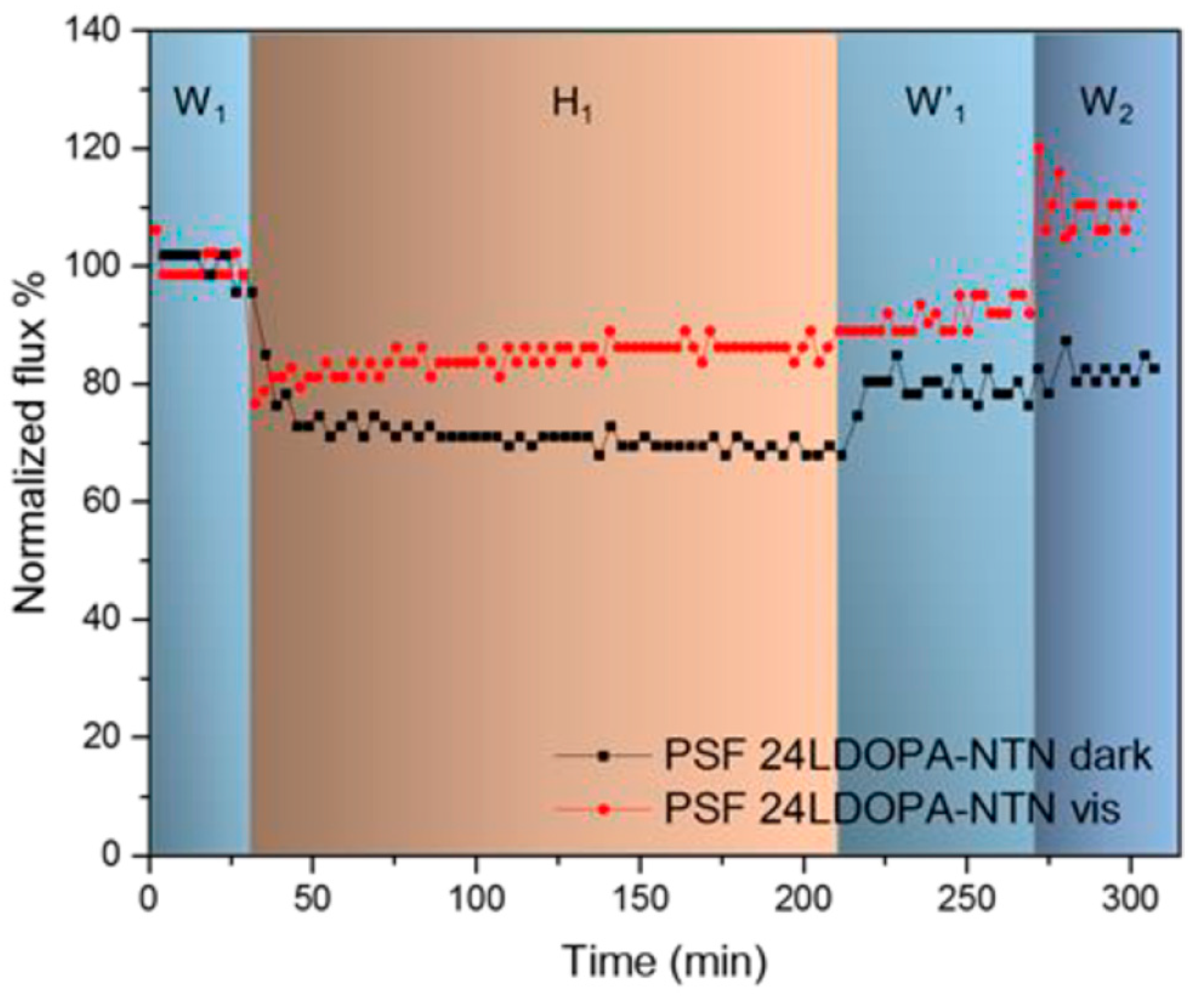
Although current HFMs’ antifouling approaches are mostly based on UV irradiation, Wan et al. [6] report the synthesis of an HFM with self-cleaning property under visible light. Polysulfone (PSF) HFM was spinning-prepared, and N-TiO2 NPs were surface grafted via LDOPA chemical bonding. Despite its long-term instability, the modified HFM (namely PSF 24LDOPA-NTN) was able to recover completely to its initial pure water permeate flux under VIS light after being exposed to humic acid (20 mg/L, pH = 7) as a model foulant (Figure 13).
Oilfield-produced water (OPW) was the foulant again in the case of TiO2-WO3@GO/PVDF DLHFMs [45], which were fabricated via the co-extrusion/phase inversion method with varying (0, 1, 3, 5) wt.% of the TiO2-WO3@GO photocatalyst. A bundle of 20 HFMs of 10 cm in length was potted into a PVC tube, and their photocatalytic performance was evaluated in terms of total organic carbon (TOC) degradation under visible light for 6 h using one 100 W LED bulb. The 3 wt.% loaded membrane showed the best TOC rejection of 98.62% after 6 h of operation, with water permeate and OPW flux of 99.51 L/m2h and 76.54 L/m2h, respectively. After the five operational cycles, the pure water and OPW flux for the 3 wt.% HFM were 94.02 L/m2h and 69.92 L/m2h, respectively, while only 24.86 L/m2h and 12.58 L/m2h were observed for the non-photocatalytic (0 wt%) membrane. The antifouling and self-cleaning ability results were attributed to the electron storage of WO3 within the system, improving, therefore, the absorptive capacity of TiO2 in the visible range, while the GO promoted the electron-hole transfer, decreasing the band gap value of 2.32 eV to 2.16 eV.

5. Conclusions and Future Work

A comprehensive presentation of the photocatalytic applications of HFs and HFMs took place, and, as seen, the majority of the publications use the HFs as photocatalyst immobilizers [12,13,14,15,16,17,18,19,20,21,22,23,24,25,26,27,28,29,30]. Fewer publications utilize them as a photocatalytic membrane, conducting photodegradation under flow conditions [6,7,34,40,41,42,43,44,45], while some, although providing water permeability values, did not utilize them in a photocatalytic filtration [28,32,33,35,36,37,38]. In a few cases, the authors make a misleading use of the word “membrane”, although no filtering process is described in the article [17,26,28,29]. There was also a case in which, although the title refers to “photocatalytic TIO2/PVDFM for endocrine disrupting compounds degradation”, no photocatalytic experiment under either flow or batch conditions was presented [46].
Concerning the photocatalyst employed, a lack of diversification is observed. Almost all studies mentioned have used pure TiO2 or titania-based hetero-structures, with the exceptions of Cu2O [35,39], CuO–VS4 [36], CuO/CeO2 [43], gC3N4 [44], and Nb2O5 [16]. In the field of irradiation, the works using visible light are limited to the Fe-doped TiO2 [14], Au-doped TiO2 [15], Cu2O/PVDF [35,39], CuO–VS4 [36], the Ag-doped TiO2 [37,38], the TiO2/carbon nanocomposites (GO, C60, and CNTs) [23], N-doped TiO2 [6,7,29] and the TiO2-WO3@GO photocatalyst [45]. Nevertheless, there are some studies using Xenon lamps for simulated solar light [13,30,34], which is an attempt close to visible light.
For completeness reasons, we have to mention a group of publications that utilize TiO2 on HFMs [47,48,49,50,51,52] and characterize them thoroughly in terms of pore-blocking and filtration-performing, but never irradiate and actually use them in photo-excited reactions, being therefore out of the scope of the present review and the hosting journal.
Another profound observation is that the, up-to-now, reported gas-phase photocatalytic applications of HFs appear limited to H2 production [30], formaldehyde [12], and ammonia degradation [7]. Nevertheless, beyond water splitting (to produce H2) and the oxidation of volatile organic compounds (formaldehyde and ammonia), conventional gas-phase photocatalytic systems include applications such as CO2 reduction into green solar fuels, the degradation of nitrogen oxides, as well as the synthesis of ammonia, which could be perfectly combined with hollow fibers as photocatalyst immobilizers. Furthermore, photocatalytic hollow fiber membranes could also be applied in gas-phase applications. Till now, to the best of the author’s knowledge, very few articles study the use of photocatalytic membranes in gas-phase applications, and none has published work that utilizes photocatalytic HFMs in a gas-phase application. Consequently, this uncovered field of research would be of great interest in future work, as it would benefit from the remarkable advantages of hollow structures in enhancing photocatalytic activity. These advantages include (a) the large surface area of the HFs/HFMs, which provides sufficient accessible sites for the gas molecules to firstly adsorb and then react photocatalytically, (b) the multiple light scattering within the hollow cavity of the HF, which enhances the light-harvesting efficiency, and (c) the simultaneous, single-step reaction and separation that HFMs, like all catalytic membranes, offer.
In the experimental field, a general ascertainment is that there is no uniform protocol or standard way of evaluating the efficiency of a catalyst. Every group of authors uses a different evaluation setup, different catalyst quantity, different model or real wastewater pollutant, and different illumination system with a different irradiation density reaching the catalyst surface. There are cases where no specific information about the lamps used is provided, such as irradiation density, λmax, watt, or distance from the catalyst [7,29,35,36,43]. This, as expected, turns every single experiment into a unique and specialized one, making any attempt at comparison with others almost impossible.
Additionally, in the field of HFMs, there seems to be a lack of energy consumption data presentation. When referring to membranes, it is important to know the operation energy cost, arising as a sum of the pump energy for fluid recirculation and the irradiation lamps [4]. This can be a meaningful suggestion for future work in the field.

Funding

This research received no external funding.

Data Availability Statement

No new data were created or analyzed in this study. Data sharing is not applicable to this article.

Conflicts of Interest

The author declares no conflicts of interest.

Abbreviations

The following abbreviations are used in this manuscript:
HFHollow fiber
HFMHollow fiber membrane
THFTiO2 hollow fibers
MBMethylene blue
MOMethyl orange
AO7Acid orange 7
DLHFDual layer hollow fibers
PEIpolyethyleneimine
PMIAPoly(m-phenylene isophthalamide
PESPolyethersulfone
PSFPolysulfone
PVDFpolyvinylidene fluoride
HPLChigh performance liquid chromatography
RhBRohdamine B
BPABisphenol A
DPDiphnylamine
OPWOilfield produced water
LDOPA3-(3,4-dihydroxyphenyl) lalanine
TOCTotal organic carbon
GO Graphene oxide
CNTCarbon nanotube
GMXGramoxone
CBZCarbamazepine
DCFDiclofenac
IOPIopromide
GEMGemfibrozil
METMetoprolol
SMXSulfamethoxazole
TMPTrimethoprim
WARWarfarin
NPNonyphenol
SPRSurface plasmon resonance

References

  1. Athanasekou, C.; Moustakas, N.G.; Morales-Torres, S.; Pastrana-Martínez, L.M.; Figueiredo, J.L.; Faria, J.L.; Silva, A.M.T.; Rodriguez, J.M.D.; Romanos, G.E.; Falaras, P. Ceramic photocatalytic membranes for water filtration under UV and visible light. Appl. Catal. B Environ. 2015, 178, 12–19. [Google Scholar] [CrossRef]
  2. Athanasekou, C.; Morales-Torres, S.; Likodimos, V.; Romanos, G.E.; Pastrana-Martinez, L.M.; Falaras, P.; Faria, J.L.; Figueiredo, J.L.; Silva, A.M.T. Prototype composite membranes of partially reduced graphene oxide/TiO2 for photocatalytic ultrafiltration water treatment under visible light. Appl. Catal. B Environ. 2014, 158–159, 361–372. [Google Scholar] [CrossRef]
  3. Romanos, G.E.; Athanasekou, C.; Likodimos, V.; Aloupogiannis, P.; Falaras, P. Hybrid Ultrafiltration/Photocatalytic Membranes for Efficient Water Treatment. Ind. Eng. Chem. Res. 2013, 52, 13938–13947. [Google Scholar] [CrossRef]
  4. Athanasekou, C.; Romanos, G.E.; Katsaros, F.K.; Kordatos, K.; Likodimos, V.; Falaras, P. Very efficient composite titania membranes in hybrid ultrafiltration/photocatalysis water treatment processes. J. Membr. Sci. 2012, 392–393, 192–203. [Google Scholar] [CrossRef]
  5. Romanos, G.E.; Athanasekou, C.P.; Katsaros, F.K.; Kanellopoulos, N.K.; Dionysiou, D.D.; Likodimos, V.; Falaras, P. Double-side active TiO2-modified nanofiltration membranes in continuous flow photocatalytic reactors for effective water purification. J. Hazard. Mater. 2012, 211–212, 304–316. [Google Scholar] [CrossRef] [PubMed]
  6. Wan, P.; Zhang, Z.; Deng, B. Photocatalytic Polysulfone Hollow Fiber Membrane with Self-Cleaning and Antifouling Property for Water Treatment. Ind. Eng. Chem. Res. 2019, 58, 3339–3348. [Google Scholar] [CrossRef]
  7. Magnone, E.; Hwang, J.Y.; Shin, M.C.; Zhuang, X.; Lee, J.I.; Park, J.H. Al2O3-Based Hollow Fiber Membranes Functionalized by Nitrogen-Doped Titanium Dioxide for Photocatalytic Degradation of Ammonia Gas. Membranes 2022, 12, 693. [Google Scholar] [CrossRef] [PubMed]
  8. Wang, Q.; Dong, Y.; Zhu, J.; Han, J.; Li, Z.; Xu, D.; Fischer, L.; Ulbricht, M.; Ren, Z.; Wang, P. Critical review on emerging photocatalytic membranes for pollutant removal: From preparation to application. Talanta 2025, 287, 127561. [Google Scholar] [CrossRef]
  9. Sun, X.; Tian, J.; Cai, J.; Wang, Y.; He, T.; Qiu, X.; Li, Z.; Bahnemann, D.W.; Pan, J. Photocatalytic Membrane Filtration: Materials, System Optimization, and External Field Enhancement. Energy Environ. Mater. 2025, 8, 70012. [Google Scholar] [CrossRef]
  10. Ibrahim, I.; Elseman, A.M.; Sadek, H.; Eliwa, E.M.; Abusaif, M.S.; Kyriakos, P.; Belessiotis, G.V.; Mudgal, M.M.; Abdelbasir, S.M.; Elsayed, M.H.; et al. Membrane-Based Photocatalytic and Electrocatalytic Systems: A Review. Catalysts 2025, 15, 528. [Google Scholar] [CrossRef]
  11. Binazadeh, M.; Rasouli, J.; Sabbaghi, S.; Mousavi, S.M.; Hashemi, S.A.; Lai, C.W. An Overview of Photocatalytic Membrane Degradation Development. Materials 2023, 16, 3526. [Google Scholar] [CrossRef] [PubMed]
  12. Zhan, S.; Chen, D.; Jiao, X.; Tao, C. Long TiO2 Hollow Fibers with Mesoporous Walls: Sol-Gel Combined Electrospun Fabrication and Photocatalytic Properties. J. Phys. Chem. B 2006, 110, 11199–11204. [Google Scholar] [CrossRef]
  13. Zheng, T.; Tian, Z.; Su, B.; Lei, Z. Facile Method To Prepare TiO2 Hollow Fiber Materials via Replication of Cotton Fiber. Ind. Eng. Chem. Res. 2012, 51, 1391–1395. [Google Scholar] [CrossRef]
  14. Wongcharoen, S.; Chokradjaroen, C.; Panomsuwan, G. Effect of Fe doping on the photocatalytic activity of TiO2 hollow fibers under LED light irradiation. Mater. Sci. Eng. 2020, 773, 012052. [Google Scholar] [CrossRef]
  15. Panomsuwan, G.; Wongcharoen, S.; Chokradcharoen, C.; Tipplook, M.; Jongprateep, O.; Saito, N. Au nanoparticle-decorated TiO2 hollow fibers with enhanced visible-light photocatalytic activity. RSC Adv. 2022, 12, 193–200. [Google Scholar] [CrossRef]
  16. de Paulo Ferreira, E.; Ribeiro, S.R.F.L.; Sousa, T.S.E.; Cardoso, V.L.; Reis, M.H.M. Surface decoration of Nb2O5 hollow fibers by graphene oxide for enhanced photocatalytic degradation of methylene blue. J. Am. Ceram. Soc. 2025, 108, 20176. [Google Scholar] [CrossRef]
  17. Abdullah, N.; Ayodele, B.V.; Nurdiyan, W.; Mansor, W.; Abdullah, S. Effect of Incorporating TiO2 Photocatalyst in PVDF Hollow Fibre Membrane for Photo-Assisted Degradation of Methylene Blue. Bull. Chem. React. Eng. Catal. 2018, 13, 588–591. [Google Scholar] [CrossRef]
  18. Papageorgiou, S.K.; Katsaros, F.K.; Favvas, E.P.; Romanos, G.E.; Athanasekou, C.P.; Beltsios, K.G.; Falaras, O.I.T.P. Alginate fibers as photocatalyst immobilizing agents applied in hybrid photocatalytic/ultrafiltration water treatment processes. Water Res. 2012, 46, 1858–1872. [Google Scholar] [CrossRef]
  19. Theodorakopoulos, G.V.; Romanos, G.E.; Katsaros, F.K.; Papageorgiou, S.K.; Kontos, A.G.; Spyrou, K.; Beazi-Katsioti, M.; Falaras, P. Structuring efficient photocatalysts into bespoke fiber shaped systems for applied water treatment. Chemosphere 2021, 277, 130253. [Google Scholar] [CrossRef] [PubMed]
  20. Theodorakopoulos, G.V.; Papageorgiou, S.K.; Katsaros, F.K.; Romanos, G.E.; Beazi-Katsioti, M. Investigation of MO Adsorption Kinetics and Photocatalytic Degradation Utilizing Hollow Fibers of Cu-CuO/TiO2 Nanocomposite. Materials 2024, 17, 4663. [Google Scholar] [CrossRef]
  21. Athanasekou, C.; Romanos, G.E.; Papageorgiou, S.K.; Manolis, G.K.; Katsaros, F.; Falaras, P. Photocatalytic degradation of hexavalent chromium emerging contaminant via advanced titanium dioxide nanostructures. Chem. Eng. J. 2017, 318, 171–180. [Google Scholar] [CrossRef]
  22. Theodorakopoulos, G.; Athanasekou, C.; Romanos, G.E.; Papageorgiou, S.K. Current photocatalytic systems for intensified water purification applications. In Handbook of Smart Photocatalytic Materials, Fundamentals, Fabrications, and Water Resources Applications; Elsevier: Amsterdam, The Netherlands, 2020; pp. 231–264. [Google Scholar]
  23. Pastrana-Martínez, L.M.; Morales-Torres, S.; Papageorgiou, S.K.; Katsaros, F.K.; Romanos, G.E.; Figueiredo, J.L.; Faria, J.L.; Silva, A.M.T. Photocatalytic behaviour of nanocarbon–TiO2 composites and immobilization into hollow fibres. Appl. Catal. B Environ. 2013, 142–143, 101–111. [Google Scholar] [CrossRef]
  24. Dzinun, H.; Othman, M.H.D.; Ismail, A.F.; Puteh, M.H.; Rahman, M.A.; Jaafar, J. Photocatalytic degradation of nonylphenol using co-extruded dual-layer hollow fibre membranes incorporated with a different ratio of TiO2/PVDF. React. Funct. Polym. 2016, 99, 80–87. [Google Scholar] [CrossRef]
  25. Wongcharoen, S.; Panomsuwan, G. Easy synthesis of TiO2 hollow fibers using kapok as a biotemplate for photocatalytic degradation of the herbicide paraquat. Mater. Lett. 2018, 228, 482–485. [Google Scholar] [CrossRef]
  26. Paredes, L.; Murgolo, S.; Dzinun, H.; Othman, M.H.D.; Ismail, A.F.; Carballa, M.; Mascolo, G. Application of immobilized TiO2 on PVDF dual layer hollow fibre membrane to improve the photocatalytic removal of pharmaceuticals in different water matrices. Appl. Catal. B Environ. 2019, 240, 9–18. [Google Scholar] [CrossRef]
  27. Thiruvenkatachari, R.; Kwon, T.O.; Moon, S. Application of Slurry Type Photocatalytic Oxidation-Submerged Hollow Fiber Microfiltration Hybrid System for the Degradation of Bisphenol A (BPA). Sep. Sci. Technol. 2005, 40, 2871–2888. [Google Scholar] [CrossRef]
  28. Jafri, N.N.M.; Jaafar, J.; Aziz, F.; Salleh, W.N.W.; Yusof, N.; Othman, M.H.D.; Rahman, M.A.; Ismail, A.F.; Rahman, R.A.; Khongnakorn, W. Development of Free-Standing Titanium Dioxide Hollow Nanofibers Photocatalyst with Enhanced Recyclability. Membranes 2022, 12, 342. [Google Scholar] [CrossRef]
  29. Kamaludin, R.; Rasdi, Z.; Othman, M.H.D.; Kadi, S.H.S.A.; Nor, N.S.M.; Khan, J.; Zain, W.N.I.M.; Ismail, A.F.; Rahman, M.A.; Jaafar, J. Visible-Light Active Photocatalytic Dual Layer Hollow Fiber (DLHF)Membrane and Its Potential in Mitigating the Detrimental Effects of Bisphenol A in Water. Membranes 2020, 10, 32. [Google Scholar] [CrossRef]
  30. Hou, H.; Shang, M.; Wang, L.; Li, W.; Tang, B. Efficient Photocatalytic Activities of TiO2 Hollow Fibers with Mixed Phases and Mesoporous Walls. Sci. Rep. 2015, 5, 15228. [Google Scholar] [CrossRef]
  31. Simone, S.; Galiano, F.; Faccini, M.; Boerrigter, M.E.; Chaumette, C.; Figoli, E.D.A. Preparation and Characterization of Polymeric-Hybrid PES/TiO2 Hollow Fiber Membranes for Potential Applications in Water Treatment. Fibers 2017, 5, 14. [Google Scholar] [CrossRef]
  32. Galiano, F.; Song, X.; Marino, T.; Boerrigter, M.; Saoncella, O.; Simone, S.; Faccini, M.; Chaumette, C.; Drioli, E.; Figoli, A. Novel Photocatalytic PVDF/Nano-TiO2 Hollow Fibers for Environmental Remediation. Polymers 2018, 10, 1134. [Google Scholar] [CrossRef] [PubMed]
  33. Hwang, G.-I.; Lee, S.; Lee, J.-H.; Moon, J.; Shin, Y.-R.; Baik, D.H.; Jee, M.H.; Jeong, Y.G. TiO2-incorporated poly(m-phenylene isophthalamide) hollow fiber membranes for superior ultrafiltration, mechanical strength, photocatalytic activity in water treatmen. Chem. Eng. J. 2025, 520, 165930. [Google Scholar] [CrossRef]
  34. Chakraborty, S.; Loutatidoua, S.; Palmisano, G.; Kujawa, J.; Mavukkandy, M.O.; Al-Gharabli, S.; Curcio, E.; Arafat, H.A. Photocatalytic hollow fiber membranes for the degradation of pharmaceutical compounds in wastewater. J. Environ. Chem. Eng. 2017, 5, 5014–5024. [Google Scholar] [CrossRef]
  35. Noor, S.H.M.; Othman, M.H.D.; Khongnakorn, W.; Sinsamphanh, O.; Abdullah, H.; Puteh, M.H.; Kurniawan, T.A.; Zakria, H.S.; El-badawy, T.; Ismail, A.F.; et al. Bisphenol A Removal Using Visible Light Driven Cu2O/PVDF Photocatalytic Dual Layer Hollow Fiber Membrane. Membranes 2022, 12, 208. [Google Scholar] [CrossRef]
  36. Zakria, H.S.; Othman, M.H.D.; Borhamdin, S.; Ismail, N.J.; Rahman, M.A.; Jaafar, J.; Puteh, M.H.; Yahaya, N.K.E.M.; Idris, A.; Kurniawan, T.A. PVDF/CuO–VS4 Dual-Layer Hollow Fiber Photocatalytic Membrane for Bisphenol A Removal with Energy Storage Capability. Korean J. Chem. Eng. 2025, 42, 1055–1070. [Google Scholar] [CrossRef]
  37. Shareef, U.; Othman, M.H.D.; Ismail, A.F.; Jilani, A. Facile removal of bisphenol A from water through novel Ag-doped TiO2 photocatalytic hollow fiber ceramic membrane. J. Aust. Ceram. Soc. 2019, 56, 29–39. [Google Scholar] [CrossRef]
  38. Shareef, U.; Waqas, M. Bisphenol A Removal through Low-Cost Kaolin-Based Ag@TiO2 Photocatalytic Hollow Fiber Membrane from the Liquid Media under Visible Light Irradiation. J. Nanomater. 2020, 12, 3541797. [Google Scholar] [CrossRef]
  39. Zakria, H.S.; Othman, M.H.D.; Kamaludin, R.; Jilani, A.; Omar, M.F.; Ayub, M.; Saidin, M.A.R.; Kurniawan, T.A.; Hashim, N.; Yahaya, N.K.E.M.; et al. Removal of bisphenol A from synthetic and treated sewage wastewater using magnetron sputtered CuxO/PVDF thin film photocatalytic hollow fiber membrane. J. Water Process Eng. 2023, 51, 103425. [Google Scholar] [CrossRef]
  40. Zhang, X.; Wang, D.K.; Lopez, D.R.S.; da Costa, J.C.D. Fabrication of nanostructured TiO2 hollow fiber photocatalytic membrane and application for wastewater treatment. Chem. Eng. J. 2014, 236, 314–322. [Google Scholar] [CrossRef]
  41. Wang, D.K.; Elma, M.; Motuzas, J.; Hou, W.-C.; Xie, F.; Zhange, X. Rational design and synthesis of molecular-sieving, photocatalytic, hollow fiber membranes for advanced water treatment applications. J. Membr. Sci. 2017, 524, 163–173. [Google Scholar] [CrossRef]
  42. Dzinun, H.; Othman, M.H.D.; Ismail, A.F.; Puteh, M.H.; Rahman, M.A.; Jaafar, J.; Adrus, N.; Hashim, N.A. Antifouling Behavior and Separation Performance of Immobilized TiO2 in Dual Layer Hollow Fiber Membranes. Polym. Eng. Sci. 2018, 58, 1636–1643. [Google Scholar] [CrossRef]
  43. Abdullah, N.; Rahman, M.A.; Othman, M.H.D.; Ismail, A.F.; Jaafar, J.; Aziz, A.A. Preparation and characterization of self-cleaning alumina hollow fiber membrane using the phase inversion and sintering technique. Ceram. Int. 2016, 42, 12312–12322. [Google Scholar] [CrossRef]
  44. Alias, N.H.; Jaafar, J.; Samitsu, S.; Matsuurae, T.; Ismail, A.F.; Othman, M.H.D.; Rahman, M.A.; Othman, N.H.; Abdullah, N.; Paiman, S.H.; et al. Photocatalytic nanofiber coated alumina hollow fiber membranes for highly efficient oilfield produced water treatment. Chem. Eng. J. 2019, 360, 1437–1446. [Google Scholar] [CrossRef]
  45. Samuel, O.; Khan, A.U.; Kamaludin, R.; Othman, M.H.D.; Kurniawan, T.A.; Imtiaz, A.; Al-Ogaili, M.F.; Usman, J.; Muhammad, M.S.; Abdulkareem, B.; et al. Dual layer hollow fiber photocatalytic membrane based on TiO2-WO3@GO composite with catalytic memory and enhanced anti-fouling and self-cleaning properties for oilfield-produced water treatment. Chem. Eng. J. 2024, 483, 149–220. [Google Scholar] [CrossRef]
  46. Kamaludin, R.; Othman, M.H.D.; Kadir, S.H.S.A.; Rahman, M.A.; Jaafar, J. The morthological properties of photocatalytic TIO2/PVDF dual layer hollow fiber membrane for endocrine disrupting compounds degradation. Malays. J. Anal. Sci. 2017, 21, 426–434. [Google Scholar]
  47. Yu, L.-Y.; Shen, H.-M.; Xu, Z.-L. PVDF–TiO2 Composite Hollow Fiber Ultrafiltration Membranes Prepared by TiO2 Sol–Gel Method and Blending Method. J. Appl. Polym. Sci. 2009, 113, 1763–1772. [Google Scholar] [CrossRef]
  48. Razmjou, A.; Resosudarmo, A.; Holmes, R.L.; Li, H.; Mansouri, J.; Chen, V. The effect of modified TiO2 nanoparticles on the polyethersulfone ultrafiltration hollow fiber membranes. Desalination 2012, 287, 271–280. [Google Scholar] [CrossRef]
  49. Dzinun, H.; DzarfanOthman, M.; Ismail, A.F.; Puteh, M.; Rahman, M.A.; Jaafar, J. Morphological study of co-extruded dual-layer hollow fiber, Membranes incorporated with different TiO2 loadings. J. Membr. Sci. 2015, 479, 123–131. [Google Scholar] [CrossRef]
  50. Abba, M.U.; Man, H.C.; Azis, R.S.; Idris, A.I.; Hamzah, M.H.; Yunos, K.F.; Katibi, K.K. Novel PVDF-PVP Hollow Fiber Membrane Augmented with TiO2 Nanoparticles: Preparation, Characterization and Application for Copper Removal from Leachate. Nanomaterials 2021, 11, 399. [Google Scholar] [CrossRef]
  51. Casetta, J.; Ortiz, D.G.; Pochat-Bohatier, C.; Bechelany, M.; Miele, P. Atomic layer deposition of TiO2 on porous polysulfone hollow fibers membranes for water treatment. Sep. Purif. Technol. 2023, 312, 123377. [Google Scholar] [CrossRef]
  52. Pandey, N.; Bellare, J. Titanium dioxide/graphene oxide blending into polyethersulfone hollow fiber membranes improves biocompatibility and middle molecular weight separation for bioartificial kidney and hemodialysis applications. J. Mater. Chem. B 2025, 13, 9392. [Google Scholar] [CrossRef] [PubMed]
Figure 1. (a) Illustration of the spinning setup, (b) cross-section SEM image of a typical HFM (35 times magnitude), (c) SEM image of the porous network of a typical HFM (200 times magnitude), and (d) SEM image of the outer surface of a typical HFM (1000 times magnitude). ((a) (Reprinted with permission from Ref. [6]. Copyright 2006, American Chemical Society); (bd) Reproduced from open access Ref. [7]).
Photochem 06 00012 g001
Figure 2. Photodegradation kinetics of MB; lines: (1) without photocatalyst, (2) commercial P25 (surface area: 50 m2/g, mean size: 20 nm, phase: anatase/rutile 80/20), (3) mesoporous powders (surface area: 167 m2/g, the pore size was the same as that of the HFs), and (4) mesoporous HFs (surface area: 208 m2/g) (Reprinted with permission from Ref. [12]. Copyright 2006, American Chemical Society).
Photochem 06 00012 g002
Figure 3. Illustration of the reactor setup used for the photocatalytic experiments. (Reprinted with permission from Ref. [13]. Copyright 2012, American Chemical Society).
Photochem 06 00012 g003
Figure 4. Schematic diagram of the MB photocatalytic degradation on Au/THF under Vis-LED irradiation. (Reproduction from reference [15], Copyright 2022, Royal Society of Chemistry).
Photochem 06 00012 g004
Figure 5. % MO photocatalytic degradation by the Cu-CuO/TiO2 nanocomposite under UV-A after 5 cycles at various concentrations in (a) O2-saturated and (b) O2-depleted solutions (natural pH, 25 °C) (Reproduced from open access Ref. [20]).
Photochem 06 00012 g005
Figure 6. (a) Degradation of BPA with different photocatalysts. (b) Degradation of BPA with different photocatalyst dosages. (c) Proposed photocatalytic degradation pathway of BPA. (d) Recyclability of THN-600 and FS-THN-75 at five cycles of reaction. (Reproduced from open access Ref. [28]).
Photochem 06 00012 g006
Figure 7. (a) Photocatalytic degradation of RhB (C0 = 10 mg/L) of mesoporous TiO2 hollow nanofibers and P25 under UV-visible light irradiation. (b) The plot of ln(C0/C) with irradiation time for mesoporous TiO2 hollow nanofibers and P25. (Reproduced from open access Ref. [30]).
Photochem 06 00012 g007
Figure 8. (a) The hydrogen production photocatalyzed by the as-fabricated mesoporous TiO2 hollow nanofibers, as well as P25, under different irradiation times. (b) Reusability experiment for photocatalytic H2 generation of mesoporous TiO2 hollow nanofibers and P25. (c) The proposed mechanism for the enhanced photocatalytic activities of the mesoporous TiO2 hollow fibers with mixed phases of anatase and rutile. (Reproduced from open access Ref. [30]).
Photochem 06 00012 g008
Figure 9. Time courses for UV photodegradation of gaseous formaldehyde curves: (1) without photocatalyst, (2) commercial P25 (BET surface area: 50 m2/g, mean size: 20 nm, phase: anatase/rutile 80/20), (3) mesoporous powders (BET surface area: 167 m2/g, the pore size was the same as that of the HFs), and (4) mesoporous HFs (BET surface area: 208 m2/g) (Reprinted with permission from Ref. [12]. Copyright 2006, American Chemical Society).
Photochem 06 00012 g009
Figure 10. (a) Design of the reactor with the fan. (b) The HF embedded in the cell, (c) The LED array used as a light source situated in the middle of the aligned HFs, (d) The reactor with the LEDs off. (e) The reactor with the LEDs on. (f) Batch closed-loop experiment. (g) Dead-end flow experiment configurations. (h) Photodegradation efficiency under Vis light. (Reproduced from open access Ref. [7]).
Photochem 06 00012 g010aPhotochem 06 00012 g010b
Figure 11. Scheme of the setup used for the pure water permeability measurement. (Reproduced from open access Ref. [31]).
Photochem 06 00012 g011
Figure 12. (a) The effects of Ag loading on the BPA removal efficiency of TiO2 catalyst under visible light irradiation. (b) The penetration of CO2 and H2O micro-molecules through the membrane (c) Possible mechanism of the Ag@TiCHFM BPA removal under visible light irradiation. (Reproduced from open access Ref. [38]).
Photochem 06 00012 g012
Figure 13. Antifouling performance of PSF 24LDOPA-NTN membrane under dark conditions and visible light irradiation. Section W refers to the operation solution being pure water, while H shows that the feed solution is 20 mg/L humic acid (pH = 7). The number next to the letter W/H is the cumulative days of visible light irradiation. (Reprinted with permission from Ref. [6]. Copyright 2006, American Chemical Society).
Photochem 06 00012 g013
Disclaimer/Publisher’s Note: The statements, opinions and data contained in all publications are solely those of the individual author(s) and contributor(s) and not of MDPI and/or the editor(s). MDPI and/or the editor(s) disclaim responsibility for any injury to people or property resulting from any ideas, methods, instructions or products referred to in the content.