Article

Three-Dimensional Printing by Vat Photopolymerization on Textile Fabrics: Method and Mechanical Properties of the Textile/Polymer Composites

Faculty of Engineering and Mathematics, Bielefeld University of Applied Sciences and Arts, 33619 Bielefeld, Germany
*
Author to whom correspondence should be addressed.
These authors contributed equally to the study.
Textiles 2024, 4(3), 417-425; https://doi.org/10.3390/textiles4030024
Submission received: 6 August 2024 / Revised: 5 September 2024 / Accepted: 13 September 2024 / Published: 17 September 2024
(This article belongs to the Special Issue Advances in Technical Textiles)

Abstract

:
Composites of textile fabrics and 3D-printed layers have been investigated thoroughly during the last decade. Usually, material extrusion such as the fused deposition modeling (FDM) technique is used to build such composites, revealing challenges in preparing form-locking connections between both materials due to the highly viscous polymer melt, which can hardly be pressed into textile fabrics. Resins used for 3D printing by vat photopolymerization, i.e., for stereolithography (SLA), are less viscous and can thus penetrate deeper into textile fabrics; however, fixing a textile on the printing bed that is fully dipped into the resin is more complicated. Here, we present one possible solution to easily fix textile fabrics for SLA printing with consumer printers according to the digital light processing (DLP) sub-method. Also, we show the results of a study of the mechanical properties of the resulting textile/polymer composites, as revealed by three-point bending tests.

1. Introduction

Three-dimensional printing techniques have rapidly evolved from a rapid prototyping tool based on expensive equipment towards the rapid printing of single objects. Printers based on material extrusion in particular, i.e., typically the fused deposition modeling (FDM) technique, are nowadays available at low cost and simple to use, which paved their way into schools, universities, and private households.
One of the problems still connected with 3D printing is the often insufficient mechanical properties of the printed objects as compared with injection-molded parts, due to the layer-wise production that leads to air voids and a strong anisotropy of the 3D-printed objects’ mechanical properties [1,2,3]. To solve this problem for the FDM printing technique, one approach is to prepare new filaments including fibrous fillers or using polymers with better intrinsic mechanical properties, which often requires printing at higher temperatures and thus using more complicated and more expensive printers [4,5,6].
Another approach is based on forming composites with embedded fibers or yarns [7,8,9] or by directly printing on textile fabrics. This approach has mostly been used for FDM printing, where the adhesion between both materials depends on several material and printing parameters, such as the porosity and thickness of the textile fabric [10,11,12], the chosen 3D printing material [13,14] and, most importantly, the nozzle–fabric distance [15,16]. Other parameters influencing the adhesion are the printing bed temperature [17,18], extrusion temperature and printing speed [19], chemical pre-treatments [20], or thermal post-treatments [21].
Only few attempts at performing 3D printing with other techniques on textile fabrics have been reported thus far. Grothe et al. showed that stereolithography (SLA)—or more precisely, its sub-method, digital light processing (DLP)—belonging to additive manufacturing by vat photopolymerization [22,23] can be well used to print on many different textile fabrics, even without any tailoring of the printing parameters [24]. SLA techniques are based on the photopolymerization of low-viscosity resins. High-resolution printing is possible by accurately curing thin layers of the object’s shape [25]. Conventionally, an ultraviolet (UV) laser is used for this; however, consumer printers predominantly use a programmable micromirror array to mask a UV lamp for curing an entire layer [26,27]. This SLA printing technique is called DLP.
In the proof of concept by Grothe et al., only very thick and non-structured substrates showed low adhesion; however, quantitative tests of the adhesion have not been performed yet [24]. Another problem mentioned in their paper was the application of the substrates on the printing bed, as the resin dissolved all adhesives [24]. This hinders the DLP printing of more complex objects on textile substrates with higher printing time. More recently, two first studies about direct 3D printing by Polyjet modeling (PJM) on textile fabrics with different resins were reported, showing that printing on most textile fabrics was possible and good adhesion values could be reached [28,29]. This technique, however, is much more expensive than common FDM or SLA/DLP printers are, and some tricks were necessary to overcome the challenges caused by the inflexible programming of the printer [28].
Here, we report a simple approach for solving the problem of fixing textile fabrics on the printing bed of a consumer DLP printer using a mechanical fabric holder and show the results of three-point bending tests, performed on DLP-printed textile/resin composites. This paper thus gives the first suggestion for a textile sample holder for SLA printers, allowing researchers and developers to build similar textile holders for their respective SLA printers, and it also reports quantitative investigations of SLA/textile composites for the first time.

2. Materials and Methods

All printing experiments were performed using an Anycubic Photon S printer (Shenzhen, China), based on the DLP principle, with a clear 3D printing 405 nm UV resin (Anycubic). This printer has the common configuration of a printing bed, which is lowered in a basin filled with resin. UV light is applied from underneath the basin with a transparent bottom through a micromirror array. Thus, an object is printed upside-down. The resin is an inexpensive standard one that is not intended for load-bearing components. However, it is used for comparability with the proof-of-concept study of Ref. [24].
After printing, all parts were washed in isopropanol for 4 min and cured under UV light for 14 min (Wash and Cure station, Anycubic). CAD models were sliced with Chitubox V1.9.4 to prepare printable stl files. Printing parameters identical to those in Ref. [24] were chosen as follows:
  • Layer height: 0.04 mm;
  • Bottom layer count: 6;
  • Exposure time: 6 s;
  • Bottom exposure time: 50 s;
  • Bottom light-off delay: 0 s;
  • Bottom lift distance: 5 mm;
  • Lifting distance: 5 mm;
  • Bottom lift speed: 200 mm/min;
  • Lifting speed: 200 mm/min;
  • Retract speed: 300 mm/min;
  • Infill: 100%.
The textiles under investigation were identical to some of the fabrics that were found to be suitable for SLA/DLP printing in Ref. [24], and they are described as follows:
  • Polypropylene (PP) nonwoven, 27.7 g/m2, thickness 0.29 mm (fabric 16 in Ref. [24]), hydrophobic (water contact angle 132 ± 9°);
  • Cotton woven fabric, 83.7 g/m2, thickness 0.26 mm (fabric 3 in Ref. [24]), hydrophilic (water contact angle not measurable);
  • Warp-knitted elastic polyethylene terephthalate (PET) fabric, 195.3 g/m2, thickness 0.61 mm (fabric 17 in Ref. [24]), hydrophilic (water contact angle not measurable).
The construction of the textile holder is described in the next section.
Testing of the mechanical properties was performed by a Zwick/Roell tensile tester Z010 according to EN ISO 178 [30] (applying a pre-force of 2 N, moving the pressure fin downwards with a speed of 2 mm/min) on specimens with a length of 80 mm, width of 10 mm, and thickness of 4 mm. To ensure correct bending modulus calculations, all dimensions were measured with a DIGIMET IP67 150 mm digital caliper (Helios Preisser,, Gammertingen, Germany). The textile fabrics could be on top or at the bottom of the composite during the test. All measurements were performed in triplicates.

3. Results

3.1. Development of the Sample Holder

The first development steps of the textile sample holder with their disadvantages can be found in Appendix A. The most important requirements for an optimized sample holder are given here:
  • Simple, fast, and secure fixation of textile fabrics for SLA/DLP printing;
  • Simple and fast assembly of the components without special tools;
  • Dimensions no larger than the standard printing bed;
  • Resin that can run off the sample holder;
  • Printability with an FDM printer, ideally from poly(lactic acid) (PLA)—the material must be resistant against UV resins and isopropanol cleaning;
  • Sufficient mechanical stability;
  • No sharp edges or spikes;
  • Low costs.
After a few intermediate steps, the final version is shown in Figure 1 as a CAD drawing (Figure 1a) as well as printed and assembled textile sample holder (Figure 1b). The stl and stp files for all FDM-printed parts can be found in the Supplementary Materials. With this textile sample holder/printing bed, very thin textiles such as the PP nonwoven used here can be fixed well, but much thicker textiles were also tested successfully. In principle, the maximum thickness of a textile fabric in this textile holder can be nearly 4 mm, as this is the distance between the textile holder described here and the display in the home position, which is approached at the beginning of each printing process. Theoretically, this step can be deleted from the G-code, which defines all printer movements.
Practical tests, however, showed that thicker textiles usually have a higher mass per unit area and a higher bending rigidity, which both lead to a gap between the textile and the aluminum plate in the textile holder (Figure 1a, no. 3). The resulting curvature of the textile fabric would lead to uneven contact areas with the resin and thus to undesired shapes of the imprinted polymer. In our tests, textiles with thicknesses of higher than approx. 2 mm showed such problems.
Another problem, however, is that fabrics that are too thick no longer allow for UV polymerization of the resin inside the textile as the UV light cannot penetrate into the fabric. Depending on the fabric structure and color, the real limit of the fabric thickness can thus be lower than 2 mm. For fabrics that are too thick, only the upper layers near the surface of the textile will be polymerized, which in turn reduces the adhesion between both materials, so that the main advantage of SLA printing on textiles in contrast to FDM on textile fabrics—the full penetration of the resin through the textile fabric—will be lost.
For the thin PP nonwoven, forces in the range of 25–30 N were necessary to drag the fabric out of the sample holder, which should not be reached during the normal printing process. In this way, textile fabrics can be mounted relatively fast in the new textile holder to enable DLP printing on them (Figure 1c).
It is noteworthy that printing with this sample holder is only possible for fabrics that cannot be stretched too much. Highly elastic materials are dragged away from the printing bed by the weight of the resin penetrating through them; for such materials, printing from the top, as usual in the FDM or PJM techniques, is favorable. On the other hand, carbon woven fabrics are usually not slip-resistant and thus cannot be fixed easily either.

3.2. Three-Dimensional Printing on Textile Fabrics

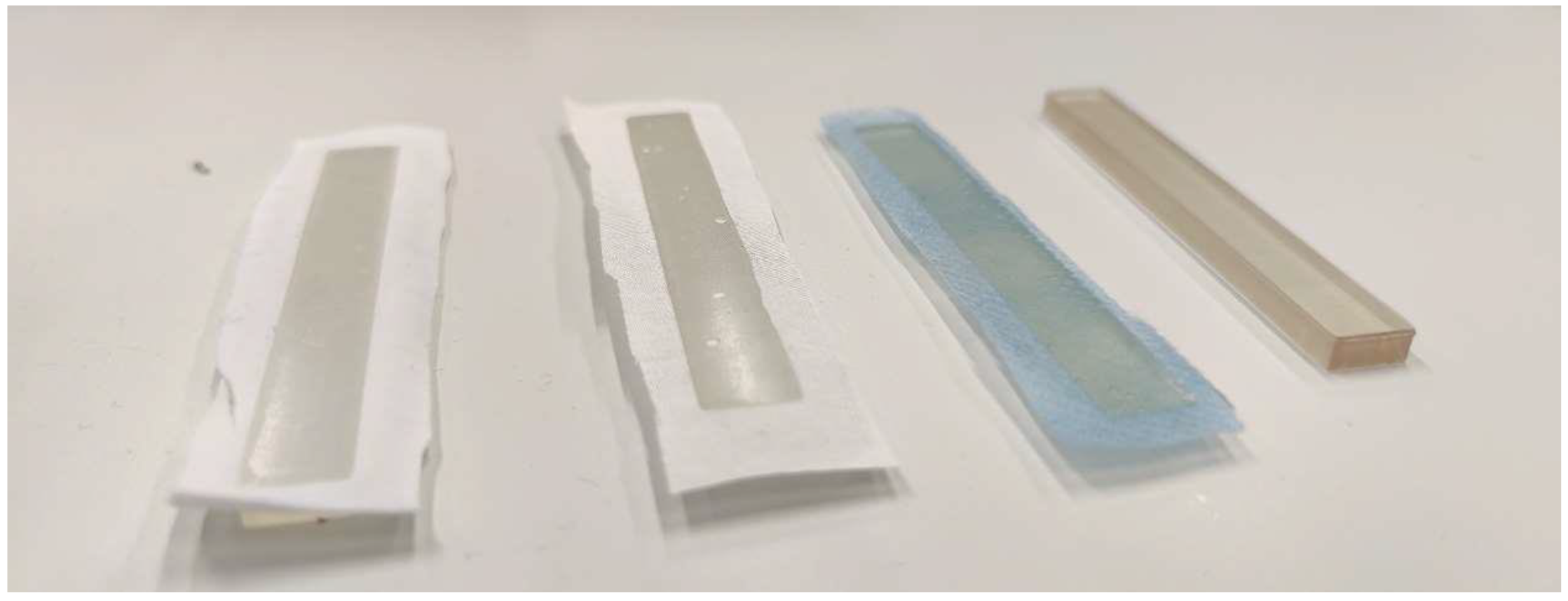
In SLA/DLP printing, it is often useful to place the printed object on the printing bed at a certain angle instead of perfectly flat, as it is common in FDM printing. This avoids large contact areas which may result in too large of adhesion forces between the printed object and the transparent basin’s bottom; as a consequence, this results in deformations to the newly printed layer and thus the object when the printing bed is lifted to let resin flow underneath the part for the next layer. Printing at an angle with support structures is not possible when printing on textile fabrics with the newly constructed sample holder. In order to compare the mechanical properties of pure resin samples with resin/textile composites, it is thus necessary to print all samples directly on the printing bed, with or without a textile fabric fixed to it. Especially for pure resin samples, this led to some of them breaking when they were removed from the printing bed due to their strong adhesion to printing bed. Exemplary results of the backs of these specimens are shown in Figure 2, indicating that the resin penetrated through the fabrics in all cases. More detailed microscopic images of the sample back are depicted in Figure 3. While the resin layer on the back of the printed composites with PET and cotton is nearly completely closed, the structure of the PP nonwoven is partly reproduced in the holes of the resin layer on the back of the sample (Figure 3c). This can be explained by the hydrophobic PP material with pressed diamond-shaped areas, whose borders seem to impede penetration by the resin, resulting in the visible areas here that are not wetted by the resin.
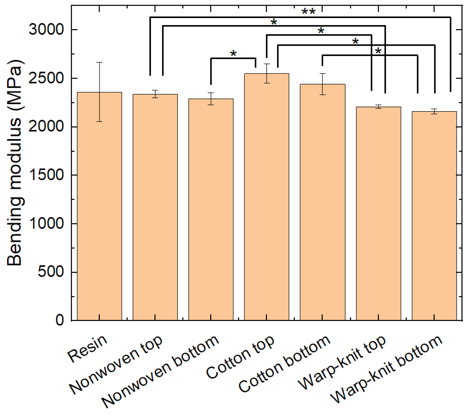
Next, all specimens were subjected to three-point bending tests. Figure 4 shows the bending moduli of the samples. Interestingly, the pure resin samples show a much higher standard deviation than all other samples, which may be attributed to the aforementioned problems of printing them parallel to the printing bed.
On the other hand, the bending moduli of the composites with the elastic warp-knitted fabrics are significantly lower than most other bending moduli, showing that non-elastic textiles increase the bending modulus. This is mostly the case for the thicker and less stretchable cotton fabric, while the thin and slightly stretchable nonwoven fabric has less impact on the bending modulus. This corresponds to the expected influence of embedding a non-elastic layer in a composite outside the neutral fiber in the middle of the sample.
It should also be mentioned that in all cases, the effect of the textile on top is slightly stronger than that of the textile at the bottom. This is unexpected, as during the bending test, the material below the neutral axis is stretched, while the material above the neutral axis—including the textile fabric here—is compressed, and compression of a textile fabric is usually easier than stretching it. A possible explanation is that the composite parts on top of these specimens in which the textile fabrics are fully interfused by resin are less compressible than the pure resin.
In addition to the bending modulus gained from the elastic part of the force–deflection curves, the flexural stress and flexural strain can be examined regarding maximum stress, i.e., the stress where the sample breaks and the respective flexural strains. These values are given in Figure 5. Here again, the pure resin samples show large standard deviations. All samples in which the textile fabrics were at the bottom broke at maximum stress, while deviations between the strain at maximum stress and the strain at break are especially visible for the samples with the PP nonwoven on top. The samples with the PP nonwoven at the bottom, in contrast, showed the lowest stress and strain values compared with the other samples. Generally, samples with a textile at the bottom broke earlier (i.e., at a smaller strain) than samples with the textile on top or the pure resin samples. While this could be expected for the non-elastic textile fabrics, it is less self-evident for the sample with the elastic warp-knitted PP fabric at the bottom. Here, it may be speculated that the composite part of the sample that includes the textile is more brittle due to missing connections of the resin across the yarns.

4. Conclusions

On the one hand, this study aims to construct a new printing bed/sample holder for consumer DLP printers to which textile fabrics can be fixed, showing that most textile fabrics (besides very thick or elastic ones and textile fabrics with very low slippage resistance) can be printed on using this printing bed. On the other hand, it shows the mechanical impact of the textile fabrics on which printing with an SLA resin was performed.
Due to the large amount of available resins for printers based on the photopolymerization of textile materials and structures, the results shown here are naturally not universal for all potential composites. Instead, this study can serve as a starting point to investigate SLA printing on textile fabrics in more detail. The advantages of this technique, based on the low-viscosity resins that can penetrate textile fabrics much easier than the molten polymers used in FDM printing, should be examined further, so that more sophisticated textile/resin composites can be produced to tailor the mechanical properties of technical textiles. Opposite to the previously mostly used FDM printing method on textiles, SLA and other resin-based methods allow for a full penetration of the printed material through the textile fabric if the latter is not too thick. The corresponding composites will thus have other mechanical properties as FDM/textile composites, making them interesting, not only for design purposes due to the high accuracy of SLA printing, but also for technical textiles. Nevertheless, much more research is necessary to fully understand the influence of resins and textile fabrics as well as printing parameters and the potential optimization of the textile holder on the produced composites.

Supplementary Materials

The following supporting information can be downloaded at: https://www.mdpi.com/article/10.3390/textiles4030024/s1: stl files of the final sample holder version as shown in Figure 3a: frame_version4.stl, holder_2_1_2.stl, holder_2_2_2.stls, printing-bed_version4.stl, and spherical-head_version4.stl. The corresponding stp files are available at https://www.mdpi.com/article/10.3390/textiles4030024/s2.

Author Contributions

Conceptualization, J.L.S.; methodology, all authors; validation, J.L.S. and A.E.; formal analysis, P.G.; investigation, D.K. and P.G.; writing—original draft preparation, A.E.; writing—review and editing, all authors; visualization, D.K., P.G., and A.E. All authors have read and agreed to the published version of the manuscript.

Funding

The study was partly funded by the German Federal Ministry for Economic Affairs and Climate Action via the AiF, based on a resolution of the German Bundestag, grant number KK5129708TA1; and partly funded by the German Federal Ministry of Education and Research (BMBF) as part of the “Career@BI” project within the funding program “FH Personal” (03FHP106).

Institutional Review Board Statement

Not applicable.

Informed Consent Statement

Not applicable.

Data Availability Statement

All data are given in the paper or the Supplementary Materials.

Acknowledgments

We would like to thank Ana-Katrina Büttner for language editing.

Conflicts of Interest

The authors declare no conflicts of interest. The funders had no role in the design of the study; in the collection, analyses, or interpretation of data; in the writing of the manuscript; or in the decision to publish the results.

Appendix A

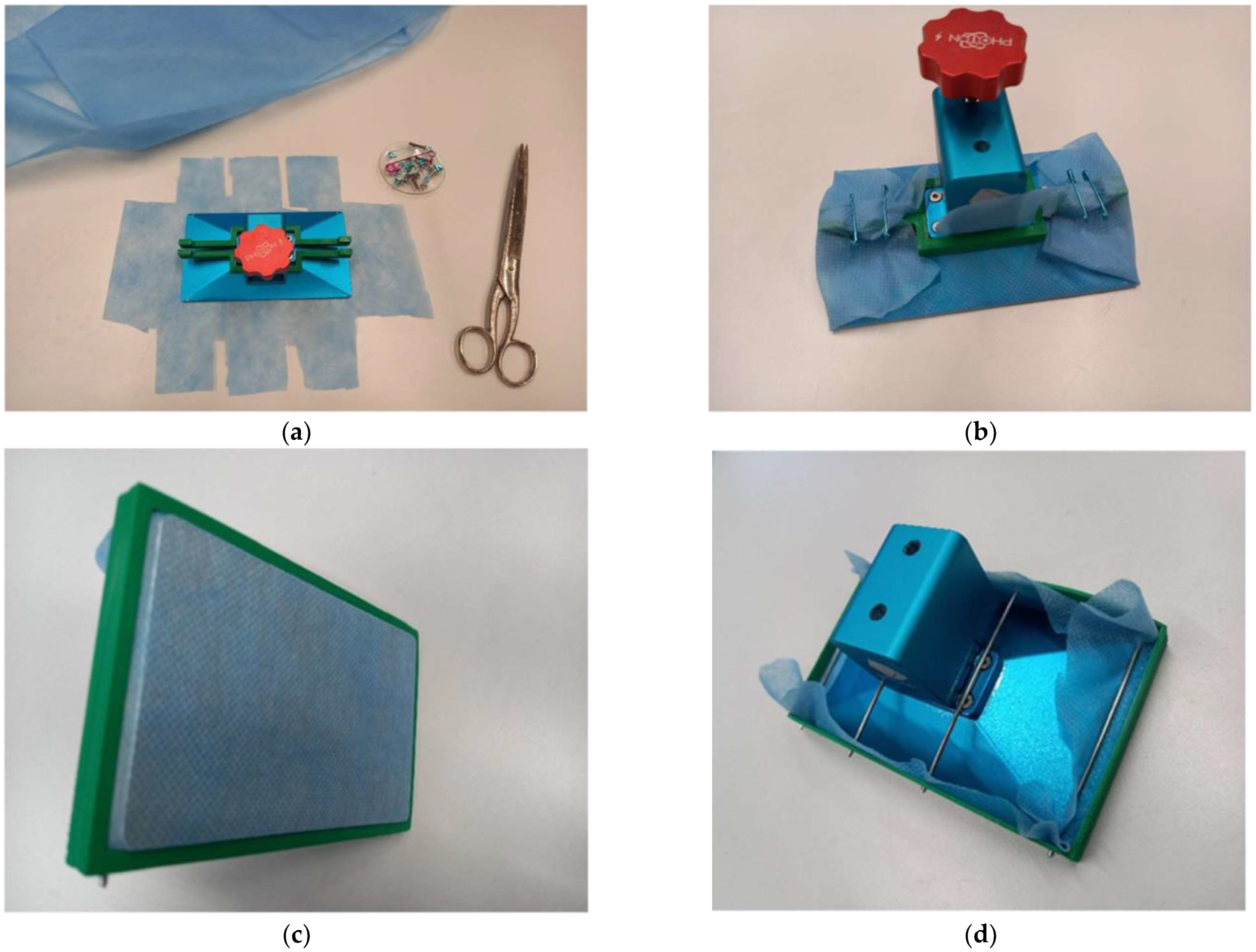
First experiments on different sample holders resulted in solutions that worked but were not easy to handle, such as fixing a textile fabric on the back of the original printing bed with safety pins (Figure A1a,b) or using a frame around the original printing bed and fixing both the textile and the frame with metal pins (Figure A1c,d). Fixation with safety pins was very time-consuming, especially because it was necessary to first cut the textile fabric into the required shape (Figure A1a). In contrast, the frame’s main disadvantage was that the metal pins and also the frame itself could damage the resin basin.
Figure A1. Different approaches for fixing a textile fabric (here, a polypropylene (PP) nonwoven) to the original printing bed of the Anycubic Photon S printer: (a) textile fabric cut before mounting, with green 3D-printed bars for fixation with safety pins; (b) fabric fixed using this bar and safety pins; (c) alternative fixing with a frame, showing the stretched fabric on the printing bed; (d) alternative fixing with a frame, as seen from the back, including metal pins for fixation.
Textiles 04 00024 g0a1
The very first printing bed/sample holder was based on the idea that the printing bed had to be smaller than the original one and be equipped with a frame for fixing the textile. For this, it was necessary to modify the z-axis connection with the printing bed. This new z-axis connector conversely impeded fixing the textile. In addition, the 15 mm height difference between the original (blue) and the custom-made (orange) printing beds (Figure A2a) made leveling (Figure A2b) complicated, so this first approach was considered unsuitable.
Figure A2. First approach for designing a new printing bed/textile sample holder for an SLA/DLP printer: (a) different heights of new (left) and original printing bed (right); (b) new printing bed after leveling.
Textiles 04 00024 g0a2

References

  1. Popescu, D.; Zapciu, A.; Amza, C.; Baciu, F.; Marinescu, R. FDM process parameters influence over the mechanical properties of polymer specimens: A review. Polym. Test. 2018, 69, 157–166. [Google Scholar] [CrossRef]
  2. Oviedo, A.M.; Puente, A.H.; Bernal, C.; Perez, E. Mechanical evaluation of polymeric filaments and their corresponding 3D printed samples. Polym. Test. 2020, 88, 106561. [Google Scholar] [CrossRef]
  3. Zohdi, N.; Yang, R. Material anisotropy in additively manufactured polymers and polymer composites: A review. Polymers 2021, 13, 3368. [Google Scholar] [CrossRef]
  4. Stepashkin, A.A.; Chukowv, D.I.; Senatov, F.S.; Salimon, A.I.; Korsunsky, A.M.; Kaloshkin, S.D. 3D-printed PEEK-carbon fiber (CF) composites: Structure and thermal properties. Compos. Sci. Technol. 2018, 164, 319–326. [Google Scholar] [CrossRef]
  5. Dong, J.; Mei, C.T.; Han, J.Q.; Lee, S.Y.; Wu, Q.L. 3D printed poly(lactic acid) composites with grafted cellulose nanofibers: Effect of nanofiber and post-fabrication annealing treatment on composite flexural properties. Addit. Manuf. 2019, 28, 621–628. [Google Scholar] [CrossRef]
  6. Syrlybayev, D.; Zharylkassyn, B.; Seisekulova, A.; Akhmetov, M.; Perveen, A.; Talamona, D. Optimisation of Strength Properties of FDM Printed Parts—A Critical Review. Polymers 2021, 13, 1587. [Google Scholar] [CrossRef]
  7. Ding, Y.C.; Gracego, A.X.; Wang, Y.R.; Dong, G.Y.; Dunn, M.L.; Yu, K. Embedded 3D printing of UV-curable thermosetting composites with continuous fiber. Mater. Horiz. 2024. online first. [Google Scholar] [CrossRef]
  8. Yao, X.H.; Luan, C.C.; Zhang, D.M.; Lan, L.J.; Fu, J.Z. Evaluation of carbon fiber-embedded 3D printed structures for strengthening and structural-health monitoring. Mater. Des. 2017, 114, 424–432. [Google Scholar] [CrossRef]
  9. Heidari-Rarani, M.; Rafiee-Afarani, M.; Zahedi, A.M. Mechanical characterization of FDM 3D printing of continuous carbon fiber reinforced PLA composites. Compos. Part B Eng. 2019, 175, 107147. [Google Scholar] [CrossRef]
  10. Kocevar, T.N. 3D Printing on Textiles—Overview of Research on Adhesion to Woven Fabrics. Tekstilec 2023, 66, 164–177. [Google Scholar] [CrossRef]
  11. Loh, G.H.; Sotayo, A.; Pei, E.J. Development and testing of material extrusion additive manufactured polymer-textile composites. Fash. Text. 2021, 8, 2. [Google Scholar] [CrossRef]
  12. Cuk, M.; Bizjak, M.; Kocevar, T.N. Influence of Simple and Double-Weave Structures on the Adhesive Properties of 3D Printed Fabrics. Polymers 2022, 14, 755. [Google Scholar] [CrossRef] [PubMed]
  13. Pei, E.J.; Shen, J.S.; Watling, J. Direct 3D printing of polymers onto textiles: Experimental studies and applications. Rapid Prototyp. J. 2015, 21, 556–571. [Google Scholar] [CrossRef]
  14. Sanatgar, R.H.; Campagne, C.; Nierstrasz, V. Investigation of the adhesion properties of direct 3D printing of polymers and nanocomposites on textiles: Effect of FDM printing process parameters. Appl. Surf. Sci. 2017, 403, 551–563. [Google Scholar] [CrossRef]
  15. Grimmelsmann, N.; Kreuziger, M.; Korger, M.; Meissner, H.; Ehrmann, A. Adhesion of 3D printed material on textile substrates. Rapid Prototyp. J. 2018, 24, 166–170. [Google Scholar] [CrossRef]
  16. Demir, M.; Seki, Y. Interfacial adhesion strength between FDM-printed PLA parts and surface-treated cellulosic-woven fabrics. Rapid Prototyp. J. 2023, 29, 1166–1174. [Google Scholar] [CrossRef]
  17. Eutionnat-Diffo, P.A.; Chen, Y.; Guan, J.P.; Cayla, A.; Campagne, C.; Zeng, X.Y.; Nierstraz, V. Stress, strain and deformation of poly-lactic acid filament deposited onto polyethylene terephthalate woven fabric through 3D printing process. Sci. Rep. 2019, 9, 14333. [Google Scholar] [CrossRef]
  18. Goncu-Berk, G.; Karacan, B.; Balkis, I. Embedding 3D printed filaments with knitted textiles: Investigation of bonding parameters. Cloth. Text. Res. J. 2022, 40, 171–186. [Google Scholar] [CrossRef]
  19. Korger, M.; Bergschneider, J.; Lutz, M.; Mahltig, B.; Finsterbusch, K.; Rabe, M. Possible applications of 3D printing technology on textile substrates. IOP Conf. Ser. Mater. Sci. Eng. 2016, 141, 012011. [Google Scholar] [CrossRef]
  20. Mpofu, N.S.; Mwasiagi, J.I.; Nkiwane, L.C.; Githinji, D.N. The use of statistical techniques to study the machine parameters affecting the properties of 3D printed cotton/polylactic acid fabrics. J. Eng. Fibers Fabr. 2020, 15, 1558925020928531. [Google Scholar] [CrossRef]
  21. Korger, M.; Glogowsky, A.; Sanduloff, S.; Steinem, C.; Huysman, S.; Horn, B.; Ernst, M.; Rabe, M. Testing thermoplastic elastomers selected as flexible three-dimensional printing materials for functional garment and technical textile applications. J. Eng. Fibers Fabr. 2020, 15, 1558925020924599. [Google Scholar] [CrossRef]
  22. Alexander, A.E.; Wake, N.; Chepelev, L.; Brantner, P.; Ryan, J.; Wang, K.C. A guideline for 3D printing terminology in biomedical research utilizing ISO/ASTM standards. 3D Print. Med. 2021, 7, 8. [Google Scholar] [CrossRef] [PubMed]
  23. ASTM ISO/ASTM52900-21; Additive Manufacturing—General Principles—Fundamentals and Vocabulary. ASTM International: West Conshohocken, PA, USA, 2021.
  24. Grothe, T.; Brockhagen, B.; Storck, J.L. Three-dimensional printing resin on different textile substrates using stereolithography: A proof of concept. J. Eng. Fibers Fabr. 2020, 15, 1558925020933440. [Google Scholar] [CrossRef]
  25. Chua, C.K.; Leong, K.F.; Lim, C.S. Liquid-based rapid prototyping systems. In Rapid Prototyping: Principles and Applications, 2nd ed.; World Scientific Publishing Company: Singapore, 2003; pp. 35–109. [Google Scholar]
  26. Borrello, J.; Backeris, P. Rapid prototyping technologies. In Rapid Prototyping in Cardiac Disease: 3D Printing the Heart; Farooqi, K.M., Ed.; Springer International Publishing: Basle, Switzerland, 2017; pp. 41–49. [Google Scholar]
  27. Borrello, J.; Nasser, P.; Iatridis, J.C.; Costa, K.D. 3D printing a mechanically-tunable acrylate resin on a commercial DLP-SLA printer. Addit. Manuf. 2018, 23, 374–380. [Google Scholar] [CrossRef] [PubMed]
  28. Kozior, T.; Ehrmann, A. First Proof-of-Principle of PolyJet 3D Printing on Textile Fabrics. Polymers 2023, 15, 3536. [Google Scholar] [CrossRef]
  29. Kozior, T.; Mpofu, N.S.; Fiedler, J.; Ehrmann, A. Influence of Textile Substrates on the Adhesion of PJM-Printed MED610 and Surface Morphology. Tekstilec 2024, 67. online first. [Google Scholar] [CrossRef]
  30. DIN EN ISO 178:2019-08; Plastics—Determination of Flexural Properties (ISO 178:2019). German Version EN ISO 178:2019. ISO: Geneva, Switzerland, 2019. Available online: https://www.dinmedia.de/de/norm/din-en-iso-178/300171601 (accessed on 1 September 2024).
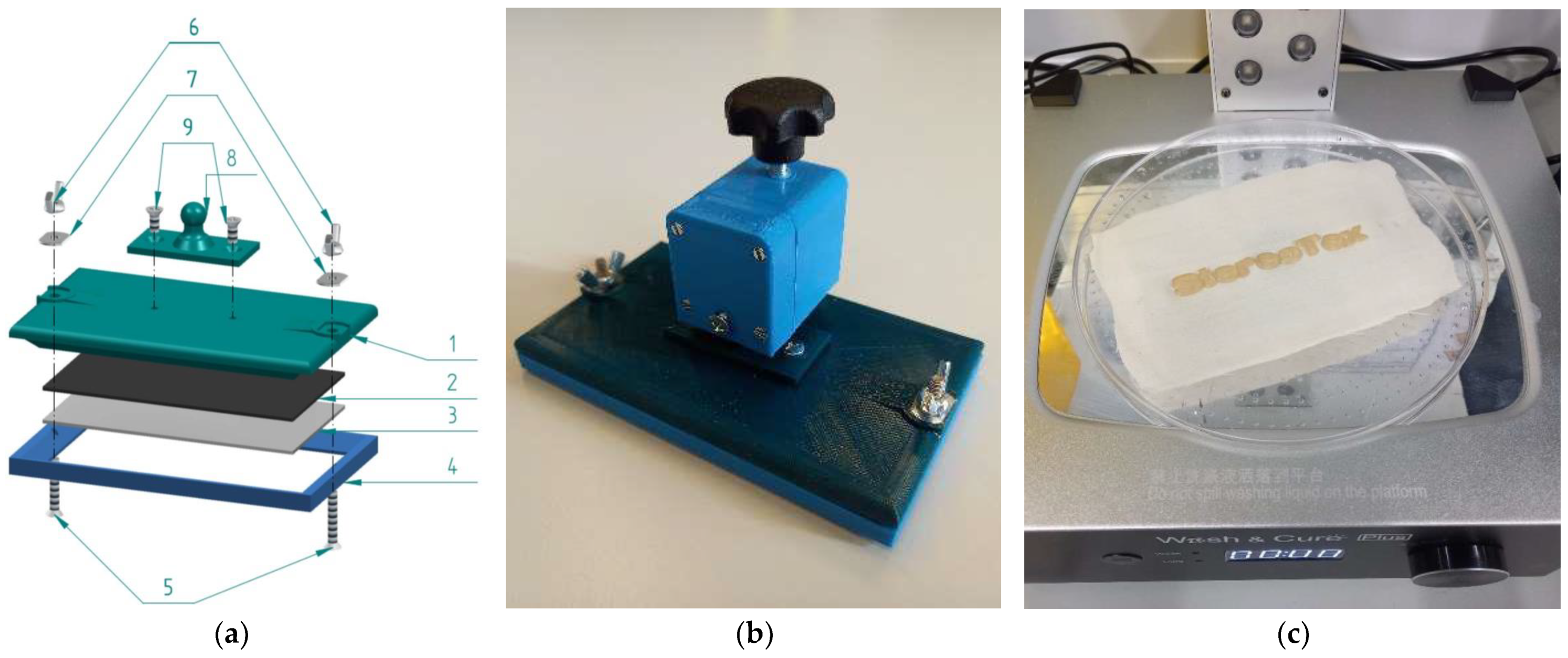
Figure 1. Final printing bed/textile sample holder for a DLP printer: (a) exploded assembly drawing; (b) completely mounted printing bed with z-axis connector; (c) “StereoTex” printed on a textile fabric after washing and curing. The numbers in (a) designate: 1—printing bed; 2—double-sided glue pads 3M 9448A 40 mm × 40 mm; 3—aluminum plate; 4—frame printed from PLA; 5—screws M4 × 25 mm; 6—winged nuts M4; 7—flat washers M4; 8—spherical head holder for z-axis connection; 9—screws M4 × 10 mm.
Textiles 04 00024 g001
Figure 2. From left to right: samples printed on warp-knitted PET, the cotton woven fabric, the PP nonwoven, and the pure resin.
Textiles 04 00024 g002
Figure 3. Microscopic images of the back of the printed composites on different textile fabrics: (a) warp-knitted PET; (b) cotton woven fabric; (c) PP nonwoven. Scale bars correspond to 200 µm.
Textiles 04 00024 g003
Figure 4. Bending moduli of pure resin samples (resins) and samples with textile fabrics on the top or bottom during testing. Error bars show standard deviations. Significant differences are indicated by * (p < 0.05) or ** (p < 0.01), respectively.
Textiles 04 00024 g004
Figure 5. Results of 3-point bending tests: (a) maximum stress and stress at break; (b) strain at maximum stress and strain at break.
Textiles 04 00024 g005
Disclaimer/Publisher’s Note: The statements, opinions and data contained in all publications are solely those of the individual author(s) and contributor(s) and not of MDPI and/or the editor(s). MDPI and/or the editor(s) disclaim responsibility for any injury to people or property resulting from any ideas, methods, instructions or products referred to in the content.