Article

PCM-Impregnated Textile-Reinforced Cementitious Composite for Thermal Energy Storage

by
Túlio Caetano Guimarães
1,
Otavio da Fonseca Martins Gomes
2,3,
Olga Maria Oliveira de Araújo
4,
Ricardo Tadeu Lopes
4,
M´hamed Yassin Rajiv da-Gloria
5,
Romildo Dias Toledo Filho
5,
Eddie Koenders
6,
Antonio Caggiano
7,
Christoph Mankel
6,
Mona Nazari Sam
6,
Rodolfo Giacomim Mendes de Andrade
8 and
Saulo Rocha Ferreira
9,*
1
Postgraduate Program in Biomaterials Engineering, Federal University of Lavras, C.P. 3037, Lavras 37200-900, MG, Brazil
2
Centre for Mineral Technology, Av. Pedro Calmon, 900-Cidade Universitária da Universidade Federal do Rio de Janeiro, Rio de Janeiro 21941-908, RJ, Brazil
3
Postgraduate Program in Geosciences, National Museum, Federal University of Rio de Janeiro, Av. Quinta da Boa Vista, S/N, Bairro Imperial de São Cristóvão, Rio de Janeiro 20940-040, RJ, Brazil
4
Nuclear Engineering Department, COPPE, Universidade Federal do Rio de Janeiro, P.O. Box 68506, Rio de Janeiro 21941-972, RJ, Brazil
5
Civil Engineering Dept., Federal University of Rio de Janeiro, P.O. Box 68506, Rio de Janeiro 21941-972, RJ, Brazil
6
Institute of Construction and Building Materials, Technical University of Darmstadt, L5| 06 207, Franziska-Braun-Straße 3, 64287 Darmstadt, Germany
7
Department of Civil, Chemical and Environmental Engineering, University of Genoa, 5 Via Balbi, 16126 Genoa, Liguria, Italy
8
Civil Engineering and Buildings Department, Instituto Federal do Espírito Santo, Av. Vitória, 1729, Vitória 29040-780, ES, Brazil
9
Civil Engineering Department, Federal University of Lavras, C.P. 3037, Lavras 37200-900, MG, Brazil
*
Author to whom correspondence should be addressed.
Textiles 2023, 3(1), 98-114; https://doi.org/10.3390/textiles3010008
Submission received: 24 November 2022 / Revised: 1 February 2023 / Accepted: 2 February 2023 / Published: 9 February 2023
(This article belongs to the Special Issue Fibrous Materials (Textiles) for Functional Applications II)

Abstract

:
The growing global energy demand requires solutions that improve energy efficiency in all sectors. The civil construction sector is responsible for a large part of global energy consumption. In this context, phase change materials (PCMs) can be incorporated into construction materials to improve the energy efficiency of buildings. The purpose of this study was to incorporate a PCM to jute fabric, applying it in civil construction as a reinforcement for cement matrices. In order to do that, a method of immersing jute fabric in liquid phase change material, and then coating it with a polymer, was proposed. Treated jute fabric was then used to produce a laminated composite with a cementitious matrix. Morphological, mechanical and chemical characterization of jute textiles was performed, as well as an analysis of the composites’ mechanical and thermal behavior. The results verified that jute textiles absorbed 102% PCM in weight, which was successfully contained in the capillary porosity of jute. The PCM was able to delay the composite’s temperature increase by up to 24 °C. It was concluded that this method can be used to incorporate PCM to natural textiles, producing composites with thermal energy storage properties.

1. Introduction

Solutions related to the improvement of energy efficiency offer some of the fastest and most cost-effective actions to reduce CO2 emissions [1]. Storage technologies, such as thermal energy storage (TES), are a central component of energy-efficient and sustainable energy systems. Phase Change Materials (PCMs) are a promising option for passive thermal energy storage systems, due to their property of storing large amounts of energy in the form of latent heat [2]. When incorporating PCM into construction materials, it significantly contributes to sustainable construction, as it allows an enhanced thermal regulation, reducing the consumption of non-renewable energy sources [3].
Focusing on the thermal performance of buildings, which consequently helps to reduce energy consumption and GHG emission, in the last few years researchers have developed relevant works on PCM-incorporated construction materials, such as recycled materials with PCM [4,5], Bio-PCMs [6,7,8], cement-based systems with microencapsulated PCMs [9,10,11], PCM walls [12,13], PCM incorporated into lightweight aggregates [14], wood flooring with microencapsulated PCM [15], and delignified wood composite phase change materials [16], amongst others.
Despite their potential for application in thermal energy storage systems, PCMs present some challenges that limit their use, such as low thermal conductivity [17], supercooling [18], and leakage (when PCM is directly incorporated into the material) [19]. In order to prevent PCM leakage, shape stabilization methods can be applied, consisting of employing a support matrix, such as polymers, porous materials, or nanomaterials [20,21,22] to contain the PCM. Numerous porous materials have been investigated as containers for PCM, including expanded graphite [23], diatomite [24], expanded vermiculite and perlite [25], kaolinite [26], pumice [27], hydroxyapatite [28], cellulose, agarose and chitosan [29], and cellulose aerogel [30]. However, these works have not yet utilized natural raw materials as containers for PCM and have not yet incorporated PCM into reinforcements for concrete.
Due to their morphological characteristics, plant fibers are naturally porous. Hemp, sisal, and jute fibers find their porosity to be 2.46, 10.85, 11.36, and 73.95%, respectively [31], which makes them potentially suitable containers for PCMs. Additionally, plant fibers used as reinforcement for cement-based matrices have demonstrated that polymeric coating treatments can reduce water absorption and are effective in the sealing process of the fibers [32,33,34]. Previous studies [35,36] have developed a textile-reinforced concrete utilizing polymer-coated jute fabric as reinforcement. The treatment of jute fabric with carboxylated styrene–butadiene rubber (XSBR) increased the tensile strength and strain capacity of the composites.
This work proposed a novel method of utilizing the sealing of the fibers provided by polymeric coating as a way to also contain the PCM, preventing its leakage. Jute fabric was immersed in liquid PCM, absorbing it by capillarity, and then it was coated with XSBR. Coated fabric was then used as a reinforcement for laminated composites. Bending tests were performed in order to evaluate the mechanical performance of these composites, as well as heating and cooling cycles in thermally insulated chambers to evaluate their thermal behavior.

2. Materials and Methods

2.1. Materials

Jute fibers originate from the stem of the Corchorus capsularis plant, through a process of cutting, retting, shredding, drying, packing, and sorting [37], while their textiles are produced via spinning and weaving processes. Acquired from the company Companhia Têxtil Castanhal (São Paulo-SP, Brazil), the textile used in this work has a mesh opening of 3 yarns/cm in the transverse direction and 3.5 yarns/cm in the longitudinal direction, as depicted in Figure 1.
A bio-based organic PCM with a phase change temperature of approximately 24 °C was selected for this work (CrodaTherm 24-LQ-(GD), from Croda do Brasil Ltda, Campinas, SP, Brazil), with a phase change temperature of approximately 24 °C. The physical properties of this PCM are found in Table 1. A carboxylated styrene–butadiene rubber, XSBR NTL-218, with a medium styrene content, manufactured by Nitriflex (Duque de Caixas-RJ, Brazil) was chosen as the polymer used for coating the natural fibers.
Finally, the following materials comprise the cementitious matrix mix constituents: Portland cement CP II F32 (equivalent to the European CEM II [38], manufactured by CSN company at Serra, ES, Brazil); metakaolinite (manufactured by Metacaulim do Brasil, at Jundiaí, SP, Brazil); river sand passing through a 1.19-mm sieve; fly ash; BASF’s MasterGlenium 51 superplasticizer (PA type) with a solids content of 51%.

2.2. Methods

2.2.1. Scanning Electron Microscopy

Untreated and treated jute yarns were investigated with a FEI Quanta 400 scanning electron microscope (SEM). The specimens were sputter coated with a thin layer of about 20 nm of silver using a BAL-TEC SCD 005 sputter coater. This process is necessary to provide conductivity to the specimens of non-conductive materials, such as these natural fibers. This improves the quality of the SEM images and analysis. It is worth mentioning that silver was used, instead of the more commonly used gold, because it costs much less, and it can provide good quality SEM images in a low magnification [39]. The microscope was operated under 20 kV of acceleration voltage, in a high vacuum mode. The images were acquired using a back-scattered electrons detector.

2.2.2. Micro-Computed Tomography (Micro-CT) Scans

Micro-CT scan images of untreated and treated jute yarns embedded in cement matrices (w/c ratio = 1:0.3) were obtained in order to analyze the effect of the polymer coating treatment on the interface of the system. For the image acquisition, single yarns were placed inside 2 mL microcentrifuge tubes, and then filled with the cement paste.
For the micro-CT acquisition, a V/TOMEX/M (GE Measurement & Control Solutions, Wunstorf, Germany) was used. The micro-CT parameters for the acquisition included a voltage of 70 kV, an energy of 280 μ A , 5 frames, and an Al filter with a thickness of 0.5 mm. The geometry had a magnification of 9.37, pixel size of 21 μ m , and a total of 1200 projections.

2.2.3. Immersion of Jute Fabric in Liquid PCM and Polymer Solution

Immersion is reported as a suitable method for incorporating PCM into porous materials, such as lightweight aggregates [3,14]. Due to jute fibers’ natural porosity (11%) [31], the immersion method can be used to incorporate PCM into jute fabric.
The jute fabric was immersed in liquid PCM . Depending on weather conditions, the PCM was in a liquid state at room temperature (t ≥ 24 °C.). However, it was melted and kept in a kiln at 60 °C until the immersion procedure when necessary. PCM was impregnated into the fibers’ pores by capillary absorption, as depicted in Figure 2a; excess liquid was then removed in tray 2 (Figure 2b). Since the leakage effects of liquid PCM inside the open capillary pores of jute fibers can occur during a phase change, a maximum degree of saturation of 80% volume was applied [4]. Thus, a 2-min immersion time was recommended to obtain that degree of saturation of PCM in jute fabric.
Jute textiles were then treated by total immersion in an XSBR polymer bath at room temperature for 50 min , as shown in Figure 2c, followed by drying in open air for 72 h, in accordance with Fidelis et al. [33]. In addition, the influence of a multilayered coating was evaluated in 3 cm × 3 cm fabric specimens. In a 3-time process, after a coating layer, the fabric mass was measured, as well as its thickness. Finally, the non-occurrence of liquid PCM leakage was verified: by mass loss (during 14-day mass measurement) and by the difference between densities (after 3-day water immersion).
Along with this procedure, the fabric’s capacity for PCM absorption was determined by Equation (1):
A ( % ) = m t m 0 m 0 × 100 % ,
where A is the absorption, represented by the mass gain, and mt is the specimen mass at time t and m0 is the initial mass; 3 × 3 cm untreated specimens were tested.

2.2.4. Mechanical Characterization of Jute Fibers

Under a controlled temperature of 18 °C, direct tensile tests were performed on an AROTEC WDW-20E universal testing machine (Arotec Indústria e Comércio company from Cotia-SP, Brazil), in accordance with ASTM C1557 [40]. Measured with a 5 kN load cell, with a constant displacement rate of 1.25 mm/min, 250 mm long yarn samples and 60 × 250 mm (width × length) samples were selected (Figure 3a). In order to avoid specimens’ slippage during the test, rubber sheets were glued to each end (Figure 3b).
The tensile strength of the yarns was determined by dividing the maximum force measured in these tests by the average cross-sectional area (0.48 mm 2 ), as measured by Fidelis [35]. The area of the fabric was determined based on the average number of yarns in the specimens of these dimensions.

2.2.5. Chemical Characterization of Jute Fibers

Fourier-transform infrared spectroscopy (FTIR) and thermogravimetry analysis (TGA) were carried out in order to evaluate the interaction of the jute fibers with the proposed components, i.e., PCM and XSBR; the following jute samples were used: in natura, coated with XSBR polymer, impregnated with PCM, and coated with XSBR polymer (Figure 3c).
For the FTIR analysis, the attenuated total reflectance (ATR) sampling method was used. The spectral range analyzed was from 4000 to 675 cm−1, with 24 scans and a resolution of 4 cm−1. For the thermogravimetry analysis, the samples were initially submitted to a constant temperature of 40 °C for 30 min in order to remove the free water present in the material. Then, the samples were heated from 40 to 1000 °C at a constant heating rate of 10 °C/min, under an N2 atmosphere. Both tests were based on the method proposed by Ferreira et al. [34].

2.2.6. Composite Production

Laminated composites containing three layers of jute fabric were produced. As depicted in Figure 4, the composite comprises of seven layers, alternating between mortar and jute fabric, totalling 15 mm thick.
A ratio of 1:0.5:0.4 (binding:sand:water/cement ratios (% weight)) was adopted for the mortar, with 1.5% of superplasticizer [41]; the mix proportions of the mortar can be observed in Table 2. For the mortar reinforcement, in natura jute fabrics (2-hour hot water washing and 24-hour drying at 60 °C [42]), as well as XSBR-coated jute fabrics (with and without impregnated PCM), were used. The mortar was produced as follows: mixing of the dry materials; gradual addition of water; addition of superplasticizer; mixing until the matrix was homogenized.
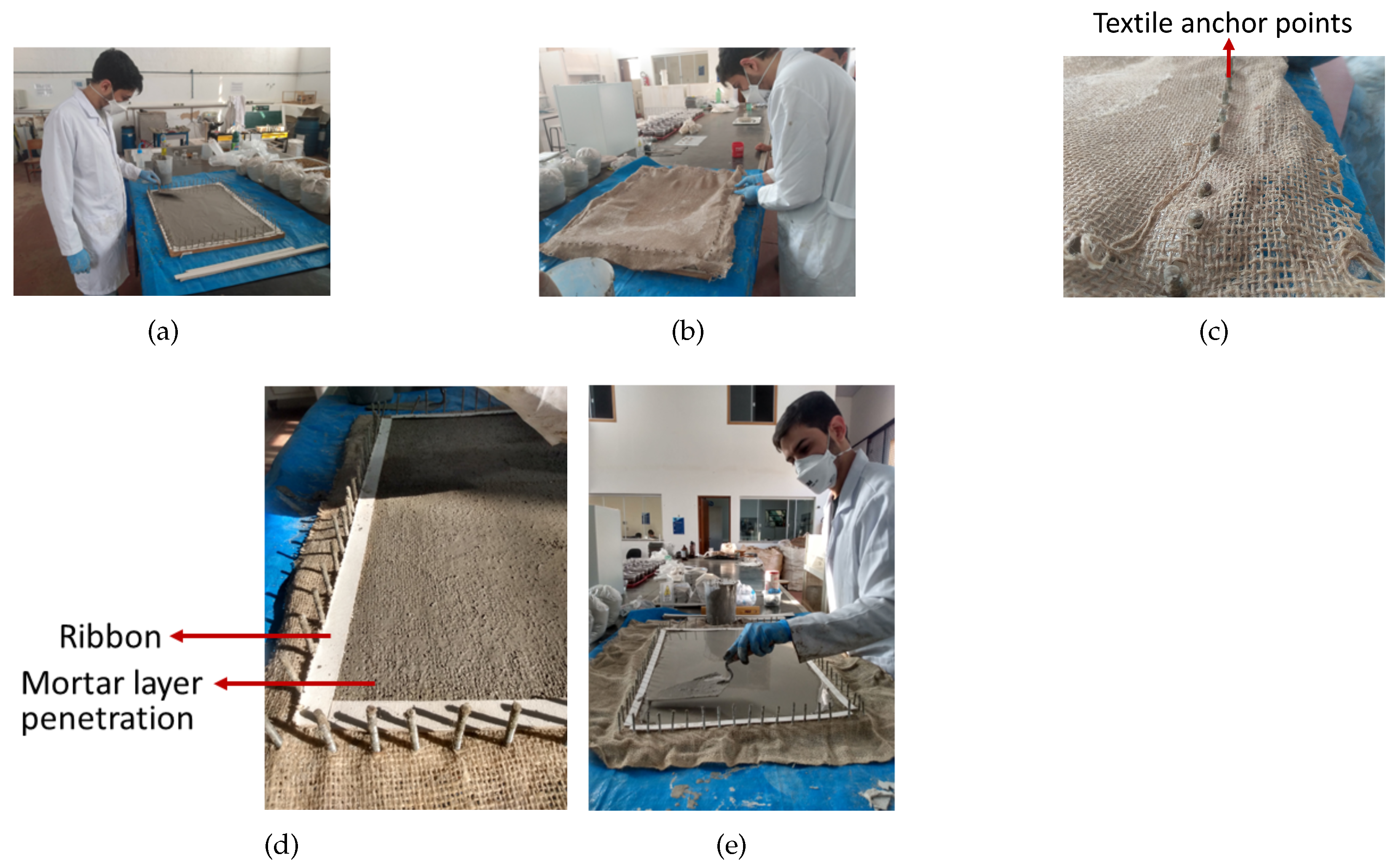
The molding process [35] is illustrated in Figure 5. On a 485 × 650 mm mold, paper ribbons delimited the casting area (Figure 5a). After the first mortar layer was applied, the jute fabric was anchored and stretched on the threaded studs (Figure 5b,d) up to the last (and fourth) mortar layer (Figure 5e). The plates were then placed in a curing chamber for 28 days, after which they were sawed into four 75 × 325 mm specimens for the mechanical tests, and one 170 mm × 240 mm specimen for the thermal test, as illustrated in Figure 6a.

2.2.7. Mechanical Characterization of the Laminated Composites

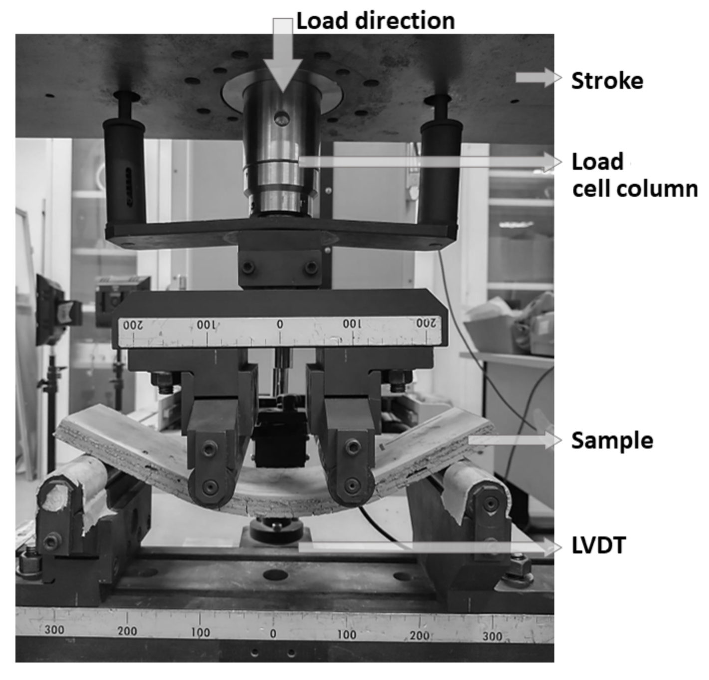
RILEM’s four-point flexural tests were carried out to evaluate the mechanical behavior of the composites [43]. In a Shimadzu universal testing machine (Shimadzu Corporation, Kyoto, Japan), at a room temperature of 23 °C, the tests were performed under a displacement rate of 0.3 mm/min, and measured with a load cell of 100 kN. The span length between supports was 270 mm, and the distance between loading pins was 90 mm.

2.2.8. Thermal Behavior of Composites

The thermal behavior of the composites was evaluated through heating and cooling cycles of two thermally insulated chambers, simulating outdoor conditions. A 15 W incandescent light bulb was used as a heat source and eight thermocouples were used to register the evolution of the temperature in four different regions: one in each chamber (air temperature), one on the lower face of the specimen, and one on the upper face . The setup is illustrated in Figure 6b.
The specimens were initially kept at a temperature lower than the PCM’s phase change temperature (19 °C). After the system reached a steady state, the heat source was turned on, recording the temperature every 5 s for 90 min. The test time was determined to be sufficient to observe the temperature range in which the PCM’s phase change occurs. After this period, the heat source was turned off and the upper chamber was removed, releasing the hot air, and replaced with another chamber, containing glasses with ice, to cool the environment for another 90 min. Specimens from plates produced with jute containing PCM, as well as the reference material not containing PCM, were tested.

3. Results and Discussion

3.1. SEM and Micro-CT Scan Image Analysis

Figure 7 shows the cross-section images of jute yarns in the following conditions: in natura (Figure 7a), XSBR-coated (Figure 7b), and PCM-impregnated and XSBR-coated (Figure 7c). The red arrows in Figure 7b and c indicate the fibers in coated specimens. Jute yarns presented an area ranging between 0.48 and 0.55 mm 2 , while the outer area of treated yarns, i.e., taking the coating into account, presented an average value of 1.38 mm 2 . It is noteworthy to state that the magnitude of the diameters is in accordance with Fidelis et al. [33].
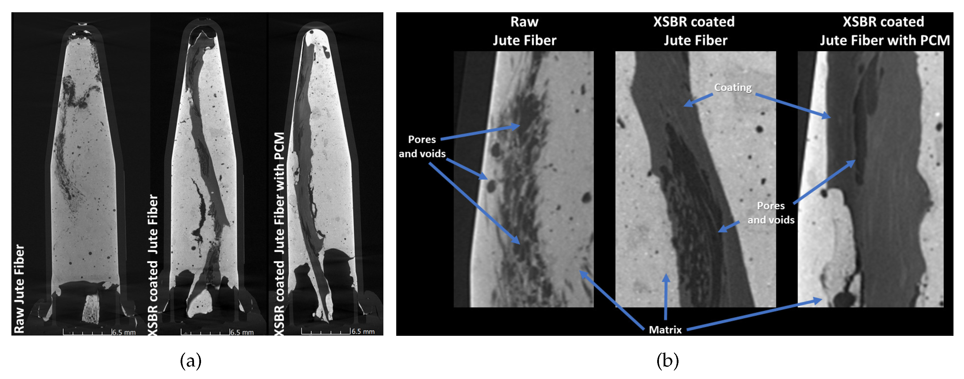
Micro-CT scan images of longitudinal sections of single jute yarns embedded in cementitious matrices are presented in Figure 8a. As observed in Figure 8b, the presence of voids on the interface region between the in natura jute yarn and the matrix occurs due to the poor interaction between them, whereas a more cohesive interface can be observed between XSBR-coated jute yarns and the matrix. Due to the polymer’s interaction with both the fiber and matrix, a stronger adhesion was observed. In addition, the polymer completely coated the fibers, preventing the PCM from leaking .

3.2. Jute Fabric PCM Absorption and Polymer Coating Treatment

Two methods were adopted to evaluate the sealing effectiveness of the polymer coating on the jute fabrics: (I) visual, which verified the absence of liquid PCM leakage after the fabric treatment process was considered as fully dried, and (II) direct measurement, which assessed the fabric’s thickness and mass after each treatment process. Both methods’ results can be observed in Figure 9.
PCM leakage was detected, as some droplets were observed in water after immersion of in natura fabric (Figure 9a). On the other hand, no droplets were observed after the immersion of the polymer-coated fabric (Figure 9b), thus being a good indicator of the polymer’s sealing effectiveness.
Jute fabric specimens’ PCM absorption after immersion in liquid PCM was, on average, 102% of the fabric’s mass, which can be observed in Figure 9c. After a single bath for 50 min, the layer of XSBR formed measured, on average, 71.6% of the yarn’s diameter. The mass gain was the most expressive at this step, at 276.7% of the untreated fabric’s mass. This is probably due to the penetration of the polymer between the fibers, filling voids, as observed in the SEM images discussion. After three drying and immersion cycles, the average thickness of the polymer layer reached 177.0% of the yarn’s diameter.
Figure 9d shows a 14-day evolution of specimens’ mass loss after polymer coating, under laboratory conditions. During the first 3 to 7 days, the mass loss occurs due to the polymer drying, while on the subsequent days, no variations greater than 1% were observed, indicating that no PCM leakage was occurring.
Due to XSBR’s low thermal conductivity (0.092 W/m.K) [44], the formation of a thick layer of polymer over the fabric’s fibers can hinder heat exchange, which can reduce the action of the PCM. Since no PCM leakage was observed after treatment with a single immersion, no additional immersions were necessary in subsequent treatments.

3.3. Mechanical Characterization of Jute Fibers

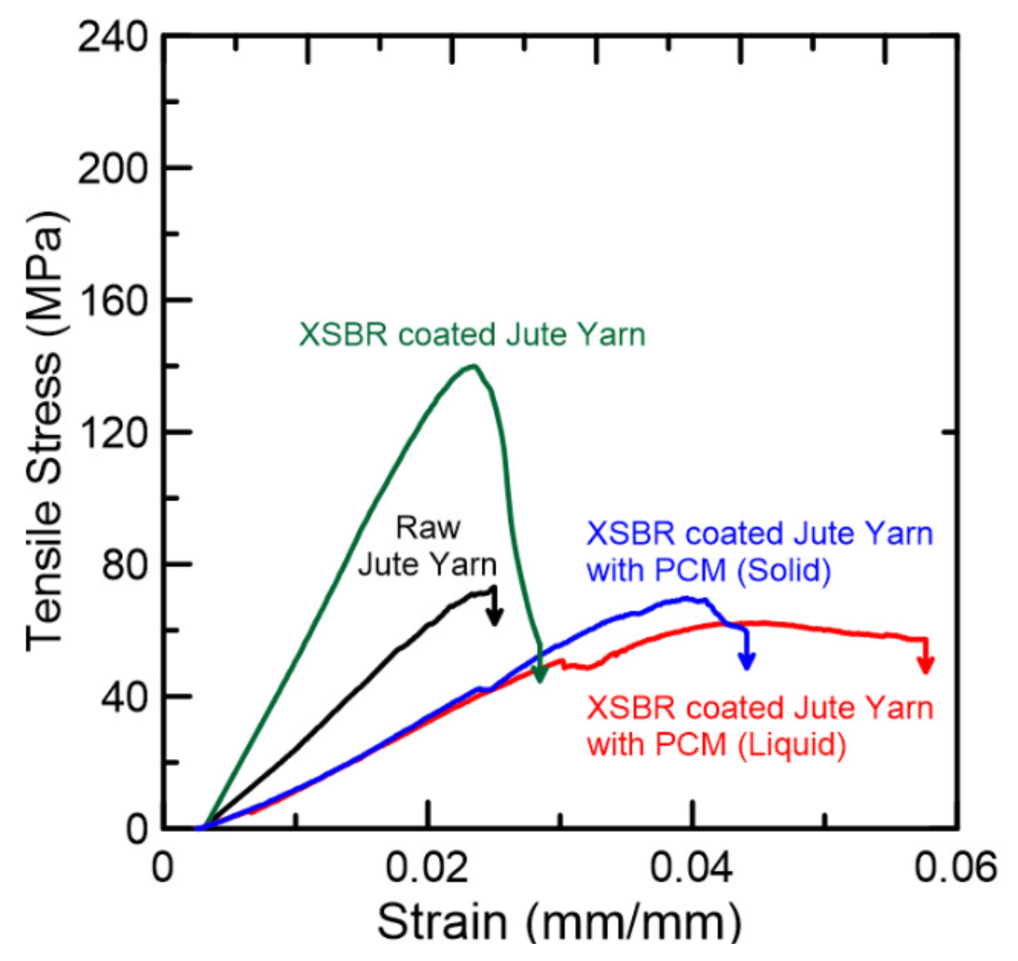
Tensile strength tests were performed on yarn and fabric specimens in the following conditions: in natura, XSBR-coated, and PCM-immersed plus XSBR-coated. Due to the mesh opening, the fabric was tested in the transverse and longitudinal directions. Thus, Figure 10 illustrates typical stress–strain curves of the reinforcements’ behavior, while Table 3 shows the average results of the tensile strength and elastic modulus; similar values for untreated yarns and jute fabric were found by Fidelis et al. [35].
The presence of PCM in a either solid or liquid state caused a reduction of approximately 40–50% of the jute’s tensile strength when compared to yarns without this material. In addition, there was no difference in behavior due to the PCM state during the linear ascending branch. However, after reaching the limit of proportionality, the physical state of the PCM influenced the tensile behavior: jute yarns containing solid PCM kept their original slope up to their rupture, while jute yarns containing liquid PCM presented a plateau, with a strain 40% larger than the former.

3.4. FTIR

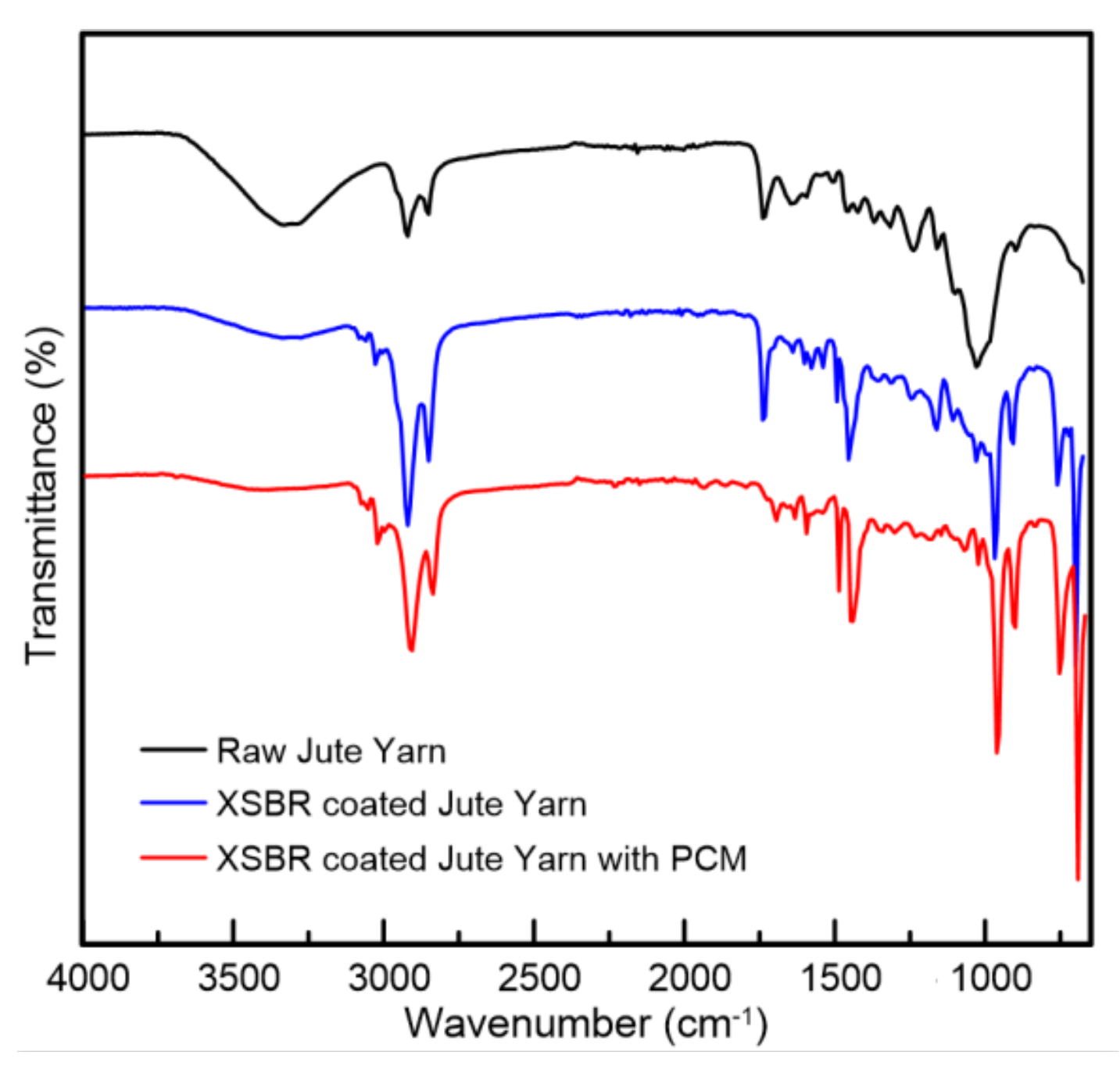
The results of the FTIR analysis were obtained through the transmittance as a function of the wave number, as depicted in Figure 11. For the untreated jute fibers, a broad peak between 3700 and 3100 cm−1 was observed, relative to the stretching of O–H bonds of carboxylic acid and alcohol functional groups and water absorbed by the material. This peak tends to decrease in intensity or disappear almost completely in treated samples, due to the sealing of the fiber by the polymer, preventing the entry of water and the lower content of the jute in the treated samples.
Between 3100 and 3000 cm−1, low intensity peaks are observed in the treated samples, related to the stretching of =C–H bonds in alkenes, present in the polymers due to the butadiene monomer. A more intense peak in this region at about 3030 cm−1 refers to the stretching of C–H bonds in aromatic rings, due to the presence of styrene.
Two peaks can be observed at 2919 and 2850 cm−1, related to the stretching of C–H bonds in alkanes. These bonds are present in the components of the jute fibers (cellulose, hemicellulose, and lignin) and the soluble extractives, but the bonds are also present in the structure of the polymers used, resulting in an increase in the intensity of these peaks in treated samples.
A peak can also be observed at 1735 cm−1, relative to the stretching of C=O bonds. This peak is attributed to the acetyl and uronic ester groups of hemicelluloses or to the ester bond of the carboxylic groups of ferulic and p-coumaric acids of lignin and/or hemicellulose [45]. Furthermore, an increase in the intensity of these peaks is observed in samples treated without PCM, due to the C=O bonds of the carboxyl groups of the polymers. However, in samples containing PCM, these peaks tend to decrease in intensity and to be displaced slightly, possibly due to interactions between the PCM and C=O groups present in XSBR and jute components.
In the region between 1500 and 1400 cm−1, the occurrence of several peaks can be observed. At 1492 cm−1, it is observed that the samples treated with XSBR present a more intense peak, related to the C=C bonds of aromatic rings. At 1450 cm−1, peaks related to the deformation of the C–H bond of alkanes are found in all samples, but are more intense in those treated with polymer, as well as the peaks at 2919 and 2850 cm−1. Finally, it is also possible to identify the occurrence of peaks between 1440 and 1395 cm−1, due to the deformation of the –OH bond in carboxylic acids.
It is observed, in the region between 1300 and 1000 cm−1, the occurrence of some peaks related to the stretching of C–O bonds, characteristic of alcohol, carboxylic acids, ester, or ether functional groups, present in components of the jute fibers or the polymer. In the region between 1220 and 1133 cm−1, there was a decrease in the peak intensity in samples containing PCM, presumably related to interactions between PCM and jute components or XSBR.
Finally, in the region between 1000 and 675 cm−1, peaks related to the deformation of C–H bonds in mono-, di-, or tri-substituted carbons or C=C bonds are observed. The presence of sharp peaks at 966 and 910 cm−1 in treated samples is mainly due to the C=C bonds of the butadiene monomer, present in XSBR. Furthermore, the peaks at 760 and 698 cm−1 are relative to a mono-substituted benzene derivative, which is identified as the styrene monomer of the XSBR co-polymer.

3.5. Thermogravimetric Analysis

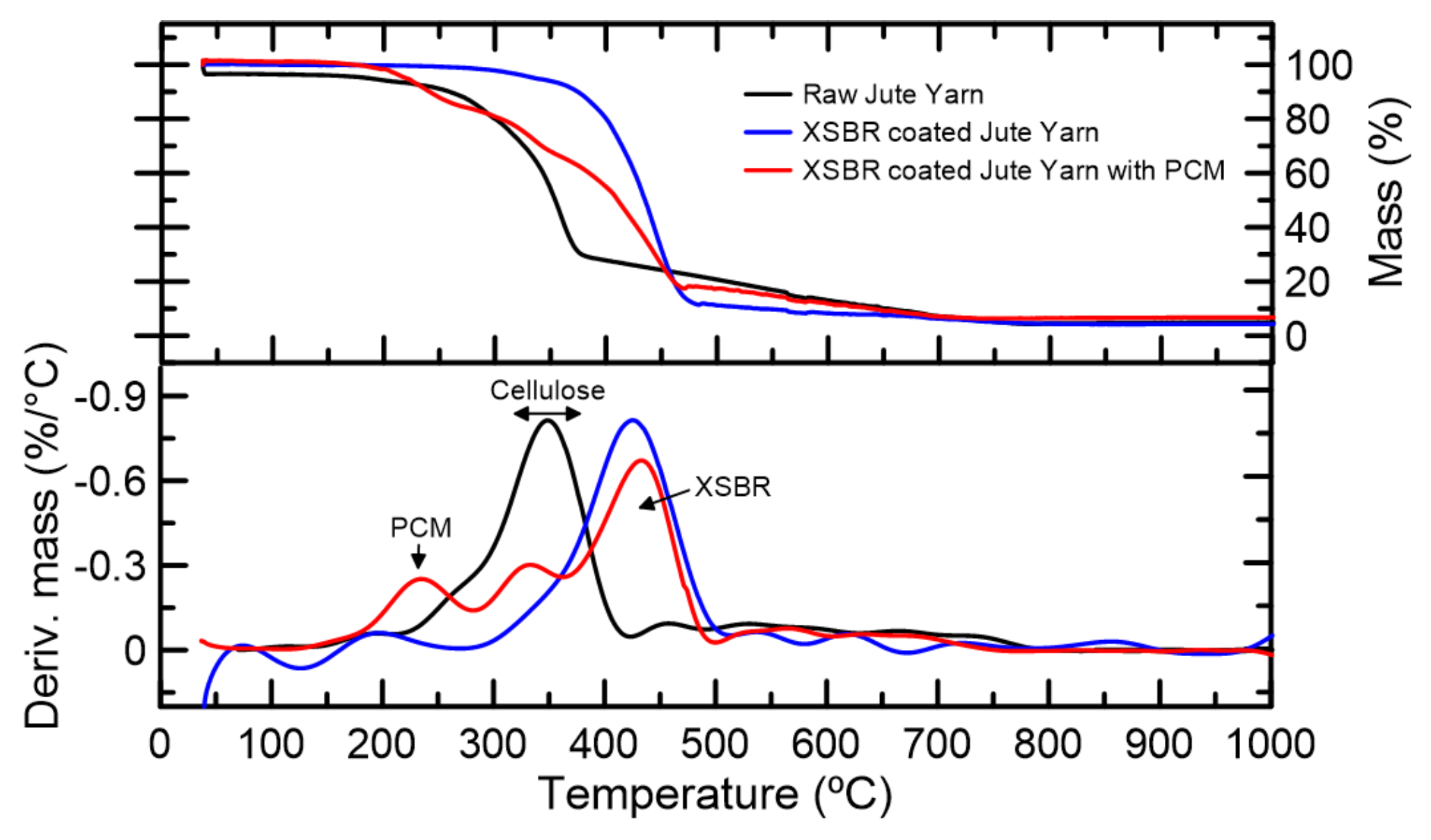
In Figure 12, thermogravimetry (TG) and differential thermogravimetry (DTG) curves are shown. It can be observed that initially, there is a loss of about 3.8% in the mass of raw jute yarn, due to the release of free water present in the material during the first 30 min, in which the temperature was maintained at 40 °C. Three other mass loss events were also observed when analyzing this curve. The initial shoulder, occurring around 250 and 320 °C, corresponds to the degradation of hemicellulose, which occurs between about 150 and 350 °C [46]. Then, a sharp peak is observed with a center at 348 °C, corresponding to the degradation of cellulose. The temperature of this peak is close to that observed by Poletto et al. (2014) for jute fibers, which was 365 °C [47]. Finally, a broad peak of lower intensity can be observed with a center at about 458 °C, which corresponds to the degradation of lignin, and typically occurs at about 250 to 600 °C.
The loss of mass observed in the curve of raw jute due to the free water present in the material was not observed in the other curves, since treatments with polymers provided a sealing of the fibers, reducing water absorption [34], which was confirmed by lower intensities of the bands between 3700 and 3100 cm−1 observed in FTIR spectra, as discussed in Section 3.4. Thermal stability, evaluated by the temperature at which a 3% mass loss occurs, was lower for the specimen that contained PCM in relation to treated specimens without PCM. These results can be observed in Table 4. This is due to the fact that the degradation of the PCM, an organic ester, starts at relatively low temperatures [47]. As opposed to the specimens that did not contain PCM, a DTG peak with a center around 234 °C was observed on the curve of the specimens containing PCM, corresponding to its degradation. These results, combined with the results from the previous section, confirm the presence of the PCM in the samples and the effectiveness of the proposed method to incorporate the PCM to jute textiles.
The polymer coating provided greater thermal stability, with an increase of about 100 °C in the temperature at which a 3% mass loss was reached in relation to the untreated jute. It was also observed that the use of treatments shifted the main DTG peak from 367 to about 447–452 °C, a temperature range corresponding to the pyrolysis of XSBR [48], due to its higher content in the samples.

3.6. Mechanical Behavior of Composites

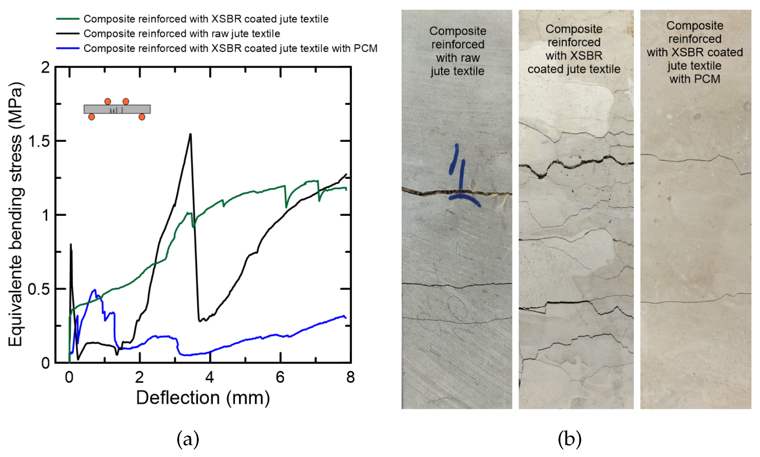
The setup of the flexural test is illustrated in Figure 13, in which the tests were carried out on the following specimens: in natura textile-reinforced composites (T1), XSBR-coated textile-reinforced composites (T2), and PCM-impregnated XSBR-coated textile-reinforced composites (T3). Typical curves of the four-point flexural are shown in Figure 14a. It can be observed that the composites present a linear behavior until the occurrence of the first crack. In all cases, the textile reinforcement presented a large displacement, which indicated a considerable increase in ductility when compared to a cementitious matrix. The maximum equivalent flexural stress was, on average, 0.96, 1.94, and 1.03 MPa for T1, T2, and T3, respectively.
In Figure 14b, photographs of cracked specimens after bending tests can be observed. T1 composites presented two to three cracks, while T2 presented multiple cracks, indicating a deflection-hardening behavior. Finally, T3 composites presented two cracks, which could be related to the yarn’s strength (see Section 3.3). The formation of these cracks can be identified in the curves by the abrupt decrease in flexural stress, followed by its subtle increase.
The improvement of the mechanical behavior observed in the composites with the XSBR-coated jute fabric can be justified by a better interface between the jute textile and cement-based matrix. As indicated by [33,34], carboxylated styrene–butadiene rubber can chemically interact with calcium-based products produced during cement hydration. This improved interface can also be observed in micro-CT scan images, as discussed in Section 3.1. This enhanced adhesion between the fibers and the matrix helps promote an enhanced stress transfer to adjacent areas after a crack opens, inducing multiple cracks. During all tests, no layer delamination was observed.

3.7. Thermal Behavior of Composites

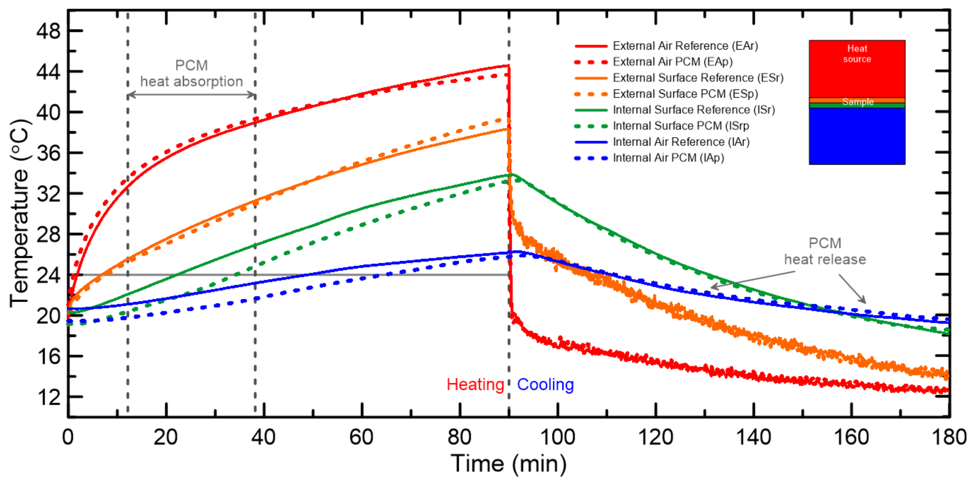
The results of the tests can be observed in Figure 15. Solid lines represent the reference material (without PCM), while dashed lines represent the material with PCM. Each color represents an average measurement of a pair of thermocouples, simultaneously positioned in different regions, as follows: upper chamber air (simulating the external air), the upper surface of the specimen, the lower surface of the specimen, and the lower chamber air (simulating the internal air).
When the PCM-impregnated and XSBR-coated textile-reinforced plate reaches 20–24 °C, the PCM begins to change its phase, absorbing heat and hence delaying the temperature increase. While the lower surface of the reference material takes about 25.5 min to reach 24 °C, the PCM-impregnated plate takes 34% longer, i.e., 34.3 min to reach the same temperature. This result demonstrates the effectiveness of the jute textile reinforcement containing PCM for thermal energy storage.

4. Conclusions

The proposed method of incorporating and containing a PCM within the pores of jute textiles through immersion in liquid PCM, followed by a polymer coating treatment using a styrene–butadiene carboxylated rubber (XSBR), succeeded. PCM absorption by jute textiles was, on average, 102%. FTIR and TG tests, as well as mass stability and water immersion tests, confirmed the non occurrence of PCM leakage. Additionally, SEM images supported the hypothesis that the jute fibers were properly coated by XSBR, while Micro-CT scan images helped understand the behavior of the interface between the jute fibers and cement matrix interface. Mechanical behavior tests indicated, however, a 40–50% reduction in the tensile strength of jute yarns due to the presence of PCM , which consequently affected the textile-reinforced concrete’s mechanical properties.
XSBR-coated textile-reinforced cementitious-laminated composites presented an enhanced mechanical behavior when compared to the reference material, in agreement with previous studies. Oppositely, the composite with PCM presented a similar ductility, when compared to composites without PCM, but with a reduced flexural strength. Composites containing PCM presented a delay in the increase in temperature until 24 °C due to the absorption of heat during the PCM’s phase change. This fact corroborates with the proposal of using jute textile-reinforced composite with thermal energy storage properties to promote the thermal comfort of rooms. Overall, complementary analyses are still required to provide reliable data on the heat transfer properties of the proposed composites, and hence the maintenance and thermal stability of this system, when it comes to real scale buildings.

5. Patents

Ferreira, Saulo R.; Koenders, E.; Mankel, C.; Sam, M.N.; Caggiano, A./Patent name: Energy Storage in Textile Reinforcement Systems NRG-TEX. 2021, Alemanha. Patente: Privilégio de Inovação. Número do registro: 102021126049.3, título: “Energy Strorage in Textile Reinforcement Systems NRG-TEX”, Instituição de registro: German Patent and Trademark Office. Depósito: 07/10/2021.

Author Contributions

Conceptualization, S.R.F. and E.K.; methodology, T.C.G., S.R.F., O.M.O.d.A., M.Y.R.d.-G. and A.C.; validation, T.C.G., O.M.O.d.A., C.M. and M.N.S.; formal analysis, T.C.G., S.R.F., R.G.M.d.A., O.d.F.M.G. and M.N.S.; investigation, T.C.G., R.T.L., M.Y.R.d.-G., E.K., C.M. and M.N.S.; resources, S.R.F., O.d.F.M.G., R.T.L., R.D.T.F., E.K., A.C. and C.M.; data curation, O.M.O.d.A., E.K., A.C. and C.M.; writing—original draft preparation, T.C.G., S.R.F. and R.G.M.d.A.; writing—review and editing, T.C.G., S.R.F., R.G.M.d.A. and O.d.F.M.G.; visualization, T.C.G., S.R.F., R.G.M.d.A., O.d.F.M.G., O.M.O.d.A. and R.T.L.; supervision, S.R.F. and M.Y.R.d.-G.; project adminisration, R.D.T.F. All authors have read and agreed to the published version of the manuscript.

Funding

The authors also thank CNPq (grant ♯433414/2018-3, ♯204376/2018-1) and FAPEMIG (grant ♯APQ-03248-17) for the financial support.

Data Availability Statement

Data that support the findings of this study are available from the corresponding author upon reasonable request.

Acknowledgments

S.R.F and O.d.F.M.G. thank the National Council for Scientific and Technological Development (CNPq) for their scholarship of Productivity in Technological Development and Innovative Extension. T.C.G. would like to thank Aimée Jones for the language review.

Conflicts of Interest

The authors declare no conflict of interest. The funders had no role in the design of the study; in the collection, analyses, or interpretation of data; in the writing of the manuscript; or in the decision to publish the results.

Abbreviations

The following abbreviations are used in this manuscript:
PCMPhase Change Material
GHGGreenhouse Gases
TESThermal Energy Storage
LCALife Cycle Assessment
SDGsSustainable Development Goals
XSBRCarboxylated Styrene-Butadiene Rubber
SEMScanning Electron Microscope
Micro-CTMicro-computed tomography
ASTMAmerican Society for Testing and Materials
FTIRFourier-transform infrared spectroscopy
ATRAttenuated total reflectance
TGThermogravimetry
DTGDifferential Thermogravimetry

References

  1. IEA. Energy Efficiency 2021; Technical Report; IEA: Paris, France, 2021. [Google Scholar]
  2. Baetens, R.; Jelle, B.P.; Gustavsen, A. Phase change materials for building applications: A state-of-the-art review. Energy Build. 2010, 42, 1361–1368. [Google Scholar] [CrossRef]
  3. da Cunha, S.R.L.; de Aguiar, J.L.B. Phase change materials and energy efficiency of buildings: A review of knowledge. J. Energy Storage 2020, 27, 101083. [Google Scholar] [CrossRef]
  4. Mankel, C.; Caggiano, A.; Koenders, E. Thermal energy storage characterization of cementitious composites made with recycled brick aggregates containing PCM. Energy Build. 2019, 202, 109395. [Google Scholar] [CrossRef]
  5. Mankel, C.; Caggiano, A.; König, A.; Schicchi, D.S.; Sam, M.N.; Koenders, E. Modelling the thermal energy storage of cementitious mortars made with PCM-Recycled Brick Aggregates. Materials 2020, 13, 1064. [Google Scholar] [CrossRef] [PubMed]
  6. Sam, M.N.; Caggiano, A.; Mankel, C.; Koenders, E. A comparative study on the thermal energy storage performance of bio-based and paraffin-based PCMs using DSC procedures. Materials 2020, 13, 1705. [Google Scholar] [CrossRef] [PubMed]
  7. Fabiani, C.; Pisello, A.L.; Barbanera, M.; Cabeza, L.F. Palm oil-based bio-PCM for energy efficient building applications: Multipurpose thermal investigation and life cycle assessment. J. Energy Storage 2020, 28, 101129. [Google Scholar] [CrossRef]
  8. Rasta, I.M.; Suamir, I.N. Study on Thermal Properties of Bio-PCM Candidates in Comparison with Propylene Glycol and Salt Based PCM for sub-Zero Energy Storage Applications. IOP Conf. Ser. Mater. Sci. Eng. 2019, 494, 012024. [Google Scholar] [CrossRef]
  9. Huang, X.; Zhu, C.; Lin, Y.; Fang, G. Thermal properties and applications of microencapsulated PCM for thermal energy storage: A review. Appl. Therm. Eng. 2019, 147, 841–855. [Google Scholar] [CrossRef]
  10. Mankel, C.; Caggiano, A.; Ukrainczyk, N.; Koenders, E. Thermal energy storage characterization of cement-based systems containing microencapsulated-PCMs. Constr. Build. Mater. 2019, 199, 307–320. [Google Scholar] [CrossRef]
  11. Singh Rathore, P.K.; Shukla, S.K.; Gupta, N.K. Potential of microencapsulated PCM for energy savings in buildings: A critical review. Sustain. Cities Soc. 2020, 53, 101884. [Google Scholar] [CrossRef]
  12. Fachinotti, V.D.; Bre, F.; Mankel, C.; Koenders, E.A.; Caggiano, A. Optimization of multilayered walls for building envelopes including pcm-based composites. Materials 2020, 13, 2787. [Google Scholar] [CrossRef] [PubMed]
  13. Memon, S.A. Phase change materials integrated in building walls: A state of the art review. Renew. Sustain. Energy Rev. 2014, 31, 870–906. [Google Scholar] [CrossRef]
  14. Sharifi, N.P.; Sakulich, A. Application of phase change materials to improve the thermal performance of cementitious material. Energy Build. 2015, 103, 83–95. [Google Scholar] [CrossRef]
  15. Jeong, S.G.; Jeon, J.; Seo, J.; Lee, J.H.; Kim, S. Performance evaluation of the microencapsulated PCM for wood-based flooring application. Energy Convers. Manag. 2012, 64, 516–521. [Google Scholar] [CrossRef]
  16. Yang, H.; Wang, Y.; Yu, Q.; Cao, G.; Yang, R.; Ke, J.; Di, X.; Liu, F.; Zhang, W.; Wang, C. Composite phase change materials with good reversible thermochromic ability in delignified wood substrate for thermal energy storage. Appl. Energy 2018, 212, 455–464. [Google Scholar] [CrossRef]
  17. Zhang, P.; Xiao, X.; Ma, Z. A review of the composite phase change materials: Fabrication, characterization, mathematical modeling and application to performance enhancement. Appl. Energy 2016, 165, 472–510. [Google Scholar] [CrossRef]
  18. Safari, A.; Saidur, R.; Sulaiman, F.A.; Xu, Y.; Dong, J. A review on supercooling of Phase Change Materials in thermal energy storage systems. Renew. Sustain. Energy Rev. 2017, 70, 905–919. [Google Scholar] [CrossRef]
  19. Guan, W.; Li, J.; Qian, T.; Wang, X.; Deng, Y. Preparation of paraffin/expanded vermiculite with enhanced thermal conductivity by implanting network carbon in vermiculite layers. Chem. Eng. J. 2015, 277, 56–63. [Google Scholar] [CrossRef]
  20. Kenisarin, M.M.; Kenisarina, K.M. Form-stable phase change materials for thermal energy storage. Renew. Sustain. Energy Rev. 2012, 16, 1999–2040. [Google Scholar] [CrossRef]
  21. Cárdenas-Ramírez, C.; Gómez, M.; Jaramillo, F. Characterization of a porous mineral as a promising support for shape-stabilized phase change materials. J. Energy Storage 2019, 26, 101041. [Google Scholar] [CrossRef]
  22. Umair, M.M.; Zhang, Y.; Iqbal, K.; Zhang, S.; Tang, B. Novel strategies and supporting materials applied to shape-stabilize organic phase change materials for thermal energy storage—A review. Appl. Energy 2019, 235, 846–873. [Google Scholar] [CrossRef]
  23. Zhang, Z.; Zhang, N.; Peng, J.; Fang, X.; Gao, X.; Fang, Y. Preparation and thermal energy storage properties of paraffin/expanded graphite composite phase change material. Appl. Energy 2012, 91, 426–431. [Google Scholar] [CrossRef]
  24. Qian, T.; Li, J.; Min, X.; Deng, Y.; Guan, W.; Ning, L. Diatomite: A promising natural candidate as carrier material for low, middle and high temperature phase change material. Energy Convers. Manag. 2015, 98, 34–45. [Google Scholar] [CrossRef]
  25. Wen, R.; Zhang, X.; Huang, Y.; Yin, Z.; Huang, Z.; Fang, M.; Liu, Y.; Wu, X. Preparation and properties of fatty acid eutectics/expanded perlite and expanded vermiculite shape-stabilized materials for thermal energy storage in buildings. Energy Build. 2017, 139, 197–204. [Google Scholar] [CrossRef]
  26. Song, S.; Dong, L.; Zhang, Y.; Chen, S.; Li, Q.; Guo, Y.; Deng, S.; Si, S.; Xiong, C. Lauric acid/intercalated kaolinite as form-stable phase change material for thermal energy storage. Energy 2014, 76, 385–389. [Google Scholar] [CrossRef]
  27. Karaipekli, A.; Sari, A. Development and thermal performance of pumice/organic PCM/gypsum composite plasters for thermal energy storage in buildings. Sol. Energy Mater. Sol. Cells 2016, 149, 19–28. [Google Scholar] [CrossRef]
  28. Wang, Y.; Liang, D.; Liu, F.; Zhang, W.; Di, X.; Wang, C. A polyethylene glycol/hydroxyapatite composite phase change material for thermal energy storage. Appl. Therm. Eng. 2017, 113, 1475–1482. [Google Scholar] [CrossRef]
  29. Entürk, S.B.; Kahraman, D.; Alkan, C.; Göke, I. Biodegradable PEG/cellulose, PEG/agarose and PEG/chitosan blends as shape stabilized phase change materials for latent heat energy storage. Carbohydr. Polym. 2011, 84, 141–144. [Google Scholar] [CrossRef]
  30. Yang, J.; Zhang, E.; Li, X.; Zhang, Y.; Qu, J.; Yu, Z.Z. Cellulose/graphene aerogel supported phase change composites with high thermal conductivity and good shape stability for thermal energy storage. Carbon 2016, 98, 50–57. [Google Scholar] [CrossRef]
  31. Mwaikambo, L.Y.; Ansell, M.P. The determination of porosity and cellulose content of plant fibers by density methods. J. Mater. Sci. Lett. 2001, 20, 2095–2096. [Google Scholar] [CrossRef]
  32. Fidelis, M.E.A.; Pereira, T.V.C.; Gomes, O.D.F.M.; De Andrade Silva, F.; Toledo Filho, R.D. The effect of fiber morphology on the tensile strength of natural fibers. J. Mater. Res. Technol. 2013, 2, 149–157. [Google Scholar] [CrossRef]
  33. Fidelis, M.E.A.; Toledo Filho, R.D.; de Andrade Silva, F.; Mobasher, B.; Müller, S.; Mechtcherine, V. Interface characteristics of jute fiber systems in a cementitious matrix. Cem. Concr. Res. 2019, 116, 252–265. [Google Scholar] [CrossRef]
  34. Ferreira, S.R.; Rodrigues Sena Neto, A.; de Andrade Silva, F.; Gomes de Souza, F.; Dias Toledo Filho, R. The influence of carboxylated styrene butadiene rubber coating on the mechanical performance of vegetable fibers and on their interface with a cement matrix. Constr. Build. Mater. 2020, 262, 120770. [Google Scholar] [CrossRef]
  35. Fidelis, M.E.A.; De Andrade Silva, F.; Toledo Filho, R.D. The Influence of fiber treatment on the mechanical behavior of jute textile reinforced concrete. Key Eng. Mater. 2014, 600, 469–474. [Google Scholar] [CrossRef]
  36. Fidelis, M.E.A.; Toledo Filho, R.D.; Silva, F.d.A.; Mechtcherine, V.; Butler, M.; Hempel, S. The effect of accelerated aging on the interface of jute textile reinforced concrete. Cem. Concr. Compos. 2016, 74, 7–15. [Google Scholar] [CrossRef]
  37. Ferreira, S.R.; Pepe, M.; Martinelli, E.; de Andrade Silva, F.; Toledo Filho, R.D. Influence of natural fibers characteristics on the interface mechanics with cement based matrices. Compos. Part B Eng. 2018, 140, 183–196. [Google Scholar] [CrossRef]
  38. Natalli, J.F.; Thomaz, E.C.S.; Mendesa, J.C.; Peixoto, R.A.F. A review on the evolution of Portland cement and chemical admixtures in Brazil. Rev. IBRACON Estrut. Mater. 2021, 14, e14603. [Google Scholar] [CrossRef]
  39. Vieira, L.H.; de Souza, T.D.; Enríquez-León, A.J.; Aragão, F.T.S.; Gomes, O.d.F.M.; Leite, L.F.M.; Rezende, L.R.d. Experimental Testing and Analysis Procedure to Determine the Apparent Film Thickness of Asphalt Binder in Fine Aggregate Matrix Mixtures. Transp. Res. Rec. 2021, 2675, 166–179. [Google Scholar] [CrossRef]
  40. Anonymous. Standard Test Method for Tensile Strength and Young’ s Modulus of Fibers Astm C 1557-14, Annual Book Of Astm Standards; Technical Report; American Society for Testing and Materials: West Conshohocken, PA, USA, 2015. [Google Scholar] [CrossRef]
  41. Ferreira, S.R. Influência da Hornificação na Aderência Fibra-Matriz E No Comportamento Mecânico de Compósitos Cimentíceos Reforçados Com Fibras Curtas de Sisal. Ph.D. Thesis, Universidade Estadual de Feira de Santana, Feira de Santana, Brazil, 2012. [Google Scholar]
  42. Da Fonseca, R.P.; Rocha, J.C.; Cheriaf, M. Mechanical properties of mortars reinforced with Amazon rainforest natural fibers. Materials 2021, 14, 155. [Google Scholar] [CrossRef] [PubMed]
  43. RILEM Technical Committee 232-TDT (Wolfgang Brameshuber); Brameshuber, W.; Hinzen, M.; Dubey, A.; Peled, A.; Mobasher, B.; Bentur, A.; Aldea, C.; Silva, F.; Hegger, J.; et al. Recommendation of RILEM TC 232-TDT: Test methods and design of textile reinforced concrete. Mater. Struct. 2016, 49, 4923–4927. [Google Scholar] [CrossRef]
  44. Zhang, Y.; Fan, Y.; Kamran, U.; Park, S.J. Improved thermal conductivity and mechanical property of mercapto group-activated boron nitride/elastomer composites for thermal management. Compos. Part A Appl. Sci. Manuf. 2022, 156, 106869. [Google Scholar] [CrossRef]
  45. Ferreira, S.R.; Silva, F.d.A.; Lima, P.R.L.; Toledo Filho, R.D. Effect of hornification on the structure, tensile behavior and fiber matrix bond of sisal, jute and curauá fiber cement based composite systems. Constr. Build. Mater. 2017, 139, 551–561. [Google Scholar] [CrossRef]
  46. Kim, H.S.; Kim, S.; Kim, H.-J.; Yang, H.S. Thermal properties of bio-flour-filled polyolefin composites with different compatibilizing agent type and content. Thermochim. Acta 2006, 451, 181–188. [Google Scholar] [CrossRef]
  47. Poletto, M.; Ornaghi, H.; Zattera, A. Native Cellulose: Structure, Characterization and Thermal Properties. Materials 2014, 7, 6105–6119. [Google Scholar] [CrossRef] [PubMed]
  48. Yang, Q.; Yu, S.; Zhong, H.; Liu, T.; Yao, E.; Zhang, Y.; Zou, H.; Du, W. Gas products generation mechanism during co-pyrolysis of styrene-butadiene rubber and natural rubber. J. Hazard. Mater. 2021, 401, 123302. [Google Scholar] [CrossRef]
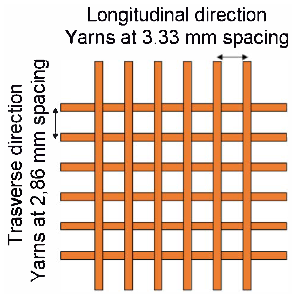
Figure 1. Jute fabric mesh opening.
Textiles 03 00008 g001
Figure 2. Treatment of jute fabric: (a) immersion in liquid PCM, (b) removal of PCM excess, and (c) coating by immersion in XSBR bath.
Textiles 03 00008 g002
Figure 3. Samples preparation: (a) dimensions for the direct tensile tests, (b) details of rubber sheets glued at specimens’ ends to avoid slippage during testing, and (c) yarn treatments.
Textiles 03 00008 g003
Figure 4. Composite layer distribution.
Textiles 03 00008 g004
Figure 5. Composite molding: (a) first layer of mortar, (b,c) fixation of jute fabric, (d) mortar layer penetration, and (e) last layer of mortar (e).
Textiles 03 00008 g005
Figure 6. Thermal behavior test: (a) composite specimens and (b) test setup.
Textiles 03 00008 g006
Figure 7. SEM cross-section images of (a) in natura, (b) XSBR-coated, and (c) PCM-impregnated and XSBR-coated jute yarns.
Textiles 03 00008 g007
Figure 8. CT scan images of jute yarns embedded in cement: microcentrifuge tubes (a); pores and voids detail (b).
Textiles 03 00008 g008
Figure 9. Evaluation of the effectiveness of the polymer coating on the jute fabrics: leakage of (a) in natura jute yarn and (b) XSBR-coated jute yarn, (c) mass and layer thickness during treatment and (d) mass loss after treatment.
Textiles 03 00008 g009
Figure 10. Typical curves from the tensile tests performed on jute yarns.
Textiles 03 00008 g010
Figure 11. FTIR spectroscopy of untreated and treated jute yarns.
Textiles 03 00008 g011
Figure 12. Thermogravimetric analysis curves: TG and DTG of raw and treated jute yarns.
Textiles 03 00008 g012
Figure 13. Four-point bending test of XSBR-coated jute fabric composite.
Textiles 03 00008 g013
Figure 14. Results of four-point bending tests on the composites: typical curves (a) and cracks formed during tests (b).
Textiles 03 00008 g014
Figure 15. Temperature profiles of studied composites submitted to thermal tests during heating and cooling cycles.
Textiles 03 00008 g015
Table 1. Physical properties of CrodaTherm 24.
PropertyTypical ValueUnit
Thermal properties by differential scanning calorimetry (DSC)
Peak melting temperature24°C
Latent heat (melting)184kJ/kg
Peak crystallisation temperature22°C
Latent heat (crystallisation)−182kJ/kg
Thermal properties by three-layer calorimetry (3LC)
Peak melting temperature23°C
Total heat capacity (melting)207kJ/kg
Peak crystallisation temperature23°C
Total heat capacity (crystallisation)213kJ/kg
Other properties
Bio-based content100%
Density at 20 °C (solid)906kg/m³
Density at 40 °C (liquid)843kg/m³
Flash point226°C
Specific heat capacity (solid)3.7kJ/kg °C
Specific heat capacity (liquid)2.2kJ/kg °C
Volume expansion 20–40 °C7.5%
Thermal conductivity (solid)0.22W/m °C
Thermal conductivity (liquid)0.16W/m °C
Thermal cycles without change in properties10,000cicles
Table 2. Mix proportions of the mortar.
ComponentMaterials Consumption (kg/m³)
Cement548
Metakaolinite438
Fly ash108
Sand548
Water438
Table 3. Tensile tests of studied jute yarns and fabric.
Textile Component    Tensile Strength (MPa)Elastic Modulus (MPa)
Yarn102 ± 184627 ± 739
Fabric (transverse)60 ± 172938 ± 220
Fabric (longitudinal)62 ± 193208 ± 704
Coated yarn118 ± 145508 ± 427
Coated yarn and PCM (liquid)61 ± 112160 ± 290
Coated yarn and PCM (solid)69 ± 92431 ± 258
Table 4. Thermal degradation temperature and residue at 1000 °C of untreated and treated jute.
TreatmentTi (°C)
3% Mass Loss
DTG
Main Peak (°C)
Residue at
1000 °C (%)
Raw jute2143504.8
XSBR3134254.3
XSBR + PCM1954376.7
Disclaimer/Publisher’s Note: The statements, opinions and data contained in all publications are solely those of the individual author(s) and contributor(s) and not of MDPI and/or the editor(s). MDPI and/or the editor(s) disclaim responsibility for any injury to people or property resulting from any ideas, methods, instructions or products referred to in the content.