Abstract
Many electronic textile (e-textile) applications require a stretchable basis, best achieved through knitted textiles. Ideally, conductive structures can be directly integrated during the knitting process. This study evaluates the influence of several knitting and material parameters on the resistance of knitted conductive tracks after the knitting process and after durability testing. The knitting speed proves to be of little influence, while the type of conductive thread used, as well as the knitting pattern both impact the resistance of the knitted threads and their subsequent reliability considerably. The presented research provides novel insights into the knitting process for conductive yarns and possible applications and shows that choosing suitable material and processing methods can improve the quality and robustness of knitted e-textiles.
Keywords:
e-textiles; knitting; reliability; smart textiles; conductive textiles; knitted conductors 1. Introduction
Electronic textiles (e-textiles) represent a growing group of hybrid textile products characterized by integrated electronic and conductive components. Main application areas for wearable e-textiles are sports, medical, personal protective equipment (PPE) and therapeutical purposes with the aim of measuring body functions and activities of the users [1]. Despite a wide range of application scenarios, challenges including comfort, stability against mechanical wear occurring during use (such as cyclic stretching and bending or abrasion), as well as washability have so far prevented e-textiles from reaching a wider market [2].
E-textiles intended for body monitoring, where continuously gathered data are used to improve training or therapy results, prevent strain or accidents, for diagnostics or to regulate integrated actuators, need to be especially flexible, stretchable, comfortable and washable [3]. The integrated sensor systems often need to be in direct contact to the user’s skin and should not impact the movement and the breathability of the garment. Compared to woven textiles, knits possess a much higher structural elasticity [4], making them ideal substrates for such form-fitting e-textile applications [5]. Yet, integrating circuits into a stretchable base—Without impacting the stretchability of the fabric—Is especially challenging. A promising approach to produce adequately elastic circuits is to knit them directly into the textile during production. This way, the circuit paths will have a comparable stretchability to the textile substrate. The advantage of this approach is a minimal impact on textile properties, making the e-textile more comfortable for users. No additional integration resources and processing steps are necessary, and almost no waste of conductive material occurs, making the knitting of conductive elements into a textile substrate fabric both sustainable and cost effective. Apart from textile circuits, conductive yarns knitted into textiles can also function as strain or touch sensors, electrodes, heating elements or induction coils [6,7,8].
During the knitting process and the subsequent use phase, the conductive yarns in such knitted e-textiles will experience a range of mechanical stresses, as well as strain from washing cycles. Research into the effects of knitting parameters on textile properties has been done extensively for non-conductive knitted textiles. Gosh et al. investigated the influence of yarn count and tension, speed and loop length on the comfort of jersey and rib knits [9]. Research by Ramachandran et al. shows that thermal properties of knits is dependent on the yarn type and different knitting parameters [10], while Nazir et al. show that tighter knitted interlock fabrics and smaller stitch lengths lead to better moisture management properties [11]. Other research looks into the influence of processing and material parameters of jersey textiles [12], just to name a few examples.
Yet, there is less insight for conductive yarns, as e-textile research and product development thus far was focused predominantly on creating circuits through embroidery, printing or laminating. Euler et al. investigated how different factors affect the contact impedance of knitted electrodes. Electrode size and shape, knit construction and the yarn density of the conductive yarn were varied, with size and construction showing the biggest influence [13]. The research of Atalay and Kennon shows that when knitting strain sensors, the input tension for the conductive yarns, but also the properties of the non-conductive base yarn used, will influence sensing capability. The number of parallel conductive lines also affects the sensor characteristics, but to a lesser extent [14]. The type of yarn and the density of conductive lines influences the suitability of the resulting fabric for heating application, as Repon et al. show [15]. Ullah et al. researched the suitability of different conductive yarns and knit structures for knitted pressure sensors, but did not evaluate the effect that different knitting parameters have on the integrity of the yarns and their resistance [16]. Overall, findings into the influence of knitting and material parameters when knitting with conductive yarns are limited, especially in combination with reliability considerations.
This research aims at bridging this gap in insight by evaluating how knitting parameters and different conductive yarns influence the resistance of knitted circuits during the production of the textiles and after a series of simulated wear scenarios. A higher knitting speed is suspected to lead to a higher mechanical strain during the knitting process, as other studies have shown a pronounced influence of processing speed when using embroidery to create textile circuits [17]. The second assumption tested in this research is that the knit structure influences the resistance of the finished knitted circuit, both due to different amounts of mechanical strain during the production process as well as a different amount of contact points in the conductive thread within the textile. The conductive yarn is also suspected to influence the quality of a knitted circuit, as different yarns will behave differently during production and the use phase. To simulate the use phase, the knitted textiles with integrated conductive tracks were subjected to cyclic stretch testing, wash cycles and a tensile test.
2. Materials and Methods
2.1. Main Parameter Test
The parameters knitting speed, conductive yarn type and knit construction type were analyzed to determine their effects on the resistance of knitted textile conductors directly after the knitting process.
Conductive yarns: The tested yarns were chosen from commercially available conductive yarns marketed as suitable for knitting. Four different silver (Ag) coated, nylon (PA) based materials were chosen from two suppliers: Elitex (ELITEX) (see Figure 1a,e) from IMBUT and Shieldex 33/10 (SHLD33) (see Figure 1b,f), Shieldex 44/10 (SHLD44) (see Figure 1c,g) and Madeira HC40 (MDR40) (see Figure 1d,h) from Statex. The Shieldex yarns SHLD33 and SHLD44 are comparable in all aspects except the yarn count. Both Shieldex yarns are too thin to be knitted as a single thread, so they were tripled during specimen production by leading the threads of three cones into a single yarn feeder of the Kniterate machine. To assess if twined yarn shows better results for knitted conductors than doubling or tripling 1-ply yarn, MDR40—A twine made of Ag-coated PA, also manufactured by Shieldex (but marketed as an embroidery thread)—Is tested as well. Compared to the Shieldex materials, ELITEX yarn from IMBUT has a thicker silver coating due to an additional, second coating step.
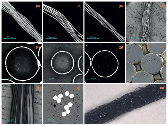
Figure 1.
Scanning electron microscopy (SEM) and cross-section images of the conductive and non-conductive yarns prior to the knitting process. Yarns: (a) ELITEX, (b) SHLD33, (c) SHLD44, (d) MDR40, (i) STEEL, (k) PA base yarn; Cross sections: (e) ELITEX, (f) SHLD33, (g) SHLD44, (h) MDR40, (j) STEEL.
Silver coated yarns are widely used in knitted, woven or embroidered e-textiles due to their textile-compatible properties, but often show unsatisfactory reliability results [18]. To compare a differently constructed yarn to the Ag-coated PA yarns, Steel-tech from supplier Amann was chosen as the fifth material, a yarn consisting of solid stainless steel wires twined with PA filaments (STEEL) (see Figure 1i,j). Table 1 gives an overview of the 5 different materials used for the test as well as the PA yarn used as a non-conductive base yarn for all test specimen (see Figure 1k). The electrical properties of the conductive yarns are also provided in the table.

Table 1.
Properties of utilized yarns.
Knitting speed: One of the assumptions motivating the presented research is that higher knitting speeds lead to increased mechanical strain (and subsequently to higher damages) on the yarn. The Kniterate machine used to produce the specimen is capable of knitting speeds up to 800 mm/s [19], which was the speed chosen as the maximum testing speed. For industrial production, the lowest possible knitting speed of 10 mm/s is much too slow and thus not feasible, so the lowest testing speed is set slightly higher at 100 mm/s. The default setting for the knitting speed when creating new designs with the Kniterate software is 300 mm/s [20], which is why two more testing speeds were set at 250 mm/s and 400 mm/s, respectively, slightly below and above this default value. The knitting speed for the non-conductive rows knitted from the black PA yarn is kept at a constant 400 mm/s.
Knit structure: In knitting, a distinction is made between four basic weft knits: single jersey (SJ), rib, interlock (IL) and purl (PU) [21]. Since all structures are formed differently, it is likely that the mechanical stress on the yarn also differs during their construction.
Single jersey (SJ): SJ consists of right loops that are knitted using only one needle bed [22]. As is illustrated in Figure 2a, SJ shows stitch legs and thus knit stitches on the face side and stitch heads and stitch feet and therefore purl stitches on the reverse side [22]. Single jersey has moderate stretchability (10–20%) in the longitudinal direction and high stretchability (30–50%) in the transverse direction [4]. SJ has the densest stitch structure of all four basic knitting types, since only one needle bed is used in production and no additional yarn length is generated during transfer between the needle beds, which is why the contact points of the conductive yarns are also the densest. Due to this property, the path of the lowest electrical resistance through the knitted fabric should be the shortest compared to the other three basic weft knits. Therefore, the electrical conductivity should be the highest, which makes SJ a relevant structure for e-textiles.
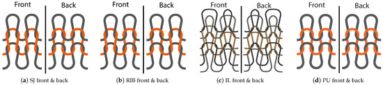
Figure 2.
Overview of knit structures, own representation based on [21].
Rib: The simplest version of the rib structure is the 1:1-rib (RIB) [21]. In the RIB structure, alternating wales of knit stitches on the front bed and knit stitches on the back bed (purl stitches on the right side of the fabric) are produced [20]. RIB has moderate stretchability (10–20%) in the longitudinal direction and very high stretchability (50–100%) in the transverse direction [4]. Due to the particularly high transverse elasticity and the high volume, RIB is suitable for use in strain sensors and pressure sensors and is therefore an interesting structure for e-textiles [23]. Both sides of the RIB show knit stitches, as can be seen in Figure 2b [4].
Interlock (IL): While some sources list IL as distinct type of basic weft-knit [21], other sources only include it as a sub-type of rib knit [24]. Since IL has a dimensionally stable structure due to its manufacturing method and is therefore interesting for the research and development of electronic circuit paths, in which few unwanted changes in resistance should occur due to changes in strain, it is treated and examined in this work as a basic type of knitting. Each row of IL requires two rows of stitches knit on separate alternating needles, creating two rows of half-gauge ribbing whose sinker loops cross over. Thus, odd feeders alternately knit wales on each side and even feeders knit the other wales [21]. IL has a moderate stretchability both lengthwise and crosswise [4]. IL has the same appearance on both sides, but its surface cannot be stretched to reveal the wales of the underlying stitch because the wales on each side are diametrically opposed and connected [21]. This means that knit stitches are visible on both sides of the fabric (Figure 2c) [4].
Purl (PU): PU is the fourth basic weft knitting structure. Both sides show purl stitches, as depicted in Figure 2d. During its production, a stitch transfer between the beds is carried out after each row of stitches [24]. Knitting PU samples on the Kniterate machine caused persistent problems and defects. For this reason, the PU structure was excluded from this research.
Table 2 gives an overview of all the parameters varied in the main parameter tests and the tested values. All possible combinations of knitting speed, knit structure and conductive yarns were tested. After the resistance measurement, the conductive tracks were evaluated for damages and defects using SEM microscopy.
Table 2.
Varied parameters for the parameter test.
2.2. Resistance Measurement
The resistance (and changes in resistance) was used to assess the influence of different parameters on the quality of knitted conductors presented in this research. The standard EN 16812—Textiles and textile products—Electrically conductive textiles—Determination of the linear electrical resistance of conductive tracks was used a basis for the measuring principle. The standard assumes stable measurements of the electrical resistance [25]. As knitted fabrics can experience relaxation over time due to their structural elasticity, we assumed that the electrical resistance might also be inconstant. Two preliminary tests were conducted to investigate the time dependent resistance changes in the knitted structures, and the suitability of the methods provided by EN 16812 within the framework of this research.
Preliminary test 1: A knitting speed segment (see Section 2.4) was knitted at 400 mm/s with ELITEX. Because the knitted fabric contracts after knitting, it was stretched back to the original 500 mm for the measurement. The resistance of each conductive track was monitored over the course of 5 min using a digital multi-meter. During the 5 min measurement, the electrical resistance steadily decreased at a low rate due to the relaxation of the fabric. This implies that no time-independent, constant measurement according to EN 16812 is possible.
Preliminary test 2: EN 16812 specifies that the contact should be improved if mechanical clamping does not lead to the necessary stability of the measurements. With a yarn, this is possible by using a crimp connector [26]. For this purpose, crimp connections were attached to both ends of all conductive tracks of the sample examined in preliminary test 1. This did not lead to an improvement in contact, since the loose structure of the knitted fabric prevents precise attachment of the crimp connections. Due to the loose structure of the knit, the crimp connector does not always fully enclose the conductive yarn. Therefore, the yarn ends were contacted to the multi-meter using clamps when conducting the resistance measurements (see Figure 3), a slight deviation from the methods provided in the standard.
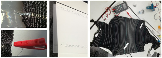
Figure 3.
Resistance measurement: unsatisfactory crimp connection (left, top), alternative method using clamps (left, bottom), fastening device (middle), fastening device with mounted test vehicle and multi-meter measuring setup (right).
Resistance test method: Since the preliminary tests 1 and 2 determined that the standard EN 16812 is not entirely suitable for the knitted samples, the test method employed to measure the resistance was adapted from the standard. Resistance measurements were taken as follows: all measurements were carried out in standard climate according to EN ISO 139 [27]. Samples were conditioned in the standard climate for 24 h prior to the test. The resistance of each conductor track was measured with a multi-meter. Since the samples contract lengthwise and crosswise after knitting due to their structural elasticity, a fastening device used to stretch the samples to a length of 50 cm was developed (see Figure 3). The device consisted of a board into which two lines of holes were drilled at short intervals with a distance of 50 cm between the lines. One test specimen could be mounted onto the board using pins that fit into the holes. Between mounting the sample and measuring the resistance, a waiting time of 1 min was established to avoid distorting the results due to high fluctuation of the measured values. Each conductive track was measured separately.
2.3. Quality and Reliability Testing
An e-textile not only experiences mechanical and other types of damaging influences during production, but also during the following use phase. Even though specific parameter combinations present as more suitable as a result of the main parameter test, it is possible that the conductive yarns have received damages during the knitting process that will only become apparent during the use phase, making them less suitable overall. To test how the different parameter combinations hold up under (simulated) use conditions, they were subjected to tensile testing, cyclic stretching and washing cycles.
Uni-axial tensile test: A uni-axial tensile test with simultaneous electrical resistance measurement was conducted using a TIRAtest 27025 to determine how the individual knit structures behave under quasi-static mechanical stress. Elongation properties, as well as the point from which on plastic and visco-elastic deformation occurs were established. Due to their specific structures, SJ, RIB and IL are expected to show different tensile behaviours. While the results of the tensile test are an indicator of the different knit structures’ mechanical properties, for the purposes of this research, they are mainly used to determine the maximum elongation for the cyclic tensile tests.
The test specimens (see Section 2.4) were first mounted on the upper clamp with their own weight tensioning them. The specimen was then mounted on the lower clamp. The conductor track was contacted at the top and bottom end to a resistance measurement unit, allowing for simultaneous recording of tensile and electrical data during the test. The specimens were stretched according to EN ISO 5271 at a rate of 100%/min [28]. Measurements were carried out until the specimen was completely torn.
Based on this test, an elongation suitable for the cyclic elongation test was determined: due to the differing structural elasticity of the knit structures, a fixed percentage of elongation for the subsequent cyclic strain tests (e.g., 200%) for all three types would not ensure equal amounts of strain. Instead, the results of the uni-axial tests were used to identify the elongation at 1 N for each knitting construction type and used as the target elongation for the cyclic tests, see example for RIB in Figure 4 (center). Up to a force of 1 N, the meshes are mainly aligned in the direction of tension when the textile is stretched. The yarn itself is subjected to only a very low tensile load while the threads slide over each other. Above 1 N, the yarn is mechanically stressed and the deformation passes into the visco-elastic range of the yarn. To remain in the area of mesh alignment, the strain amplitude used for the cyclic tests is the strain at which the yarn is exposed to a load of 1 N.
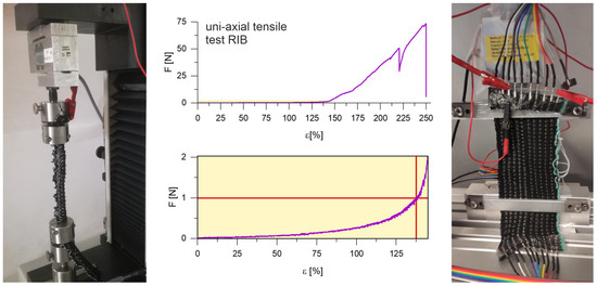
Figure 4.
Quality and reliability testing: uni-axial tensile test set-up and test specimen (left), determination of ε1N with tensile test results, example for RIB (center), cyclic stretch test set-up and test-specimen (right).
Cyclic strain testing: In the cyclic strain measurement test, the resistance behaviour of the conductor tracks was examined under repeated mechanical stress. Prior to testing, all conductor tracks of a test specimens were contacted using crimp connections and connected to the resistance measuring device of the cyclic strain tester (see Figure 4 (right)). After the contacted specimen was mounted to the upper and lower clamps of the tester, it was subjected to 10,000 stretch cycles with a maximal elongation εmax equal to the elongation at 1 N strain taken from the measurements of the uni-axial tensile test (values for εmax for each of the three knit structures can be found in Section 3.2). The electrical resistance was measured for each cycle at an elongation of 0 (ε0) and at εmax. The relative changes in resistance at 0 (Rrel,n,0) and maximum elongation (Rrel,n,max) for each cycle were calculated to assess the stretching reliability of each combination of material and knitting structure, with
and R0 being the initial resistance of each track prior to testing.
Due to the long duration of the strain test, testing was carried out only with a few representative parameter combinations (see also Section 2.4). After 10,000 strain cycles, surface changes and possible damages to the conductive structures of the test specimens were evaluated using scanning electron microscopy (SEM).
Wash testing: As washability represents a key property for wearable e-textiles [2], the knitted tracks were subjected to wash testing. The washing protocol used to assess the washability of the different knitted tracks is an e-textile wash testing protocol developed by Rotzler et al. [29], based on the textile washing standard ISO 6330 [30]. Table 3 gives an overview of the washing procedure which is representative of gentle household washing. Prior to the first wash cycle, the initial resistance R0 for each test specimen was measured using the protocol described in Section 2.2. Afterwards, the samples were washed 10 times, with further resistance measurements being taken after 5 and 10 washing cycles. The relative change in resistance Rrel after n wash cycles was used as an indicator of washability, calculated according to Equation (1). Prior to the initial resistance measurement as well as the measurements after 5 and 10 cycles, the test specimens were conditioned in a standard atmosphere for 24+ h [27]. To evaluate damages to the yarns and the conductive coating due to washing, an X-ray and SEM microscopy analysis of the test specimen was carried out after the 10th wash cycle.
Table 3.
Wash testing protocol.
2.4. Test Specimen
All test specimens were knitted on a Kniterate machine using the corresponding design software to create the digital knitting files [31]. A Kniterate machine is a 7 gauge double bed digital flatbed knitting machine capable of knitting six different yarns per design. Kniterate has 252 latch needles per bed (504 in total) and is operated with its own design software [20]. The maximum knitting speed is 800 mm/s and the lowest knitting speed 10 mm/s [19].
Main parameter test: The test specimen for the main parameter test were designed to contain all possible combinations of the three tested parameters. To achieve this, they were built up from multiple segment tiers.
- Knit structure segment: The smallest parameter segment is the knit structure segment which is knitted entirely from one of the three structures SJ, RIB or IL. Each segment contains five rows knitted with conductive yarn separated by eleven non-conductive rows to avoid electrical interference (see Figure 5a).
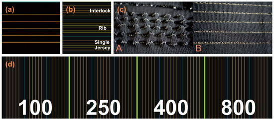 Figure 5. Knit structure, knitting speed and yarn segments. (a) Schematic representation of a knit structure segment; (b) Schematic representation of a speed segment with knit structure segments; (c) Buckling in SJ test specimen: A STEEL, B MDR40; (d) Schematic representation of a yarn segment with speed segments.
 - Knitting speed segment: Each knitting speed segment consists of three knit structure segments—One for each structure—And is entirely knitted in one of the chosen knitting speeds (see Figure 5b).
- Conductive yarn segment: The largest segment is the conductive yarn segment that combines the knitting speed segments for all chosen knitting speeds with each other. All conductive rows within this segment are knitted entirely with one of the conductive yarns (see Figure 5d). This yields five conductive yarn segments in which all parameter combinations for the specific yarn are contained.
To achieve the target width of 50 cm for the resistance measurement, each course consisted of 250 stitches. One complete conductive yarn segment was 1091 courses long. All four silver coated yarns incorporated well into the knitted structure and the conductive tracks did not impact the subjective feel of the fabric. The stainless steel yarn is stiffer and less flexible and exhibited significant buckling in the finished samples, especially prominent in the SJ parts where the radius of the loop of the knit stitches is smallest (see Figure 5c). Apart from the buckling, the STEEL tracks also have a less textile feel and are more noticeable to the touch in the knitted textile compared to all the silver coated yarns.
Tensile Test: The most relevant parameter for the elongation in the transverse direction is the knit structure. Thus, all three types (SJ, IL, RIB) were examined in the uni-axial tensile test, while knitting speed and yarn type were not varied. All three specimens were knit at a medium speed of 400 mm/s and ELITEX was used as the conductive yarn because it is closest to the PA-yarn in terms of maximum tensile load (according to suppliers’ information). The sample width of 20 mm is preset by the geometry of the tensile test machine. Since the sample is clamped in the transverse direction, this width determines the number of courses. The testing length is set to 100 mm, but the specimen must be designed long enough to ensure reliable gripping. The size of the specimen is thus set to 11 courses (the middle of which is knitted with the ELITEX yarn), and 100 wales, for a total length of 200 mm. Three specimens are knitted for each of the three knit structure types (a total of 9 test specimen), see Figure 4, left.
Cyclic Stretching: In this test all knit structures as well as 4 of the yarns—ELITEX, SHLD44, STEEL and MDR40—Were examined. Since SHLD33 and SHLD44 differ solely in the number of conductive filaments, only SHLD44 is examined. The size of the test specimen is restricted by the geometry of the clamping device of the stretch tester, a test bench for the qualification of stretchable circuit carriers [32]. The maximum sample width is 140 mm, the distance between the upper and lower clamping device is 100 mm. For each specimen, 5 tracks from 2 of the yarns were knitted, a total of ten conductor tracks per specimen (see Figure 4, right). With one test specimen per knit structure with 2 yarn types each, a total of 6 test specimens were knitted. The number of knitted courses was determined by the specimen being clamped in the transverse direction. With ten tracks per specimen, the course count was 87, corresponding to a width of 174 mm (as the samples contract after knitting, this was compatible with the target width of 140 mm of the clamp). The wale count is set at 125, corresponding to a length of 250 mm. This length covers the expansion range of 100 mm and enables contacting and clamping. All six specimens were knitted with a speed of 400 mm/s.
Wash Test: As the results of the main parameter tests (see Section 3.1) showed only a very minor influence of the knitting speed, wash testing samples were only produced with the middle knitting speed of 400 mm/s that was also used to knit the cyclic stretch testing samples. One knitting speed segment as described above (see Figure 5b) was produced for each of the 5 conductive yarns. A second SHLD44 sample knitted at a the highest speed of 800 mm/s was made to investigate if the knitting speed has an influence on the washing reliability of knitted conductors.
3. Results
3.1. Main Parameter Test
The results of the parameter tests indicate how different knitting speeds and knit structures influence the resistance of knitted conductors after the knitting process for the conductive yarns SHLD33, SHLD44, ELITEX, STEEL and MDR40. Figure 6 shows the relative difference in resistance (Rrel, see Equation (1)) in relation to the knitting speed for all yarns and knit structures, with the respective value for R at the slowest speed (100 mm/s) as the baseline R0. In Table 4, the mean values for R for all different combinations are given.
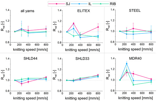
Figure 6.
Resistance after knitting for different speeds, knit structures and yarns.
Table 4.
Mean resistance of the knitted tracks for all combinations after knitting.
Figure 6 shows that, averaged for all yarns, the difference in resistance for the tested knitting speeds is very low for all three knit structures. For 250, 400 and 800 mm/s, the resistance is (on average) within 5% of the resistance for 100 mm/s. When looking at the yarns separately, SHLD33, SHLD44 and STEEL show less than 10% deviation from the value of R at 100 mm/s for any speed and knit structure. The values for both SHLD yarns are less scattered than for STEEL. ELITEX and MDR40 show more fluctuation. At 250 mm/s, resistance is between 15 and 30% higher than at 100 mm/s for MDR40; yet for 400 and 800 mm/s, values for R are again at a similar level as for 100 mm/s. ELITEX also shows a peak at 250 mm/s for SJ and IL, followed by a drop at 400 mm/s. This suggests that for those two yarns, a slow to medium speed is more damaging than a very slow or very fast speed.
The knit construction has the second highest effect on the resistance after the yarn type. As expected, RIB and IL lead to a higher resistance than SJ (see Table 4). This can be attributed to two factors. On the one hand, between a quarter and a third less conductive yarn is needed to knit an SJ track of the same length compared to RIB and IL. On the other hand, SJ has a much denser structure than the tracks in RIB and IL, potentially leading to more contact points of the yarn within the track.
3.2. Tensile test
Table 5 gives an overview of the tensile test results with standard deviations (SD), and Figure 7 shows resistance, full tensile results and—enhanced—The section from 0 N up to 1 N for one test cycle for IL and SJ. From the three knit structures SJ is the least stretchable with an elongation at break of 125%. The RIB structure is twice as stretchable, and more than three times as stretchable before 1 N of tensile force acts on the test specimen. Contrary to the data from the literature—See knitting structures in Section 2.1—The stretchability of IL exceeds that of SJ, and the experimentally obtained results for RIB also exceed the value given in the source [4]. This could be attributed IL and RIB having a larger loop size compared to SJ. The former are both knitted on both beds while SJ is only knitted on one. With the Kniterate, the use of both beds leads to a larger actual loop size, even though the loop size for all three structures is the same when compiling the knitting file with the software. So the ratio of loop size and yarn diameter is larger for IL and RIB, resulting in a looser knit structure which can explain their relatively high stretchability.
Table 5.
Results of uni-axial tensile test.
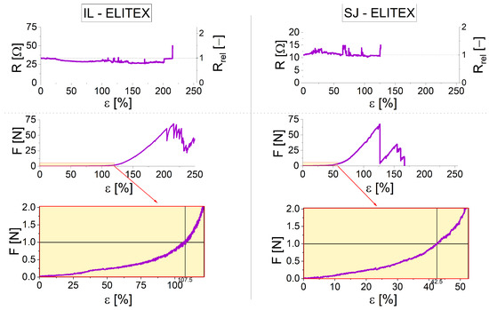
Figure 7.
Exemplary tensile test results with resistance values for SJ and IL.
The force at break also increases with higher elongation at break, but the differences are not as distinct with the force at break at 67.3 N for SJ, 68.8 N for IL and 73.6 N for RIB. The values for elongation at 1 N are used as the target elongation εmax for each structure in the subsequent cyclic stretch tests.
For all three knit structure types, the resistance barely changes apart from fluctuations and a sudden sharp increase before complete failure. See Figure 7—Topmost graphs—For exemplary resistance results of IL and SJ; results for RIB show a comparable resistance behaviour. This might indicate that the yarn does not have many contact points with itself (as the yarn gets pulled apart during the tensile test, those contact points would decrease and the resistance thus increase).
3.3. Cyclic Stretch Testing
The results of the cyclic stretch testing show the relative change in resistance Rrel over the course of 10,000 test cycles for both Rε0 and Rεmax. Figure 8 shows the results of all four tested yarns (SHLD33 was not tested) for SJ, with a maximum elongation of εmax of 42.5% (see also Section 3.2). For MDR40 and SHLD44, the results for RIB and IL are also depicted, with εmax at 137.5% and 107.5%, respectively. While both SHLD44 and STEEL show very stable results across all 10,000 cycles for SJ; ELITEX and MDR40 exhibit a considerable increase in resistance over time: up to 3 times the initial value of resistance at εmax for MDR40, up to 6.5 times for ELITEX, up to 2 times the initial value at ε0 for MDR40 and 3 times for ELITEX. ELITEX also shows significantly higher increases than all other tested yarns for the other two knit structures, with values for Rrel,max of up to 7 (IL) and 5 (RIB). Rrel,max does not exceed 1.5 for both IL and RIB for MDR40, while the results for SHLD44 and STEEL show the same stability for IL and RIB as for SJ.
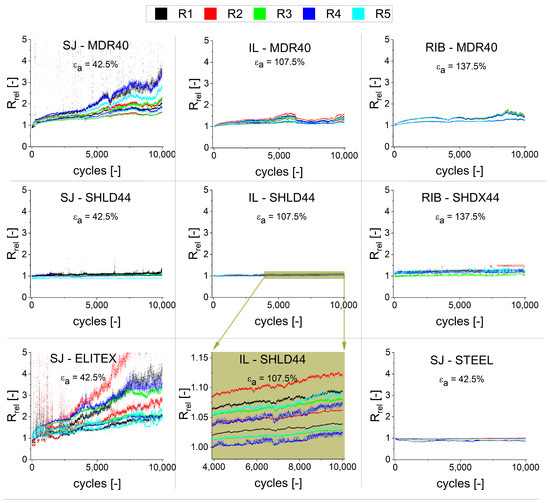
Figure 8.
Relative change in resistance for different combinations after stretch testing.
The most stretchable structure, RIB (see Table 5), shows the overall best results (and thus the best suitability) under cyclic strain, while the least stretchable material, SJ, shows the poorest suitability for cyclic stretching. There is a notable difference ΔR between the resistance at ε0 and εmax for ELITEX for all three structures (with a pronounced steady increase in ΔR with an increase in cycles). For MDR40, ΔR is equally notable, but less pronounced: for SJ, the difference increases steadily just like for ELITEX. For RIB and IL, ΔR increases more slowly after an initial rise within the first few 100 cycles. For SHLD44, ΔR is small but almost constant across all three knit structures. Even at higher cycle counts, ΔR is very stable and shows little variation, see enhanced SHLD44-IL results in Figure 8, middle image, bottom row. STEEL shows a very different behaviour than the Ag-coated yarns; ΔR between ε0 and εmax is almost 0 across the 10,000 cycles for all three structures.
3.4. Wash Testing
Following the initial resistance measurement (R0), the test specimens were washed for five cycles without drying in between the cycles. After the 5th cycle, the test specimens were dried lying flat, and conditioned for 24 h prior to measuring the resistance R5. This was repeated once for a total of 10 cycles, and the resistance R10 was measured at the end of the tests for each conductive track of each test specimen.
During the wash cycles, the test specimen became entangled with each other due to loose ends of threads from the beginning and endpoint of the knitted structures, as well as floats of thread (primarily of the conductive threads) on the sides of the test specimen. After the 5th cycle, the samples were still intact, though, and resistance measurements were taken as described in Section 2.2. After the 10th cycle, some of the threads of the conductive tracks had been pulled out to some extent, shortening the remaining track and thus potentially skewing the resistance measurement of the shortened tracks. To alleviate this, the resistance measurements were first taken as described on the shortened tracks. After measuring, the threads of the shortened tracks were pulled out of the fabric, their remaining length measured and compared to the length l of an intact track. The amount of length decrease (lredu) was then used as a correction factor to recalculate a corrected R10,corr for the shortened tracks as follows
For some of the tested combinations (see Figure 9), the resistance after 10 wash cycles is lower than after five wash cycles, though. This indicates that either the measuring method is not precise and reliable enough, the correction factor for the shortened tracks depends on more than just the reduced length (e.g., a higher count of contact points in shortened tracks) or that due to the washing, resistance of the tracks can decrease (due to yarn relaxation or washing-related shrinkage of the fabric). The very large fluctuations for the SHLD44/400–RIB at 5 cycles and much lower results for 10 cycles suggest that an issue with the measuring method is likely to be accountable for at least some of these fluctuations.
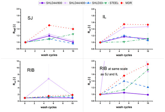
Figure 9.
Relative change in resistance for different knit structures after wash testing.
Similar to the main parameter test, ELITEX showed the worst results out of all yarns. For the RIB structure of the ELITEX sample, all five tracks were defective after only five wash cycles. For the IL structure, there was an average increase in resistance by a factor of 28 after five cycles and all tracks were defective after 10 cycles. All except one of the SJ tracks still showed function after 10 cycles, with an average increase in resistance of the remaining tracks of more than 1300%. These results indicate a poor washability of the ELITEX yarn, and the material is thus excluded from the subsequent comparison of results between yarn types.
Looking at the other yarns, all tracks still show function after 10 cycles and the mean relative change in resistance Rrel does not exceed 2 for any of the combinations. MDR40 exhibits the overall highest increase of resistance after 10 cycles, with Rrel between 1.4 and 1.9 after 10 cycles (see Figure 9). The two SHLD yarns at 800 mm/s knitting speed showed the best washing results, with Rrel not exceeding 1.2 after 10 cycles. The results for SHLD44 at 400 mm/s knitting speed are slightly worse, and exhibit in part large fluctuations. Rrel for STEEL is between 1.1 and 1.7. Contrary to the other yarns, the results for STEEL for the SJ structure are worse than for IL, which could be caused by the yarns’ buckling behaviour (see Section 2.4) and resulting additional mechanical strain. The results for SHLD44 at 400 mm/s knitting speed are slightly worse, and exhibit in part large fluctuations. This could indicate that—Contrary to the initial hypothesis—A fast knitting speed leads to slightly less damages and a subsequently better washing reliability, but could also be the cause of resistance measuring issues as stated above, or a combination of the two factors. When comparing the different knit structures, RIB shows both the worst and the largest spread of results of all the structures (see Figure 9, bottom row). IL and SJ show comparable washability.
3.5. Damage Analysis
Figure 10 gives an overview of all yarns before and after knitting, as well as after the cyclic stretch and washing tests. The SEM images show damages to yarns in the form of loss of Ag-coating for SHLD yarns, MDR40 and ELITEX. As the (visible) damages are very similar across the different knit structures, only the results for SJ are shown.
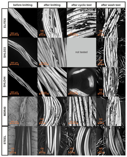
Figure 10.
SEM damage analysis of the five conductive yarns before and after knitting and after cyclic and wash testing for SJ (cyclic testing was not done with SHLD33 yarn).
While the Ag-coating for ELITEX is almost intact prior to knitting, after the knitting process there is already noticeable damage in the coating, cracks and larger pieces that have chipped off. After washing and cyclic stretching, the loss of Ag-coating is even more pronounced. Both SHLD yarns show very little damage after the knitting process, and much less damage compared to ELITEX after cyclic stretching and wash testing. From all the yarns, MDR40 has the most initial damage to the Ag-coating, which does not increase a lot by the knitting process only. After cyclic stretching and wash testing, the damage is more pronounced, with visible scrapes and cracks in the Ag-coating. The damage of the RIB sample after cyclic stretching is more extensive than for IL and SJ, in line with the resistance results. Compared to ELITEX, the Ag-loss in the SHLD and MDR40 yarns looks to be rather in the form of scrapes than chipped-off larger pieces and mostly the result of abrasion, see Figure 10. This may suggest a poorer adhesion of the Ag to the PA core for ELITEX, possibly due to the thicker Ag-layer and a resulting higher stiffness.
It is unclear what kind of mechanism is responsible for the resistance increase of the STEEL yarn after washing, as—In contrast to the Ag-based yarns—There is no metal coating that can be lost (the wires in the yarn are solid metal), as the SEM images (Figure 10) show. The STEEL yarns should thus be more resistant to mechanical wear compared to the Ag-coated yarns, as losses in conductivity can only occur as a results of damaged or torn wires. An X-ray microscopy analysis revealed no apparent breaks in the individual wires of the yarn after 10 wash cycles (Figure 11). Possible scenarios are breaks in the wires too small to detect by the maximum resolution of the X-ray microscope, or cracks and tears that are not full breaks, but nevertheless impact conductivity. Corrosion or oxidation are unlikely, due to the inert nature of the stainless steel.
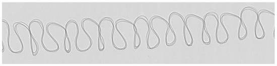
Figure 11.
Xray microscopy image of a SJ STEEL track after 10 wash cycles showing no damages to the steel filaments.
4. Discussion
An increase in the parameter knitting speed does not cause a clear increase or decrease in the resistance of the knitted conductor tracks. The subsequent damage analysis also did not show an increase in damage of the conductive coating across different knitting speeds. This refutes the assumption made at the beginning of this paper that the knitting speed negatively influences the resistance. For some of the materials, a speed of 250 mm/s leads to the highest resistance, indicating that a middle to low speed is less suitable than very low or high knitting speeds—Yet the differences are still quite low. The wash test results for SHLD44 also suggest that a higher knitting speed may lead to long term better reliability results. This means that the knitting speed for conductor tracks for the examined knit structures and yarn types can be chosen to match the knitting speed of the rest of the textile. Likewise, the most economical (the fastest) knitting speed of 800 mm/s can be used to produce knitted conductor tracks.
Using a different yarn results in the most significant resistance changes of all parameters. The type of coating, the durability of the coating under mechanical stress, the construction of the yarn (yarn or twine, composition, number of filaments) and the tear strength (SHLD yarns had to be tripled) play a role in the yarns’ electrical behaviour after knitting. Due to a second Ag-coating step, ELITEX has the lowest initial resistance out of all the tested yarns. Yet, the thicker coating appears to make the yarn much more susceptible to mechanical stresses and resulting damages to the conductive coating. As a result, ELITEX exhibits poor fastness to use-case related stresses and even the production process itself and is thus not well suited for knitted applications. While STEEL is both stable after knitting and reliability testing (especially cyclic stretching) and has relatively good conductivity, the yarns’ higher bending stiffness impacts the textile feel, structure and comfort. This makes the yarn potentially unsuitable for applications where the conductive elements knitted into a textile should blend seamlessly into the fabric and are worn close to the body or for knitted conductive structures with a larger area (such as heating pads or electrodes).
Apart from STEEL, the SHLD yarns have proven to be the most reliable out of all tested yarn types under the tested conditions. They show the least fluctuation in resistance value between tracks knitted under the same conditions and after cyclic stretch testing. Compared to STEEL, tracks knitted with SHLD yarns possess a more textile quality and are thus more suitable for applications were comfort of the user is of importance. The resistance of the yarns and the resulting knitted elements is around 4–6.5 times higher for SHLD33 and SHLD44 than for STEEL (see Table 4), which limits their applicability for some e-textile use cases that require highly conductive circuits. A possible solution is to not only triple the SHLD yarns (as was done on this research), but to use quadrupled or even quintupled yarn, lowering the resistance with every additional ply—This approach may not be implementable with all knitting machines, though. When looking at both SHLD yarns, SHLD33 and SHLD44 show very similar results after knitting and washing (cyclic testing was only conducted with SHLD44), which indicates that both yarns are equally suitable for knitting, and that a higher or lower filament diameter does not impact the stability of the Ag-coating of the yarns. As the resistance of SHLD44 is significantly lower than that of SHLD33, it will be the better choice for applications with higher conductivity requirements. Even though it was assumed that Ag-coated yarns are less reliable and more prone to damages compared to a stainless steel yarn with solid metal wires (see Section 2.1 and [18]), results show that SHLD yarns are equally reliable under the tested conditions.
MDR40 is not unsuitable for knitted conductor tracks, but less so than SHLD and STEEL, due to a lower stretching and washing stability. Advantages of MDR40 over the SHLD yarns are the significantly lower resistance and an easier production due to the yarn being already twined and thus not needing multiple bobbins to be fed into the knitting machine. Wash testing results for MDR40 with embroidered test specimen—Conducted with the same washing protocol—Show only slightly worse results for Rrel after 10 wash cycles [33], indicating either that both the knitting and embroidering process exert similar strain on the conductive yarn, or that the reliability of the conductive tracks is not influenced by these processes to a large extent. In the experiment with the embroidered conductors, 20 wash cycles were run in total, with the resistance increasing more rapidly after the 10th cycle. Further testing with the knitted conductors is necessary to evaluate if the washing reliability will follow the same pattern. After a longer exposure to washing related stress, it is also possible that the results for STEEL and the silver based yarns will differ more, with STEEL possibly being more reliable in the long run.
In terms of knit structures, SJ shows the best resistance results after knitting out of all the tested structures, but exhibits the least stretchability and cyclic stretching reliability. This makes SJ the most suitable knit structure for use cases that do not require a high stretchability. On the other hand, while RIB has an excellent cyclic stretching reliability, is is less stable towards washing than the other two structures. IL shows both a good stretchability of more than 200% and good reliability towards washing and cyclic stretching, making it the preferable choice for highly stretchable applications over RIB.
Textile strain sensors have been identified as a possible application scenario for knitted conductors [8,14]. Knitted conductors suitable for such sensor applications need to show a stable and significant difference in resistance ΔRε within the target range of elongation from ε0 to εmax,target [8]. From the tested combinations, RIB and IL tracks knitted with SHLD44 show very promising behaviour for strain sensing, as ΔR is very stable across the full 10,000 cycles for both knit structures and shows very little variation between the five tracks of the test vehicle (see Figure 8, middle image, bottom row). Although the cyclic stretching tests have only been conducted with one of the SHLD materials, is is expectable that SHLD33 will be just as suitable as SHLD44, given the overall very similar results for both yarns. A decrease in loop size/yarn diameter ratio might increase sensing capabilities, as it can lead to more initial contact points due to a tighter structure. On the other hand, a tighter structure could lead to lower stretchability/εmax (see Section 3.2 and Section 3.3) and thus a reduced possible sensor range.
ELITEX has such a low stretching reliability that it is unsuitable for sensors; in combination with IL and RIB, MDR40 might be suitable for strain sensors, yet ΔR is less stable across a large number of cycles than for SHLD44. The SJ structure is not suited for strain sensors with MDR40 and ELITEX, and less suited than RIB and IL for SHLD44.
As the test vehicles were only stretched within the range of purely elastic deformation (see Section 2.3), ΔR is mainly a result of a change in contact points within the lines of conductive yarns. As the loops get pulled apart, the number of contact points decreases and the resistance increases [14]. In contrast to the Ag-coated yarns, ΔR is almost 0 for the STEEL yarn, rendering the material unsuitable for strain sensing. This resistance behaviour can be explained by the different composition of the STEEL yarn: solid stainless steel filaments combined with non-conductive filaments. On the one hand, the non-conductive filaments will insulate the steel filaments from each other to some extent, leading to less contact points between them even in an non-stretched state. On the other hand, as the conductive elements of the STEEL yarn are full metal filaments (compared to just very thin layers on the outside of the PA-filaments for the Ag-coated yarns), the resistance is less impacted by the small—Compared to the diameter of the metal filaments—Contact points between the single filaments. A change in contact points brought about by stretching will thus not lead a large change in resistance.
These results confirm previous research on knitted strain sensors. Atalay et al. also found SJ and stainless-steel filament yarn to be not well suited for strain sensor applications, but obtained good results with an IL structure and Ag-coated yarn [14,34] while Raji et al. achieve reliable sensor structures with Ag-coated yarn and different rib structures (among them 1:1 rib) [35].
Table 6 summarizes the results of the presented research by giving an overview of the suitability of the different tested structures and yarns for different application and reliability scenarios of knitted e-textiles.
Table 6.
Suitability of knit structures and materials for different scenarios.
5. Conclusions
The presented research into the influences of different processing and material parameters on the quality and reliability of knitted conductor tracks presents novel insights that can serve as a basis for future developments of stretchable, knitted e-textiles and textile sensors. The knitting speed has been shown to only have a very small influence on the electrical resistance of the conductors. The choice of yarn and the knit structure has a more decisive influence on the reliability. Depending on the target application, the combination of material and structure has to be selected to achieve best results.
To gain wider insight into the topic, additional conductive yarns should be examined, though, especially newer generations of hybrid yarns, that feature very thin protective encapsulations that might protect the conductive material from mechanical strain, increasing their reliability. Likewise, other, less basic knit structures with more complexity should be tested, as there is potential to find structures that lead to better reliability results. Industrial knitting machines are capable of higher knitting speeds than the maximum of 800 mm/s of the Kniterate. Investigations into the results with more industrial machines and higher knitting speeds could lead to different results concerning knitting speed influence on the quality and reliability of knitted conductors.
Some tested combinations showed good washing stability but poor results from stretch testing. Yet, during a projected use-case, both types of wear are likely to occur. Combined reliability testing such as first subjecting the test specimen to cyclic stretch testing before conducting wash tests may thus yield a better estimate of the suitability of different combinations of material, process and structures.
Author Contributions
Conceptualization, E.E., J.M. and S.R.; methodology, S.R.; validation, E.E., M.v.K. and S.R.; formal analysis, J.M.; investigation, J.M., L.W. and S.R.; resources, M.v.K. and S.R.; data curation, J.M., S.R. and L.W.; writing—original draft preparation, J.M. and S.R.; writing—review and editing, E.E., M.v.K., J.M., S.R. and L.W.; visualization, J.M., S.R. and L.W.; supervision, E.E. and S.R. All authors have read and agreed to the published version of the manuscript.
Funding
This research received no external funding.
Data Availability Statement
Additional data available upon request.
Conflicts of Interest
The authors declare no conflict of interest.
Abbreviations
The following abbreviations are used in this manuscript:
| Ag | Silver |
| IL | Interlock |
| PA | Polyamide/nylon |
| PPE | Personal protective equipment |
| SEM | Scanning electron microscope |
| RIB | 1:1 rib knit |
| SD | Standard deviation |
| SJ | Single jersey |
References
- Ohnemus, J.; Rasel, F. FashionTech—Smart Textiles; Zentrum für Europäische Wirtschaftsforschung GmbH: Mannheim, Germany, 2018. [Google Scholar]
- Rotzler, S.; Kallmayer, C.; Dils, C.; von Krshiwoblozki, M.; Bauer, U.; Schneider-Ramelow, M. Improving the washability of smart textiles: Influence of different washing conditions on textile integrated conductor tracks. J. Text. Inst. 2020, 111, 1766–1777. [Google Scholar] [CrossRef]
- Libanori, A.; Chen, G.; Zhao, X.; Zhou, Y.; Chen, J. Smart textiles for personalized healthcare. Nat. Electron. 2022, 5, 142–156. [Google Scholar] [CrossRef]
- Horrocks, A.; Anand, S. Handbook of Technical Textiles; Woodhead Publishing Series in Textiles; Woodhead Pub: Cambridge, UK, 2000; Volume 12. [Google Scholar]
- Angelucci, A.; Cavicchioli, M.; Cintorrino, I.A.; Lauricella, G.; Rossi, C.; Strati, S.; Aliverti, A. Smart Textiles and Sensorized Garments for Physiological Monitoring: A Review of Available Solutions and Techniques. Sensors 2021, 21, 814. [Google Scholar] [CrossRef] [PubMed]
- Chen, A.; Tan, J.; Tao, X.; Henry, P.; Ziqian, B. Challenges in Knitted E-textiles. In Proceedings of the AIFT 2018: International Conference on Artificial Intelligence on Textile and Apparel, Hong Kong, China, 3–6 July 2018; pp. 129–135. [Google Scholar] [CrossRef]
- Fobelets, K.; Thielemans, K.; Mathivanan, A.; Papavassiliou, C. Characterization of Knitted Coils for e-Textiles. IEEE Sens. J. 2019, 19, 7835–7840. [Google Scholar] [CrossRef]
- Jansen, K.M.B. Performance Evaluation of Knitted and Stitched Textile Strain Sensors. Sensors 2020, 20, 7236. [Google Scholar] [CrossRef] [PubMed]
- Ghosh, A.; Mal, P.; Majumdar, A.; Banerjee, D. Analysis of Knitting Process Variables and Yarn Count Influencing the Thermo-physiological Comfort Properties of Single Jersey and Rib Fabrics. J. Inst. Eng. Ser. E 2016, 97, 89–98. [Google Scholar] [CrossRef]
- Ramachandran, T.; Manonmani, G.; Vigneswaran, C. Thermal behaviour of ring- and compact-spun yarn single jersey, rib and interlock knitted fabrics. Indian J. Fibre Text. Res. 2010, 35, 250–257. [Google Scholar]
- Nazir, A.; Hussain, T.; Ahmad, F.; Faheem, S. Effect of Knitting Parameters on Moisture Management and Air Permeability of Interlock Fabrics. Autex Res. J. 2014, 14, 1578. [Google Scholar] [CrossRef]
- Fatkić, E.; Geršak, J.; Ujević, D. Influence of Knitting Parameters on the Mechanical Properties of Plain Jersey Weft Knitted Fabrics. Fibers Text. East. Eur. 2011, 19, 87–91. [Google Scholar]
- Euler, L.; Guo, L.; Persson, N.K. Textile Electrodes: Influence of Knitting Construction and Pressure on the Contact Impedance. Sensors 2021, 21, 1578. [Google Scholar] [CrossRef] [PubMed]
- Atalay, O.; Kennon, W.R. Knitted Strain Sensors: Impact of Design Parameters on Sensing Properties. Sensors 2014, 14, 4712–4730. [Google Scholar] [CrossRef] [PubMed]
- Repon, M.R.; Laureckiene, G.; Mikucioniene, D. The Influence of Electro-Conductive Compression Knits Wearing Conditions on Heating Characteristics. Materials 2021, 14, 6780. [Google Scholar] [CrossRef] [PubMed]
- Ullah, S.; Shaker, K.; Hamdani, S.T.A. Optimization of Knitted Structures for E-Textiles Applications. Eng. Proc. 2022, 15, 18. [Google Scholar] [CrossRef]
- Zheng, Y.; Jin, L.; Qi, J.; Liu, Z.; Xu, L.; Hayes, S.; Gill, S.; Li, Y. Performance evaluation of conductive tracks in fabricating e-textiles by lock-stitch embroidery. J. Ind. Text. 2020, 51, 6864S–6883S. [Google Scholar] [CrossRef]
- Dils, C.; Werft, L.; Walter, H.; Zwanzig, M.; von Krshiwoblozki, M.; Schneider-Ramelow, M. Investigation of the Mechanical and Electrical Properties of Elastic Textile/Polymer Composites for Stretchable Electronics at Quasi-Static or Cyclic Mechanical Loads. Materials 2019, 12, 3599. [Google Scholar] [CrossRef] [PubMed]
- Kniterate. Machine Manual Version 2.1.6. 2022. Available online: https://support.kniterate.com/hc/en-us/categories/360001185978-Manual (accessed on 14 June 2022).
- Kniterate. Kniterate Support. 2022. Available online: https://support.kniterate.com/hc/en-us (accessed on 14 June 2022).
- Spencer, D.J. Knitting Technology: A Comprehensive Handbook and Practical Guide, 3rd ed.; Woodhead Publishing Limited: Cambridge, UK, 2004. [Google Scholar]
- Weber, K.P.; Weber, M.O. Wirkerei und Strickerei: Technologische und Bindungstechnische Grundlagen, 5th ed.; Deutscher Fachverlag: Frankfurt am Main, Germany, 2008. [Google Scholar]
- Koncar, V. (Ed.) Smart Textiles and Their Applications, 1st ed.; Woodhead Publishing Limited: Cambridge, UK, 2016. [Google Scholar]
- Samuel, R. Flat Knitting Technology; Rees: Heidenheim, Germany, 1993. [Google Scholar]
- CSN EN 16812:2016; Textiles and Textile Products—Electrically Conductive Textiles—Determination of the Linear Electrical Resistance of Conductive Tracks. European Committee for Standardization: Brussels, Belgium, 2016. [CrossRef]
- ISO 4921:2000; Knitting—Basic Concepts—Vocabulary. International Organization for Standardization: Geneva, Switzerland, 2000.
- ISO 139:2005; Textiles—Standard Atmospheres for Conditioning and Testing. International Organization for Standardization: Geneva, Switzerland, 2005.
- ISO 527-1:2019; Plastics—Determination of Tensile Properties—Part 1: General Principles. International Organization for Standardization: Geneva, Switzerland, 2019.
- Rotzler, S.; Schneider-Ramelow, M. Development of a Testing Protocol to Assess the Washability of E-Textiles. Solid State Phenom. 2022, 333, 3–10. [Google Scholar] [CrossRef]
- ISO 6330:2012; Textiles—Domestic Washing and Drying Procedures for Textile Testing. International Organization for Standardization: Geneva, Switzerland, 2012.
- Kniterate. Kniterate Software. 2022. Available online: https://design.kniterate.com (accessed on 8 August 2022).
- Born, S. Konzeptionierung und Realisierung eines Prüfstandes zur Qualifizierung von Dehnbaren Schaltungsträgern. Bachelor’s Thesis, Technische Universität Berlin, Berlin, Germany, 2010. [Google Scholar]
- Schulze, J.A. Evaluierung der Nutzungseigenschaften Gestickter Leiterbahnen im Simulierten Gebrauchsfall von E-Textiles. Bachelor’s Thesis, Hochschule für Technik und Wirtschaft HTW Berlin, Berlin, Germany, 2022. [Google Scholar]
- Atalay, O.; Tuncay, A.; Husain, M.D.; Kennon, W. Comparative study of the weft-knitted strain sensors. J. Ind. Text. 2017, 46, 1212–1240. [Google Scholar] [CrossRef]
- Raji, R.K.; Miao, X.; Zhang, S.; Li, Y.; Wan, A. Influence of Rib Structure and Elastic Yarn Type Variations on Textile Piezoresistive Strain Sensor Characteristics. Fibres Text. East. Eur. 2018, 26, 24–31. [Google Scholar] [CrossRef]


Publisher’s Note: MDPI stays neutral with regard to jurisdictional claims in published maps and institutional affiliations. |
© 2022 by the authors. Licensee MDPI, Basel, Switzerland. This article is an open access article distributed under the terms and conditions of the Creative Commons Attribution (CC BY) license (https://creativecommons.org/licenses/by/4.0/).