Article

Effect of X-Cable Bracing on the Optimized Weight of Planar Steel Frames Under Wind Load: A Parametric Study

by
Mustafa Al-Bazoon
1,
Saba Jasim Al-Rubaye
1,
Faten I. Mussa
1,
Abdulkhaliq A. Jaafer
1,
Lateef Assi
2,* and
Mohanad M. Abdulazeez
3
1
Department of Civil Engineering, College of Engineering, University of Misan, Amarah, Maysan 62001, Iraq
2
UES, 6995 Sierra Center Pkwy, Reno, NV 89511, USA
3
School of Science and Engineering, UMKC, 5110 Rockhill Road, Kansas City, MO 64110, USA
*
Author to whom correspondence should be addressed.
Constr. Mater. 2026, 6(3), 26; https://doi.org/10.3390/constrmater6030026
Submission received: 2 February 2026 / Revised: 6 April 2026 / Accepted: 17 April 2026 / Published: 27 April 2026

Abstract

In designing tall buildings, the primary concern is ensuring an effective lateral load-resisting system in addition to the gravity load system, since it largely governs the overall design. This study investigates the influence of X-cable bracing on the structural weight of tall steel frame buildings subjected to service and wind loading. Three numerical case studies, 10-story, 20-story, and 30-story planar steel frames, were modeled and analyzed using SAP2000, then optimized using Differential Evolution (DE) and Enhanced Colliding Bodies Optimization (ECBO) algorithms. These designs were evaluated under both service and wind load conditions, considering strength and drift constraints. The results indicate that the inclusion of wind loads in addition to service loads leads to a higher total structural weight than considering service loads alone, while cable bracing effectively reduces the overall mass by up to 6%, 38%, and 20% for the 10-story, 20-story, and 30-story frames, respectively, compared to unbraced structures, by improving the internal force distribution among structural components. Strength demands, reflected by the interaction ratio, governed all design cases, while lateral displacement was always less than the maximum limit according to AISC and ASCE requirements. Overall, the results highlight the potential of cable bracing systems to deliver efficient tall building designs; however, further studies are needed to generalize these findings to a broader range of building configurations.

1. Introduction

As cities expand and space in highly populated cities becomes scarcer, space demands are met with the construction of tall buildings. Tall buildings, with their increased height, are challenged with providing lateral load resistance. Such structures are influenced by appreciable wind forces, leading to lateral displacements, shear forces, and bending moments, for which measures must be taken for the stability and safety of the building. In addition to ensuring structural stability, limiting lateral displacement (drift) is crucial for serviceability to maintain occupant comfort and prevent damage to non-structural elements such as cladding and partitions. Thus, the design of efficient lateral load-resisting systems is important for retaining the functionality and the safety of tall buildings. Beyond performance gains, improving structural efficiency also lowers material demand and embodied carbon, which supports wider sustainability efforts within the construction industry. Over time, repeated exposure to lateral loads can result in cumulative damage if the building lacks adequate resistance. There are many types of lateral support systems, such as shear walls, bracing frames, outriggers, diaphragms, cable bracing, and a combination of them. Each system is selected based on many factors, such as building location, height, and architectural requirements [1].
Cable bracing systems date back to the early 20th century but gained significant popularity in the late 20th century due to advances in materials and computational modeling. The introduction of high-strength steel cables, which could carry large tensile forces, provided an alternative to traditional bracing systems made of solid steel members. Tall structures subjected to wind loads benefit greatly from cable bracing systems because of their high strength-to-weight ratio. By distributing lateral forces throughout the structure, they improve stability, reduce deflection, and guard against structural damage without placing an undue amount of weight on the structure. Thus, these systems provide an effective lateral support solution [2].
Cable bracing systems have been investigated because of their potential to reduce a building’s total weight without sacrificing its capacity to withstand lateral forces. Lotfollahi and Alinia [3] compared Tension-Braced Moment-Resisting Frames (TBMRFs) under lateral loads. The paper determined sequential failure modes and concluded that by introducing tie bracing, ductility improves and preferable collapse mechanisms are produced compared to unbraced frames. Saleem [4] proposed an external cable bracing system for tall buildings, inspired by the harped cable arrangement used in cable-stayed bridges. A 60-story building was analyzed under a wind speed of 146 mph (as recommended for Miami, FL by the Florida Building Code) using SAP2000. The study compared rigid frame, shear wall, and shear wall–cable bracing configurations. The results demonstrated that replacing exterior shear walls with cables effectively controlled lateral displacement and inter-story drift within allowable limits, while also reducing construction time and increasing usable interior space. The study also noted that the cable bracing system is more effective for buildings with smaller height-to-width ratios. A study by Jagadish and Doshi [5] compared several bracing systems. Single-diagonal bracing, X-bracing, double X-bracing, K-bracing, and V-bracing were discussed in high-rise steel buildings. STAAD.Pro was used to analyze a G+15-story building with wind loads of 33 m/s. The findings show that X- and double X-bracing performed the best, effectively reducing displacement and improving structural stiffness when K and V systems showed greater displacement due to structural irregularities. Patil et al. [6] compared a G+19 tall building under wind load conditions. The paper noted that forces caused by wind increase stress in beams and columns, leading to higher reinforcement demand and higher bending moments, while story drifts remain within permitted limitations. Similarly, Rajas and Shelke [7] compared reinforced concrete buildings of different bracing schemes under wind loading conditions. The paper concluded that it is not only the type of bracing involved that contributes to lateral resistance, but also its location at the frame, and noted that X-bracing at effective locations produces the best results. Alaghmandan et al. [8] introduced a computational workbench integrating architectural parametric design (AutoLisp), CFD simulation (ANSYS 14.5), and structural analysis (SAP2000) to optimize tall building forms under along-wind effects. The study examined tapering modifications ranging from −3 to 8 degrees on a 360 m, 90-story building using framed tube and diagrid structural systems. The results showed that increasing the tapering angle reduced base shear, base moment, and windward pressure, with the framed tube system exhibiting a weight difference of approximately 14 million kg between the minimum and maximum tapering cases. Diagrid systems, however, showed minimal sensitivity to tapering modifications. Park et al. [9] applied the database-assisted design (DAD) method to investigate wind effects on a 49-story, 238 m tall building with a square cross-section and mid-side columns, modeled similarly to the Citicorp Building. Using wind tunnel pressure data from the Tokyo Polytechnic University database, the study compared structural responses under face winds and corner winds. The results showed that corner winds produced along-wind and across-wind overturning moments approximately 20% and 50% lower, respectively, than face winds. Peak axial forces in the mid-side legs and demand-to-capacity indexes of chevron braces were also 20–30% lower for corner winds, confirming that face winds governed the design of square-plan tall buildings. Fanaie, et al. [2] studied the application of cable–cylinder bracing to reinforce steel moment-resisting frames under seismic loads. The study explains that the cable–cylinder system reduces axial forces in columns, minimizes residual displacements, and improves energy dissipation in comparison with conventional cable cross-bracing. It also provides better drift distribution across building height, helping prevent soft-story failure. The study shows that cable–cylinder bracing offers a more efficient, ductile, and economical retrofit option for enhancing the seismic performance of mid-rise buildings based on nonlinear time history analysis. Giaccu and Caracoglia [10] carried out research on pre-tensioned cable bracing systems. This research explores how slackening impacts structural dynamics, using the Equivalent Linearization Method (ELM) to analyze the problem. A key contribution is the introduction of a performance coefficient (ranging from 0.5 to 1.0) that measures stiffness reduction. According to the study, applying more pressure prevents members from coming loose, improving the stability and predictability of the structure’s response. Fanaie and Zafari [11] suggested a new cable–cylinder bracing system for seismic strengthening of steel frames. The sensitivity analysis reveals that the response modification factor is influenced by cable prestressing. The system demonstrates higher ductility and energy dissipation compared to traditional cross-cable bracing. Naghavi [12] studied three bracing systems: double-channel cross braces, cross cable braces, and cable braces with a cylindrical steel sheath, which are used to retrofit steel moment frames. ABAQUS is used to analyze the seismic performance of the frame under cyclic loading. It is shown that the cylindrical steel sheath preserves ductility and initial stiffness comparable to a moment frame. Moreover, this method stops buckling and lowers column axial forces, making it a complete seismic retrofit solution that does not lose ductility or require major foundation work. Rooshenas and Barghian [13] examined a novel bracing system to enhance seismic performance in moment-resisting frames. The suggested system combines the flexibility of moment-resisting frames with the lateral resistance of cable braces. The numerical analyses of 1-, 3-, and 6-story frames show a reduction in drifts. A study conducted by Mosaddegh [14] shows that cable bracing system with a central steel plate can be cost-effective solution for seismic resilience. However, experimental validation and further studies on diverse configurations are recommended. The results of reinforced concrete and steel frames modeled using SAP2000 demonstrate that the system enhances yielding strength, stiffness, and energy dissipation.
Prior research concerning cable bracing has predominantly centered on seismic applications, specifically investigating systems like cable bracing subjected to cyclic loading. These studies revealed significant enhancements in structural ductility, energy dissipation capabilities, and drift control. Simultaneously, the structural optimization of steel frames employing metaheuristic algorithms has been widely studied; nevertheless, the majority of these investigations have focused on unbraced frames or frames incorporating conventional rigid bracing systems, usually under gravity or seismic loading scenarios. Consequently, the effect of X-cable bracing on the optimized structural weight of tall steel frames subjected to wind loads while simultaneously satisfying strength and serviceability (drift) requirements has not been systematically investigated. Furthermore, the existing literature lacks direct quantitative comparisons between unbraced and cable-braced configurations evaluated under identical wind loading conditions.
To address this gap, this study explores how cable bracing systems could reduce the total weight of tall steel building structures while maintaining or enhancing lateral stability. This study follows previous studies that show X-type bracing as providing the best solution in terms of lateral drift reduction and stiffness increase in comparison with other bracing systems, such as V and K. This work utilizes X-cable bracing as the primary lateral load-resisting system. The analytical work encompasses a structural response analysis of X-cable-braced frames, alongside employing optimization schemes in an effort to achieve weight minimization. One of the main objectives is to promote sustainable design practices by minimizing material use and achieving more economically sound building practices. By comparing optimized unbraced and braced configurations under identical loading and constraint conditions, the study quantifies the weight-saving potential of X-cable bracing and provides insights into member utilization and constraint activity. The findings contribute to more material-efficient and sustainable tall building designs. To the best of the authors’ knowledge, this has not been done before.


2. Materials and Methods

A tall building is generally defined as a structure that exceeds 12 stories or 35–50 m in height. Analyzing and designing tall buildings requires considering the sway at the top of a building due to wind. This lateral deflection may be insignificant compared to the building height; however, those who occupy the top feel it strongly [15]. Thus, in the design process, not only the strength requirements for structural members but also the lateral displacement at the highest node of the structures must be considered.
The adopted methodology follows four main stages: (i) modeling a tall steel structure using SAP2000 (version 23.2.0) and Python 3.14, (ii) applying service (dead and live) and wind loads, (iii) using Differential Evolution (DE) and Enhanced Colliding Bodies Optimization (ECBO) algorithms to find the best solution, and (iv) comparing unbraced and X-cable-braced configurations. It should be noted that this study focuses solely on structural performance and optimization outcomes. The cost of cable bracing materials and installation was not considered. The following sections will go over the steps for each level in detail. This study focuses solely on structural efficiency and weight minimization; thus, material and installation costs are considered outside its scope.

2.1. Structural Modeling

In order to simplify the analysis and accurately capture the fundamental structural behavior under service and lateral loads, the numerical examples were represented as planar frames. Planar frames isolate the fundamental lateral behavior and significantly reduce computational cost compared to full 3D models. This lets metaheuristic algorithms thoroughly explore the design space. For regular buildings, such as the frames considered in this study, where dynamic amplification is low, linear static analysis is the norm for wind-load design. It also fits with the serviceability (drift) limits that apply to tall buildings. SAP2000, a popular finite element analysis (FEA) program, was used to create the models, while the bracing system was modeled as cable elements, which can only withstand tension forces. Namely, each cable is tension-only truss element that automatically becomes inactive in compression to ensure cables add stiffness to the structure only in tension and no additional nonlinear effects (e.g., slackening) were included. Columns and beams were represented as frame elements with assigned W-sections. Table 1 presents a summary of the structural elements and materials employed in the models, wherein the use of ASTM A992 Grade 50 steel means the yield strength is 345 MPa. The base of the structure was assumed to be fixed, simulating a rigid foundation. In all design examples, the story height was taken as 4 m, and the bay width as 6 m.

2.2. Service and Wind Loads

Loads are significant for keeping the building’s structure stable and secure. In this study, dead load, which stands for the permanent loads due to building self-weight and other permanent components, is assumed as 30  k N / m . Live load, which represents the temporary and movable loads such as occupants, furniture, and equipment, is taken as 12  k N / m , representing a commercial building. Wind loads as lateral forces are calculated based on a wind speed of 100  k m / h  (27.78  m / s ) at 10 m height, building bay of 6 m, and air density of 1.225  k g / m 3 . The following equations are used to determine the wind speed profile and velocity pressure [17,18,19]:
V ( z )   =   V 10   z 10 α
q ( z ) = 0.5   ρ   V z 2
where  V  is the mean wind velocity ( m / s ),  z  is the height ( m ),  V 10  is the wind velocity at a height of 10 m,  α  is a dimensionless number that varies with atmospheric conditions and terrain (taken as 0.25),  q  is the velocity pressure, and  ρ  is the air density (1.225  k g / m 3 ). Table 2 presents the wind force on five stories only.

2.3. Design Criteria

Two types of constraints are imposed on the structure: strength and displacement constraints. According to AISC [16], symmetric members subjected to axial force and bending must satisfy the interaction ratio (in SAP2000, it is called PMM ratio):
P u ϕ P n + 8 9 M u y ϕ b M n y 1 0     if     P u ϕ P n 0.2 P u 2 ϕ P n + M u y ϕ b M n y 1 0     if     P u ϕ P n < 0.2
where  ϕ  is the resistance factor, with  ϕ  = 0.85 for compression and  ϕ  = 0.90 for tension. The flexural resistance factor is  ϕ  = 0.90.  P u  and  P n  are the required and nominal axial strengths (tension or compression) in kN. The necessary flexural strength is  M u y  (kN-m).  M n y  is the nominal flexural strength in kN-m. At every location along the axis of every member in the structure, the constraints in Equation (3) must be followed. So, the equation shows that there are an endless number of limitations. In the numerical procedure, the restrictions are checked at different positions along the member’s axis, and they are put in place at the point where they have the highest values. Then, the penalty function is checked using these constraint values.
In tall building design, the maximum allowable lateral sway (drift) is controlled by building codes to ensure both structural safety and occupant comfort. ASCE [17], AISC [20], and the International Building Code (IBC) [21] are recommended a maximum allowable lateral drift under wind load between  H / 400  and  H / 600 , where  H  is the total building’s height. The normalized form of this criterion is as follows:
| | m a x 1
where   is the horizontal displacement at the top of the structure due to wind load, and  m a x  is the allowable displacement. In this study,  m a x  is taken as  H / 500 .

2.4. Simulation and Optimization

This work evaluates and improves the performance of tall steel buildings with X-cable bracing systems using both simulation and optimization methodologies. SAP2000 was used for simulations. As discussed earlier, the model takes into consideration dead, live, and wind loads. To simulate the actual conditions the structure will face throughout its lifetime, wind loads were incorporated. The building’s response to the applied service and wind loads was analyzed using linear static analysis. This type of analysis is appropriate for wind loads on regular structures where dynamic amplification is minimal and serviceability checks (drift) are the primary concern. Linear static analysis is standard in preliminary design and optimization frameworks. While more advanced analyses (e.g., material nonlinearity, nonlinear dynamic response) could be integrated with metaheuristic algorithms, they would drastically increase computational time. The Open Application Programming Interface (OAPI) is employed to connect Python-coded frame design examples with the SAP2000 structural analysis software. The Python scripts automate tasks like optimization, result gathering, and adjusting design parameters. This enables efficient exploration of different design configurations and speeds up the overall design process.
To minimize the structural weight of the building while ensuring sufficient lateral stability, metaheuristic optimization algorithms were applied. Discrete variables and non-differentiable functions can be handled routinely in these methods, and the search is not restricted to the vicinity of the current design. They are sometimes referred to as the global optimization approach [22,23] because they employ random search throughout the design space rather than gradient-based search in the neighborhood of the present point. The AISC [16] W-shapes found in the manufacturer’s catalog are preferred for beams and columns as design variables. According to Arora [24], these design variables fall under the category of linked discrete variables. In other words, all of the cross-sectional characteristics are known from the tables once the section number is known. The goal of this optimization method is to reduce the structure’s overall mass:
M ( X ) = n m = 1 N M m n m n k = 1 N K L n k
where  M  is the total weight of the structure,  X  is the design vector, NM is the total number of member groups for the structure,  m n m  is the weight per unit length of the members in the nmth group (available in AISC’s tables), NK is the number of members in the nkth group, and  L n k  is the length of the nkth member. Metaheuristic optimization algorithms deal with unconstrained objective functions to improve designs. One way of treating constraints in metaheuristic algorithms is to combine constraints with the cost function to define a merit function (also called the penalty function) [25,26,27]. The merit function quantifies how much a design solution fails to satisfy the imposed constraints, with larger values indicating greater deviations from the allowable strength or drift limits. In this study, it is defined as follows:
O b j X = M X 1 + 10 × P X ξ
P ( X ) = κ = 1 Κ m a x ( 0 , p κ )
where  O b j X  is the objective function,  P ( X )  is a constraint violation function,  ξ > 1  is the penalty function exponent (in this study,  ξ = 2 ), and  m a x ( 0 , p κ ) 0  is the violation value of the  κ t h  inequality constraint.
Two optimization algorithms are used to find the best design for the numerical examples: Differential Evolution and Enhanced Colliding Bodies Optimization. Both algorithms are multi-agent systems that start with a random population (designs) and continue improving iteratively. These algorithms were selected because of their proven robustness in structural optimization problems and their ability to effectively handle discrete steel sections, nonlinear constraints, and large design spaces [28,29,30,31]. The following subsections briefly discuss both algorithms. Since the main goal of this research is to discuss the effect of bracing on the structural weight of tall buildings, the algorithms’ pseudocode and equations are omitted.

2.4.1. Differential Evolution (DE)

The Differential Evolution (DE) optimization algorithm is a metaheuristic method for solving complicated optimization problems. DE perturbs candidate solutions with scaled vector differences between randomly selected population members, balancing exploration and exploitation to iteratively modify candidate solutions according to evolution differences [32,33]. Through this process, the algorithm is able to strike a balance between exploring new regions of the search space and taking advantage of promising solutions, ultimately leading to the best solution. It is a useful tool in many domains, including engineering, due to its versatility in solving both continuous and discrete optimization problems [34]. Four parameters need to be adjusted for DE: crossover rate, mutation factor, maximum number of iterations, and population size. Following a few trial runs of the problems, these parameters were set to 0.7, 0.5, 100, and 20, respectively, for better results. The number of function evaluations, called SAP2000 for structural analysis, in each iteration is 40 analyses with 100 iterations plus the initial population; therefore, the total number of structural analyses per optimization run is 4020.

2.4.2. Enhanced Colliding Bodies Optimization (ECBO)

Natural collisions are the basis for the Colliding Bodies Optimization (CBO) algorithm, which was created by Kaveh and Mahdavi [27]. When two objects collide in this process, they gravitate toward a minimal energy level. Conceptually, the CBO is straightforward, independent of internal parameters, and memory-free for storing the best-so-far solutions. A memory step is introduced to speed up ECBO’s convergence compared to normal CBO in Enhanced Colliding Bodies Optimization (ECBO), which enhances CBO to produce quicker and more dependable solutions. Altering a few colliding body components will also aid ECBO in escaping local minima [35]. ECBO has demonstrated its effectiveness in solving a wide range of engineering problems [26,36].
ECBO requires three parameters: the escaping from local optima factor (0.25), the maximum number of iterations (200), and the population size (20). Similar to the DE, these parameters are set based on a few trial runs of the problems using ECBO. Consequently, the total number of structural analyses per optimization run amounts to 4020, which is comparable to that of DE. A large number of analyses were necessary for each run to ensure the convergence of the metaheuristic algorithms to a near-global optimum for this complex, discrete, and nonlinear optimization problem.

3. Design Examples

Three design examples are studied to show the advantages of cable bracing systems in tall buildings subjected to wind loads. These case studies are a 10-story, 3-bay steel frame, a 20-story, 5-bay steel frame, and a 30-story, 3-bay steel frame. SAP2000 is used to analyze both examples under service and wind loads and strength and serviceability specifications. Planar frames were utilized to isolate the essential lateral behavior and facilitate effective parametric optimization, a standard initial phase in tall building research. Three-dimensional effects and torsional responses are recognized as significant yet deferred for subsequent investigation.
The DE and ECBO algorithms are utilized to minimize the overall structural weight while ensuring compliance with strength and serviceability requirements. The use of these two well-established algorithms increases confidence in the results. For each frame, results are compared between X-braced and unbraced configurations, highlighting how the inclusion of cable bracing enhances structural efficiency and reduces lateral displacements.

3.1. First Design: 10-Story, 3-Bay Frame

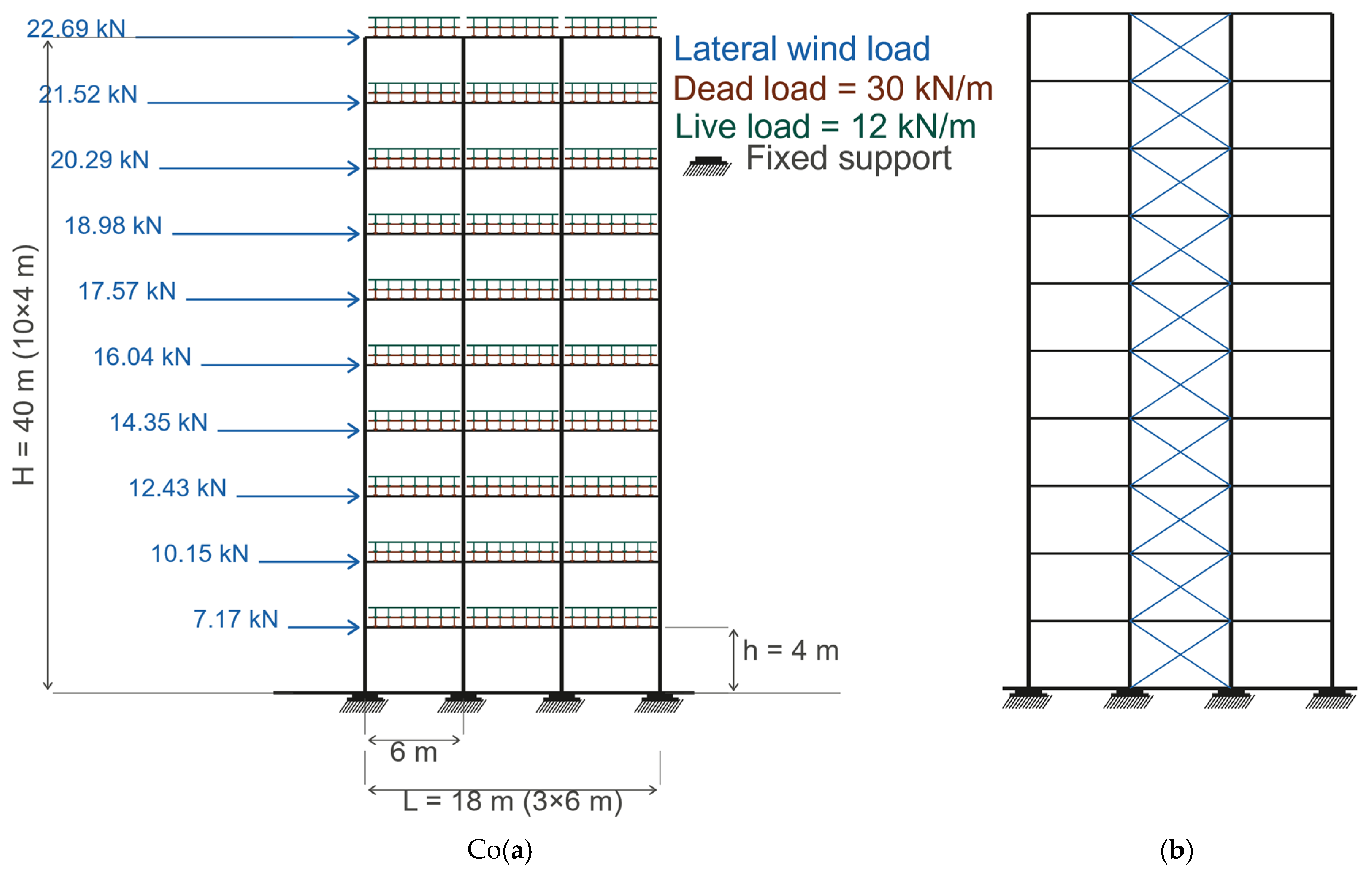
A steel moment frame with three bays and ten stories makes up the first design example. The beams are subjected to uniformly distributed service loads, consisting of a dead load of  30   k N / m  and a live load of  12   k N / m . As seen in Figure 1a, wind load is represented as concentrated lateral forces operating at the top of each story (calculated according to the procedure outlined in Section 2.2). As shown in Figure 1b, X-shaped cable bracing is only placed in the middle bay for the braced configuration. There are eleven design variables in the structural model: (i) the first design variable is represented by a single beam group, in which every beam has the same cross-section, (ii) the remaining ten design variables are represented by ten column groups, one group per story (Table 3). The AISC [16] manufacturer’s catalog lists the lightest 100 W-sections from which member sections are chosen. This strategy guarantees a realistic design. Three configurations are studied: (i) unbraced frame subjected to service loads only and AISC’s strength requirements, (ii) unbraced frame subjected to service and wind loads and AISC’s strength requirements, and (iii) braced frame subjected to service and wind loads with AISC’s strength and displacement requirements  ( m a x = ( 4000 × 10 ) / 500 = 80   m m ), as shown in Table 3. For each case study, two optimization runs were performed for both algorithms to ensure that the best design was obtained. In Table 3, the bold values indicate the best design among the four runs. The last two rows of the table summarize the maximum PMM ratio (with its location) and the maximum drift at the roof level, together with the load case that produced it.

3.2. Second Design: 20-Story, 5-Bay Frame

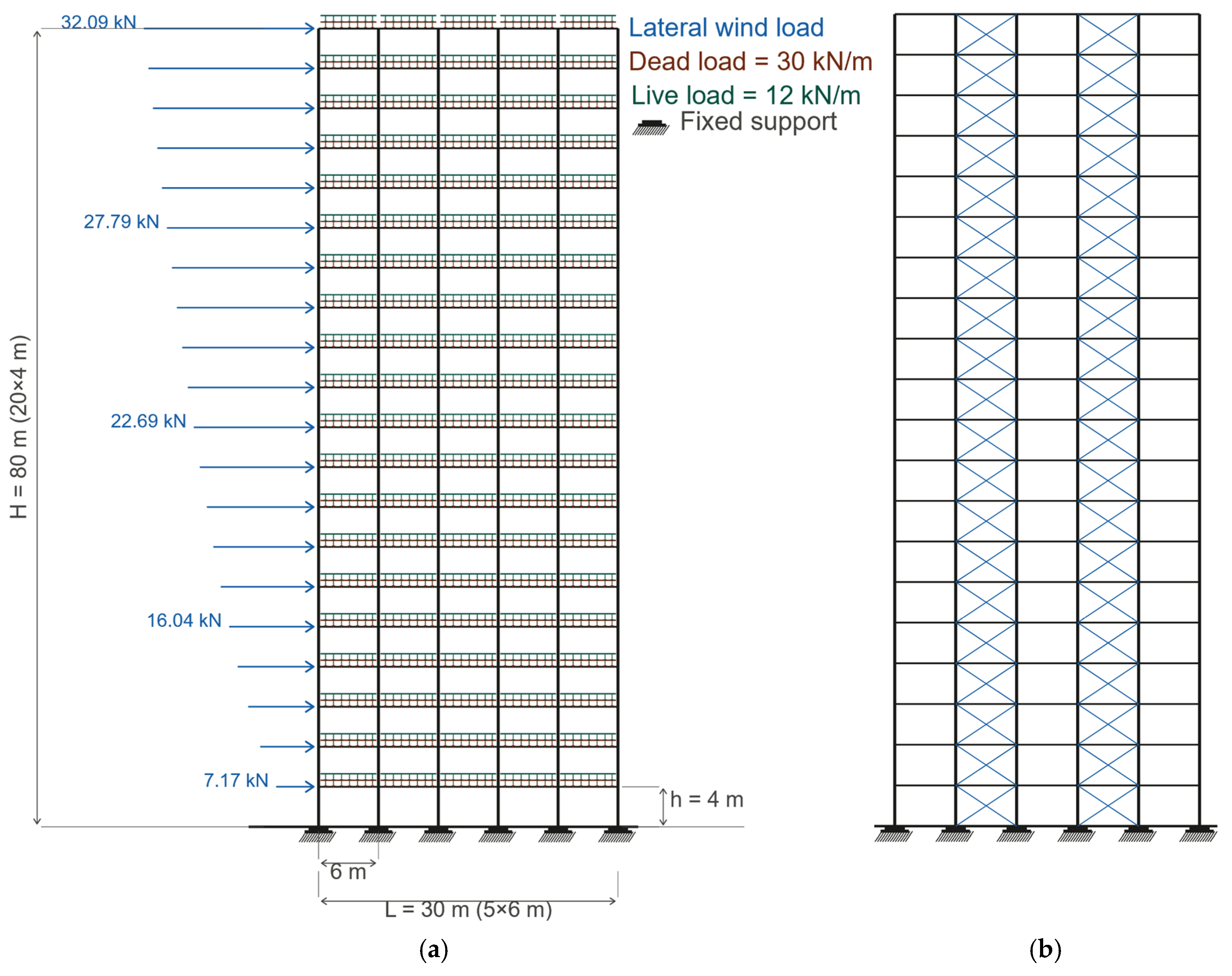
A steel moment frame with 5 bays and 20 stories is the second design example. Each story has a height of 4 m, and each bay spans 6 m. Service loads are applied as uniformly distributed loads on beams, with a dead load of  30   k N / m  and a live load of  12   k N / m . Wind loads are calculated following the procedure in Section 2.2 and applied as concentrated lateral forces at the top of each story (see Figure 2). Similarly to the first example, three different setups and 11 design variables are discussed (Table 4). However, since there are 20 stories, the following setups are used: (i) one beam group (all beams have the same section), which is the first design variable; (ii) ten groups of columns, one for two stories, which show the other ten design variables. The lightest 150 W-shapes in the AISC [16] manufacturer’s catalog are chosen for member sections.
The DE and ECBO algorithms are used to find the lightest structure that still meets AISC [16] strength and wind drift limits  m a x   =   ( 4000 × 20 ) / 500 = 160   m m ). Table 4 shows the best designs for each case, along with the total weight, maximum PMM ratio, and maximum drift for each design.

3.3. Third Design: 30-Story, 5-Bay Frame

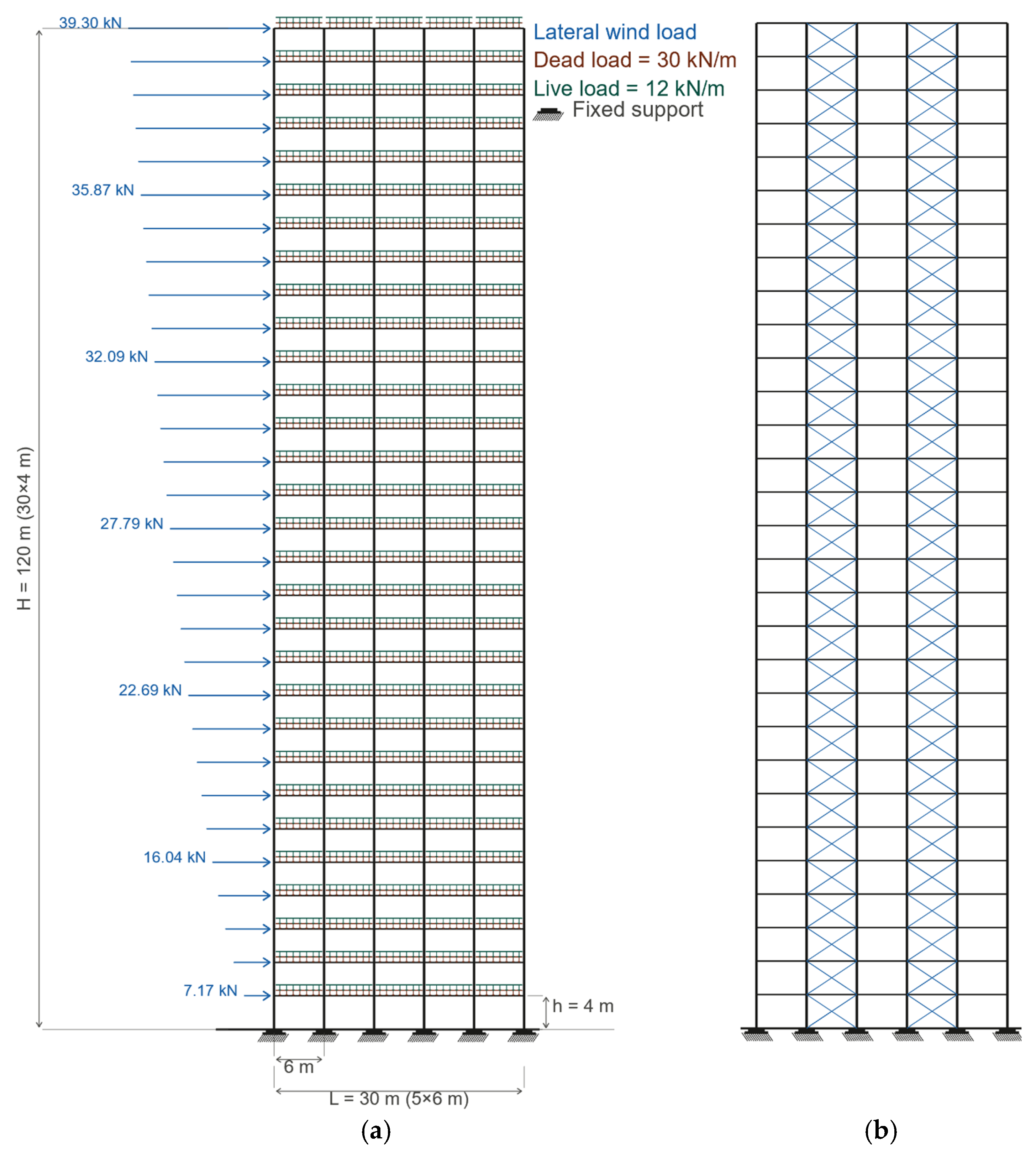
The third and tallest design example is a steel moment frame with 5 bays and 30 stories. Each story has a height of 4 m, and each bay spans 6 m, giving a total building height of 120 m. Service loads are applied as uniformly distributed loads on beams, with a dead load of 30 kN/m and a live load of 12 kN/m. Wind loads are calculated following the procedure in Section 2.2 and applied as concentrated lateral forces at the top of each story (see Figure 3a). For the braced configuration, X-shaped cable bracing is placed in the second and fourth bays, as shown in Figure 3b.
The structural model contains 11 design variables: (i) one beam group, where all beams share the same cross-section, representing the first design variable, and (ii) ten column groups, each covering three consecutive stories, representing the remaining ten design variables (Table 5). Member sections are selected from the lightest 200 W-shapes listed in the AISC [16] manufacturer’s catalog, arranged from lightest to heaviest.
As with the previous examples, three configurations are investigated: (i) unbraced frame subjected to service loads only with AISC’s strength requirements, (ii) unbraced frame subjected to service and wind loads with AISC’s strength requirements, and (iii) braced frame subjected to service and wind loads with both AISC’s strength and displacement requirements ( Δ m a x     =   ( 4000   ×   30 ) / 500   =   240   m m ). The DE and ECBO algorithms are used to find the lightest structure that still satisfies AISC [16] strength and wind drift limits. For each case, two optimization runs were performed with both algorithms to ensure the reliability of the best design obtained. Table 5 presents the best designs for each case, along with the total weight, maximum PMM ratio, and maximum drift for each design.

4. Results and Discussion

The inclusion of wind loading in the design had a significant effect on the optimized structural mass of the three frames. In the 10-story frame, the transition from service loads only to combined service and wind loads increased the total mass from 22,245 kg to over 24,001 kg (Table 3). The same trend appeared in the 20-story frame, whereby mass rose from 104,255 kg under service loads alone to in excess of 157,650 kg under wind loads (Table 4). Similarly, the total mass increased from 191,258 kg to 244,725 kg for the 20-story structure. These increases in mass due to the increase in member forces across beams and columns to resist lateral forces, as optimization schemes had to select larger sections to satisfy both strength and drift limitations. The results confirm that wind loads are a governing constraint in tall steel building design and can significantly increase the needs for materials over gravity-only conditions.
Table 6 shows the comparison between braced and unbraced cases. For the 10-story frame, with wind included, adding X-bracing reduced the optimized mass to near the service-only level, with over a 6% saving versus the unbraced wind case. For a 20-story frame, the impact was greater. X-cable bracing reduced the total mass by nearly 38% compared to the unbraced model under wind load, reducing the increase by 13.4% relative to the service-only base case. For the 30-story frame, including X-bracing reduces the total mass by 34%. The results confirm that while wind loads increase structural loads immensely in many members, cable bracing balances this effect by distributing lateral forces around, whereby beams and columns need reduced size and strength.
The PMM results confirm that strength was the controlling design criterion in all cases. As shown in Table 6 and Table 7, the maximum PMM ratio in every run was either equal to unity (a fully utilized member) or very close to it. This indicates that the optimization process consistently pushed critical members to their maximum capacity limits. That is, sections were governed primarily by strength rather than drift. Namely, strength was the active constraint that governed member selection.
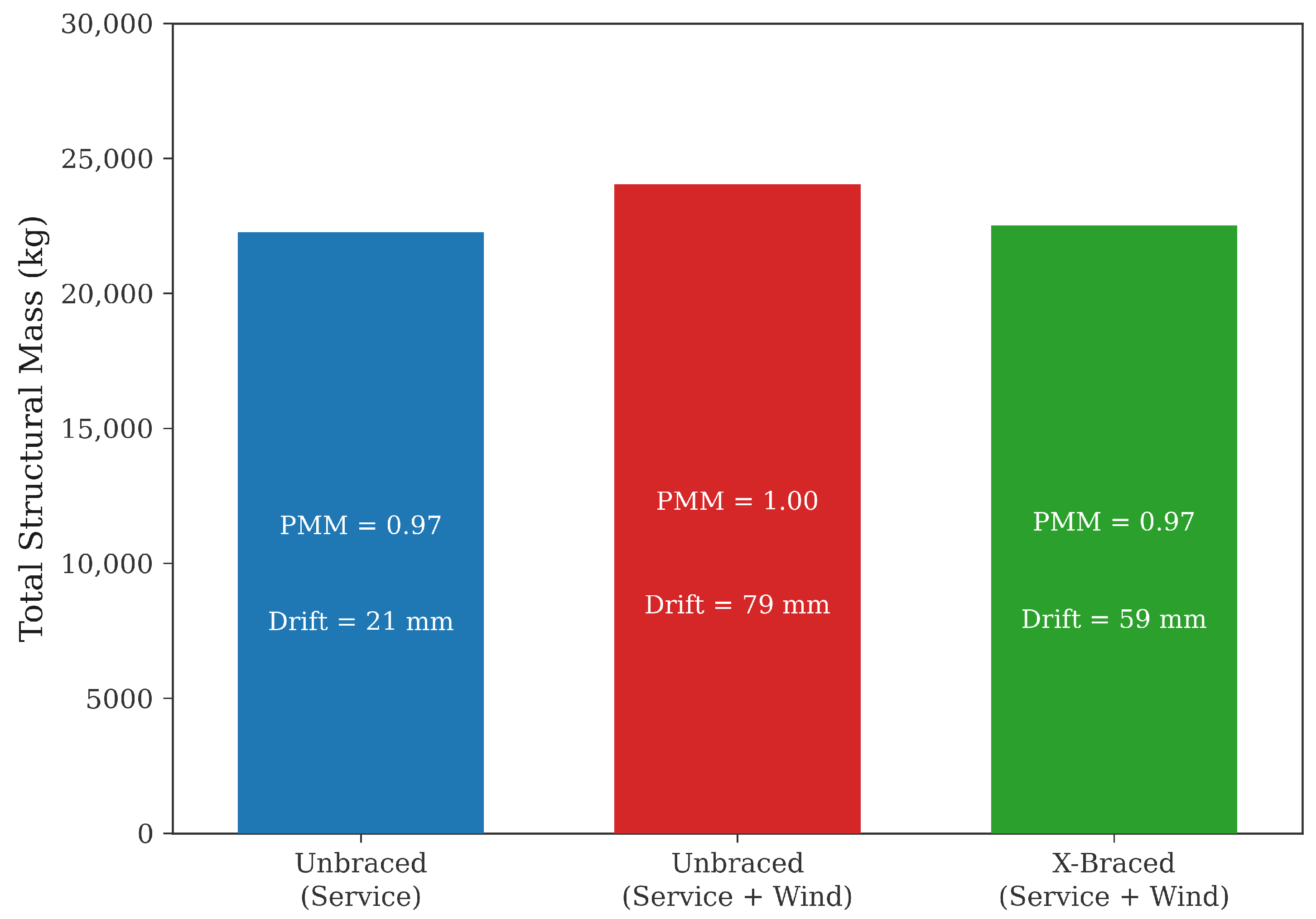
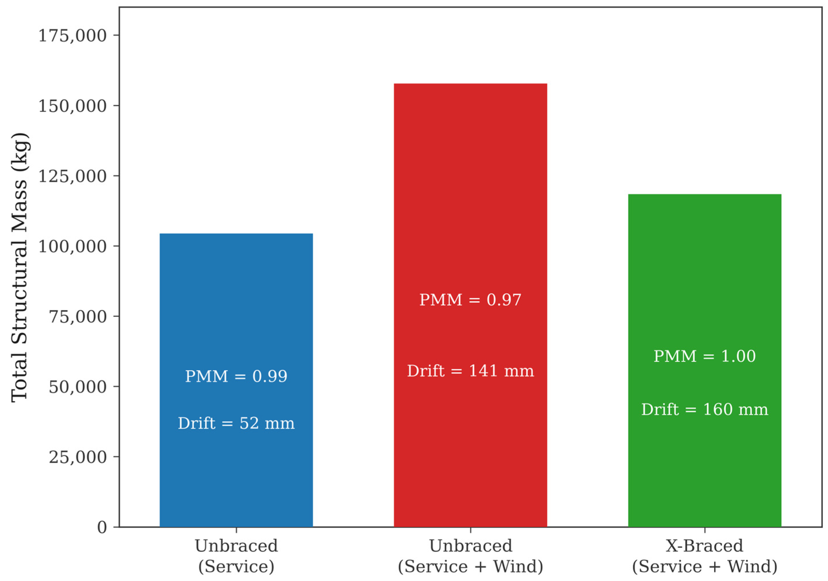
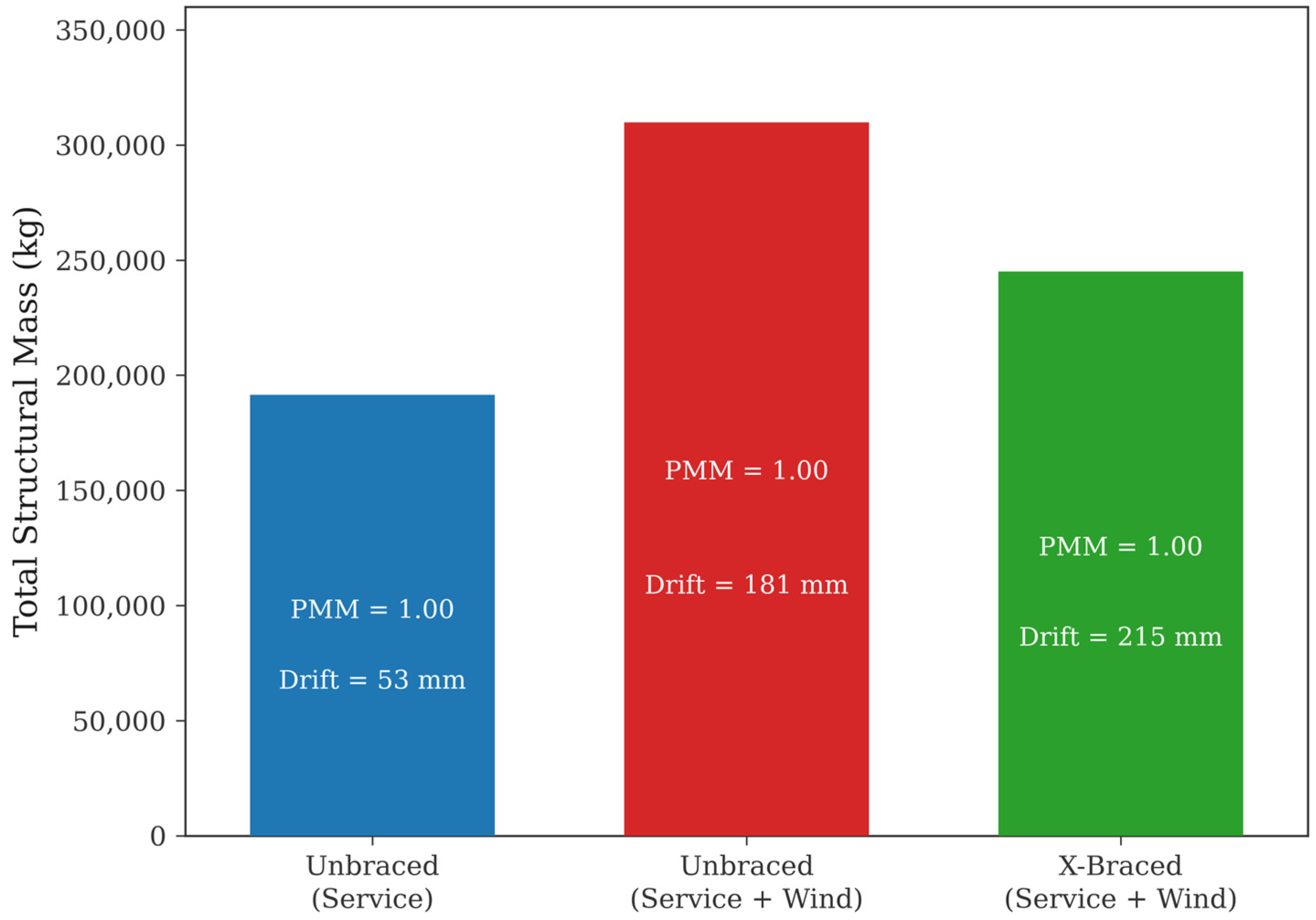
Figure 4 compares the optimized total structural mass of the 10-story frame for three study cases. The figure clearly shows that including wind loads increases the required structural mass in the unbraced frame, while the introduction of X-cable bracing reduces the total mass to a level close to that of the service-load-only case. This demonstrates the ability of cable bracing to offset the material demand introduced by wind loading in mid-rise frames. Figure 5 and Figure 6 present the same comparison for the 20-story and 30-story frames, respectively. In this case, the figure highlights a much larger increase in structural weight when wind loads are considered without bracing. The incorporation of X-cable bracing results in a significant decrease in overall weight, suggesting that the efficacy of bracing has a more pronounced effect on structures of greater height. The provided figure demonstrates that the impact of cable bracing on enhancing structural efficiency intensifies with increasing building height. Together, Figure 4, Figure 5 and Figure 6 visually emphasize the growing benefit of X-cable bracing with increasing building height, showing that cable bracing plays a more critical role in mitigating wind-induced weight penalties in taller frames.
Table 7 provides further insight by comparing the average interaction ratios across configurations. The average PMM is computed by taking the meaning of the interaction ratios across all beam and column elements. Interestingly, mean PMMs are larger in the braced cases compared to the unbraced cases. This suggests an increased overall member capacity mobilization by adding cable bracing. With the redistribution of lateral forces by the bracing system, a larger percentage of the frame members are actually participating in resisting forces. This explains why the average PMM is elevated in braced structures even though the maximum remains near unity. That is, higher average PMM in braced frames indicates that a larger proportion of members are more fully utilized, suggesting improved force redistribution.
For all configurations, these results show that wind-driven drift stayed within permissible amounts even though the interaction ratio seemed to be the determining variable in selecting member sizes. The addition of bracing not only reduced structural weight and drift but also promoted a more efficient distribution of internal forces across the structure, leading to more balanced utilization of the frame elements.

5. Conclusions Remarks

In this study, X-cable bracing systems were investigated to reduce the overall structural mass of high-rise steel structures with wind loading so that the requirements for strength and serviceability were achieved. Three numerical cases, namely 10-story, 20-story, and 30-story high-rise steel frame building, were optimized with Differential Evolution (DE) and Enhanced Colliding Bodies Optimization (ECBO) algorithms. Based on the results given here, the following were formulated:
  • Wind loading is a governing factor in tall steel building design. The inclusion of wind forces significantly increased the optimized structural weight compared to the gravity-only load cases.
  • The material demands caused by wind loads are lessened by cable bracing. Compared to the unbraced wind-loaded scenario, X-bracing decreased the overall weight and drift in the 10-story frame, 20-story frame, and 30-story frame by approximately 6%, 38%, and 34%, respectively.
  • In all design examples, strength, not drift, controlled the optimized designs. The maximum PMM ratios in all cases were at or near unity, indicating that member capacity governed section selection. Braced frames exhibited higher PMM ratios, suggesting that bracing redistributed lateral forces more evenly across members, leading to more balanced utilization of the structural system.
Future research could extend this work by incorporating dynamic wind effects, three-dimensional modeling, and experimental validation to broaden the applicability of the findings.

Author Contributions

Conceptualization, M.A.-B. and F.I.M.; methodology, S.J.A.-R.; software, M.A.-B.; validation, A.A.J., L.A. and M.M.A.; formal analysis, L.A.; investigation, A.A.J.; resources, F.I.M.; data curation, S.J.A.-R.; writing—original draft preparation, M.A.-B.; writing—review and editing, M.M.A.; visualization, S.J.A.-R.; supervision, M.A.-B.; project administration, L.A. All authors have read and agreed to the published version of the manuscript.

Funding

This research received no external funding.

Data Availability Statement

All code and datasets for this study are available from the corresponding author upon reasonable request.

Conflicts of Interest

No conflicts of interest are disclosed by the authors.

Nomenclature

AcronymDefinition
AISCAmerican Institute of Steel Construction
ASCEAmerican Society of Civil Engineers
ASTMAmerican Society for Testing and Materials
CBOColliding Bodies Optimization
DEDifferential Evolution
ECBOEnhanced Colliding Bodies Optimization
ELMEquivalent Linearization Method
FEAFinite Element Analysis
IBCInternational Building Code
OAPIOpen Application Programming Interface
PMMAxial Force–Bending Moment Interaction (P-M-M) Ratio
SAP2000Structural Analysis Program 2000
TBMRFTension-Braced Moment-Resisting Frame
SymbolDefinitionUnit
  V ( z ) Mean wind velocity at height zm/s
  V 10 Wind velocity at reference height 10 mm/s
  z Height above groundm
  α Power law exponent (terrain/atmospheric condition)
  q ( z ) Velocity pressure at height zN/m2
  ρ Air densitykg/m3
  F Wind force at a story levelkN
  P u Required axial strengthkN
  P n Nominal axial strengthkN
  M u y Required flexural strength about the y-axiskN·m
  M n y Nominal flexural strength about the y-axiskN·m
  ϕ Resistance factor (axial or flexure)
  Δ Lateral displacement at roof levelmm
  Δ max Allowable lateral displacementmm
  H Total building heightm
  M Total structural masskg
  X Design variable vector
  Obj ( X ) Merit (penalty) functionkg
  P ( X ) Constraint violation function
  ξ Penalty function exponent
  p κ Violation   value   of   the   κ -th constraint
  N M Total number of member groups
  N K Number   of   members   in   the   n k -th group
  m n m Mass   per   unit   length   of   members   in   the   n m -th groupkg/m
  L n k Length   of   the   n k -th memberm
  κ Constraint index
  K Total number of constraints

References

  1. Raju, K.R.; Shereef, M.; Iyer, N.R.; Gopalakrishnan, S. Analysis of tall building subjected to wind and seismic loads. In Proceedings of the National Conference of Emerging Technologies in Civil Engineering (ETC’13), Maharashtra, India, 12 April 2013. [Google Scholar]
  2. Fanaie, N.; Aghajani, S.; Afsar Dizaj, E. Strengthening of moment-resisting frame using cable–cylinder bracing. Adv. Struct. Eng. 2016, 19, 1736–1754. [Google Scholar] [CrossRef] [Scilit]
  3. Lotfollahi, M.; Alinia, M. Effect of tension bracing on the collapse mechanism of steel moment frames. J. Constr. Steel Res. 2009, 65, 2027–2039. [Google Scholar] [CrossRef] [Scilit]
  4. Saleem, M. Cable Bracing System for Tall Buildings. Pak. J. Sci. 2013, 65, 454–457. [Google Scholar]
  5. Jagadish, J.; Doshi, T.D. A study on bracing systems on high rise steel structures. Int. J. Eng. Res. Technol. 2013, 2, 1672–1676. [Google Scholar]
  6. Patil, S.J.; Mali, M.; Talikoti, R. Effect of wind load on high rise structure. Int. J. Recent Technol. Eng. 2015, 4, 2277–3878. [Google Scholar]
  7. Rajas, A.S.; Shelke, N. Wind analysis of high-rise building with different bracing systems. Int. J. Adv. Res. Sci. Eng. Technol. 2016, 3, 1923–1930. [Google Scholar]
  8. Alaghmandan, M.; Elnimeiri, M.; Krawczyk, R.J.; von Buelow, P. Modifying tall building form to reduce the along-wind effect. CTBUH J. 2016, 2, 34–39. [Google Scholar]
  9. Park, S.; Duthinh, D.; Simiu, E.; Yeo, D. Wind effects on a tall building with square cross-section and mid-side base columns: Database-assisted design approach. J. Struct. Eng. 2019, 145, 06019001. [Google Scholar] [CrossRef] [Scilit] [PubMed]
  10. Giaccu, G.F.; Caracoglia, L. A displacement-based approach for determining non-linear effects on pre-tensioned-cable cross-braced structures. J. Sound Vib. 2017, 394, 465–481. [Google Scholar] [CrossRef] [Scilit]
  11. Fanaie, N.; Zafari, N. Sensitivity analysis on response modification factor of new cable-cylinder bracing systems. J. Earthq. Eng. 2019, 23, 648–668. [Google Scholar] [CrossRef] [Scilit]
  12. Naghavi, M. Retrofitting steel moment frames by using the cable bracing. J. Build. Mater. Sci. 2020, 1, 10–17. [Google Scholar] [CrossRef] [Scilit]
  13. Rooshenas, A.; Barghian, M. Seismic behavior of cable braces strengthened with a central steel plate. Numer. Methods Civ. Eng. 2022, 6, 47–58. [Google Scholar] [CrossRef] [Scilit]
  14. Mosaddegh, I. Hysteretic Performance of Cable Bracing System with Central Steel Plate. TechRxiv 2025. [Google Scholar] [CrossRef] [Scilit]
  15. Taranath, B.S. Tall Building Design: Steel, Concrete, and Composite Systems; CRC Press: Boca Raton, FL, USA, 2016. [Google Scholar]
  16. AISC. Steel Construction Manual, 15th ed.; American Institute of Steel Construction: Chicago, IL, USA, 2017. [Google Scholar]
  17. ASCE7-22; Minimum Design Loads and Associated Criteria for Buildings and Other Structures. American Society of Civil Engineers (ASCE): Reston, VA, USA, 2022.
  18. Simiu, E.; Yeo, D. Wind Effects on Structures: Modern Structural Design for Wind; John Wiley & Sons: New York, NY, USA, 2019. [Google Scholar]
  19. Tieo, J.-J.; Skote, M.; Srikanth, N. Suitability of power-law extrapolation for wind speed estimation on a tropical island. J. Wind Eng. Ind. Aerodyn. 2020, 205, 104317. [Google Scholar] [CrossRef] [Scilit]
  20. West, M.; Fisher, A.; Griffis, L. Design Guide 3: Serviceability Design Considerations for Steel Buildings; AISC: Chicago, IL, USA, 2003. [Google Scholar]
  21. International Code Council. International Building Code 2000; Dearborn Trade Publishing: Chicago, IL, USA, 2000. [Google Scholar]
  22. Al-Bazoon, M.; Arora, J.S. Optimization of framed structures subjected to blast loading using equivalent static loads method. Asian J. Civ. Eng. 2023, 24, 3305–3318. [Google Scholar] [CrossRef] [Scilit]
  23. Weise, T. Global optimization algorithms-theory and application. Self-Publ. Thomas Weise 2009, 361, 153. [Google Scholar]
  24. Arora, J.S. Introduction to Optimum Design; Elsevier: Amsterdam, The Netherlands, 2004. [Google Scholar]
  25. Al-Bazoon, M. Harris Hawks Optimization for optimum design of truss structures with discrete variables. Int. J. Math. Eng. Manag. Sci. 2021, 6, 1157. [Google Scholar] [CrossRef] [Scilit]
  26. Al-Bazoon, M.; Arora, J.S. Discrete variable optimization of structures subjected to dynamic loads using equivalent static loads and metaheuristic algorithms. Optim. Eng. 2021, 23, 643–687. [Google Scholar] [CrossRef] [Scilit]
  27. Kaveh, A.; Mahdavi, V. Colliding bodies optimization: A novel meta-heuristic method. Comput. Struct. 2014, 139, 18–27. [Google Scholar] [CrossRef] [Scilit]
  28. Contreras-Bejarano, O.; Villalba-Morales, J.D.; Lopez-Garcia, D. Including problem-knowledge based modification into a Differential Evolution Algorithm for optimizing planar moment-resisting steel frames. Swarm Evol. Comput. 2025, 96, 101958. [Google Scholar] [CrossRef] [Scilit]
  29. Kaveh, A.; Zaerreza, A. Optimum design of the frame structures using the force method and three recently improved metaheuristic algorithms. Int. J. Optim. Civ. Eng. 2023, 13, 309–325. [Google Scholar]
  30. Safari, D.; Maheri, M.R.; Maheri, A. Optimum design of steel frames using different variants of differential evolution algorithm. Iran. J. Sci. Technol. Trans. Civ. Eng. 2021, 45, 2091–2105. [Google Scholar] [CrossRef] [Scilit]
  31. Shabakhty, N.; Motlagh, A.A.; Kaveh, A. Optimal design of offshore jacket platform using enhanced colliding bodies optimization algorithm. Mar. Struct. 2024, 97, 103640. [Google Scholar] [CrossRef] [Scilit]
  32. Ahmad, M.F.; Isa, N.A.M.; Lim, W.H.; Ang, K.M. Differential evolution: A recent review based on state-of-the-art works. Alex. Eng. J. 2022, 61, 3831–3872. [Google Scholar] [CrossRef] [Scilit]
  33. Storn, R.; Price, K. Differential evolution–a simple and efficient heuristic for global optimization over continuous spaces. J. Glob. Optim. 1997, 11, 341–359. [Google Scholar] [CrossRef] [Scilit]
  34. Eltaeib, T.; Mahmood, A. Differential evolution: A survey and analysis. Appl. Sci. 2018, 8, 1945. [Google Scholar] [CrossRef] [Scilit]
  35. Kaveh, A.; Ghazaan, M.I. Enhanced colliding bodies optimization for design problems with continuous and discrete variables. Adv. Eng. Softw. 2014, 77, 66–75. [Google Scholar] [CrossRef] [Scilit]
  36. Kaveh, A.; Kamalinejad, M.; Arzani, H.; Barzinpour, F. New enhanced colliding body optimization algorithm based on a novel strategy for exploration. J. Build. Eng. 2021, 43, 102553. [Google Scholar] [CrossRef] [Scilit]
Figure 1. Diagram showing 10-story 3-bay frame configuration (a) without bracing and (b) with bracing.
Constrmater 06 00026 g001
Figure 2. Diagram of 20-story 5-bay frame configuration (a) without bracing and (b) with bracing.
Constrmater 06 00026 g002
Figure 3. Diagram of 30-story 5-bay frame configuration (a) without bracing and (b) with bracing.
Constrmater 06 00026 g003
Figure 4. Structural mass with maximum PMM ratio and drift for the 10-story frame.
Constrmater 06 00026 g004
Figure 5. Structural mass with maximum PMM ratio and drift for the 20-story frame.
Constrmater 06 00026 g005
Figure 6. Structural mass with maximum PMM ratio and drift for the 20-story frame.
Constrmater 06 00026 g006
Table 1. Member properties.
MemberElement TypeMaterialSection or Diameter
Columns and beamsFrame elementASTM A992 Grade 50 steelAISC W-shapes [16]
BracingCable elementASTM A992 Grade 50 steel30 mm
Table 2. Wind speed, pressure, and panel force for five stories.
Storyz (m)V (m/s)q (N/m2)F (kN)
1422.09298.95298.95 × 6× 4 = 7.17
2826.27422.7810.15
31229.08517.8012.43
41631.24597.9014.35
52033.04668.4816.04
Table 3. Data for 10-story 3-bay frame designs.
Design VariablesService Loads OnlyService and Wind Load Without X-BracingService and Wind Load with X-Bracing
ECBODEECBODEECBODE
Run 1Run 2Run 1Run 2Run 1Run 2Run 1Run 2Run 1Run 2Run 1Run 2
BeamsW16X36W14X34W10X33W10X33W21X48W18X60W21X44W16X36W14X38W12X35W10X33W14X34
Columns 1W18X76W18X76W10X77W12X72W18X76W10X77W10X88W18X86W12X79W12X79W12X87W14X82
Columns 2W12X65W18X76W24X84W12X79W14X74W18X76W18X76W16X77W12X72W18X76W16X77W12X79
Columns 3W18X76W14X74W10X68W12X72W24X76W24X76W24X84W24X76W14X68W10X60W14X74W10X68
Columns 4W12X53W12X65W27X84W16X67W14X68W24X68W14X68W21X73W10X54W14X68W12X58W12X65
Columns 5W21X62W21X62W12X58W14X61W18X65W12X58W21X73W14X61W12X58W21X62W8X67W12X58
Columns 6W16X67W12X50W24X68W18X60W12X50W10X49W14X48W14X61W12X50W18X65W10X49W14X68
Columns 7W21X55W12X79W12X65W21X48W21X48W21X62W21X62W8X58W18X50W18X60W8X48W16X57
Columns 8W24X55W8X35W8X40W14X43W16X40W21X48W21X48W8X40W14X38W16X40W12X50W10X39
Columns 9W16X67W10X68W8X24W8X28W10X33W24X76W18X46W8X35W14X38W12X40W14X30W14X34
Columns 10W18X71W10X77W10X45W14X53W16X67W27X84W21X44W18X60W12X79W10X33W16X77W14X82
Total mass (kg)24,21523,84623,15022,24526,62031,54926,95424,00122,96523,30522,48323,370
Max. PMM ratio1.00 (C4)1.00 (C4)0.99 (C9)0.97 (C1)0.99 (C5)1.00 (C4)0.99 (C6)1.00 (C3)0.99 (C9)0.99 (C3)0.97 (B1)0.98 (C1)
Max. drift (mm)20 (D)20 (D)20 (D)21 (D)65 (W)78 (W)79 (W)79 (W)50 (W)52 (W)59 (W)50 (W)
C = Column; B = beam; number = story level (e.g., C1 = 1st story column, B1 = 1st story beam); D = dead load case; W = wind load case.
Table 4. Data for 20-story 5-bay frame designs.
Design VariablesService Loads OnlyService and Wind Load Without BracingService and Wind Load with X-Bracing
ECBODEECBODEECBODE
Run 1Run 2Run 1Run 2Run 1Run 2Run 1Run 2Run 1Run 2Run 1Run 2
BeamsW16X45W16X45W12X45W12X45W27X114W30X90W30X90W30X90W21X55W27X94W24X55W24X55
Columns 1 and 2W14X132W14X145W27X146W27X146W14X145W14X145W27X146W27X146W14X145W14X145W14X145W14X145
Columns 3 and 4W18X143W14X120W21X132W21X132W14X132W36X150W36X150W36X150W12X136W27X146W36X150W36X150
Columns 5 and 6W24X117W18X119W14X120W14X109W24X146W18X130W21X122W27X146W18X119W33X141W36X135W30X148
Columns 7 and 8W14X99W18X119W14X120W14X120W30X124W27X129W18X130W30X124W24X104W36X135W33X141W33X118
Columns 9 and 10W14X99W12X106W27X114W18X97W30X116W21X101W18X130W30X116W33X130W30X116W18X106W27X102
Columns 11 and 12W12X72W10X77W27X102W12X96W24X94W18X130W14X99W24X104W27X94W27X94W10X77W18X76
Columns 13 and 14W10X77W10X77W12X65W14X68W30X90W30X132W21X93W30X90W12X79W21X83W14X61W10X77
Columns 15 and 16W12X65W8X58W21X68W24X76W24X103W12X120W24X84W14X61W18X71W24X68W30X90W10X49
Columns 17 and 18W16X45W12X45W14X48W18X55W21X55W24X103W18X65W21X55W16X57W40X149W24X55W21X48
Columns 19 and 20W14X132W27X146W24X55W16X50W16X45W16X67W18X60W14X53W18X46W16X45W14X145W14X120
Total mass (kg)104,255105,255108,755107,612181,722168,222159,578157,650119,827167,579124,827118,255
Max. PMM ratio0.99 (C1)1.00 (C5)0.97 (C3)0.97 (C5)0.98 (C1)0.99 (C1)0.98 (C3)0.97 (C3)1.00 (C1)0.94 (C1)1.00 (C13)1.00 (C1)
Max. drift (mm)52 (D)51 (D)50 (D)50 (D)119 (W)156 (W)149 (W)141 (W)134 (W)99 (W)131 (W)160 (W)
C = Column; number = story level (e.g., C5 = 5th story column); D = dead load case; W = wind load case.
Table 5. Data for 30-story 5-bay frame designs.
Design VariablesService Loads OnlyService and Wind Load Without BracingService and Wind Load with X-Bracing
ECBODEECBODEECBODE
BeamsW21X50W21X50W21X50W14X38W27X102W24X103W24X104W14X233W30X90W36X231W27X84W21X83
Columns 1 and 3W24X207W14X159W24X229W14X211W27X235W30X235W27X235W27X194W33X241W27X194W30X235W21X182
Columns 4 and 6W12X190W14X145W12X190W18X211W21X201W27X194W40X199W14X193W30X191W36X194W30X191W30X173
Columns 7 and 9W12X170W14X145W12X170W24X176W27X161W24X176W27X161W18X175W21X182W14X176W21X182W30X235
Columns 10 and 12W12X152W12X210W24X162W40X215W24X192W36X182W36X182W18X158W24X162W14X176W27X161W27X178
Columns 13 and 15W27X146W33X141W18X130W18X158W14X145W40X215W18X143W18X130W12X136W12X136W12X136W18X234
Columns 16 and 18W14X109W18X106W18X119W36X150W40X235W36X232W36X232W18X119W18X119W24X104W18X119W18X130
Columns 19 and 21W12X96W12X87W24X104W14X99W24X131W36X194W36X135W27X129W10X100W12X87W14X99W33X152
Columns 22 and 24W27X84W16X100W10X100W27X84W33X141W24X103W36X135W14X90W24X104W10X68W10X88W36X194
Columns 25 and 27W27X94W10X17W24X104W30X124W18X71W30X90W16X67W8X40W24X84W21X93W16X77W40X211
Columns 28 and 30W18X55W27X217W14X74W21X101W24X55W14X53W16X50W27X114W8X40W24X68W14X48W12X79
Total mass (kg)206,045191,258212,474207,974309,549322,674309,977317,157271,512244,725259,511301,030
Max. PMM ratio0.99 (C1)1.00 (C5)0.97 (C3)0.97 (C5)1.00 (C1)0.99 (C4)1.00 (C7)0.99 (C3)0.99 (C1)1.00 (C3)1.00 (C13)0.98 (C1)
Max. drift (mm)50 (D)53 (D)61 (D)56 (D)181 (W)161 (W)104 (W)202 (W)150 (W)215 (W)221 (W)145 (W)
C = Column; number = story level (e.g., C5 = 5th story column); D = dead load case; W = wind load case.
Table 6. Effect of wind load and X-cable bracing on structural weight.
Frame TypeCaseMass (kg)% Change Relative to the Unbraced Structure Subject to Service Load Only
10-StoryUnbraced (service)22,245-
Unbraced (service + wind)24,001+7.9%
X-braced (service + wind)22,483+1.1%
20-StoryUnbraced (service)104,255-
Unbraced (service + wind)157,650+51.2%
X-braced (service + wind)118,255+13.4%
30-StoryUnbraced (service)191,258-
Unbraced (service + wind)309,54961.9%
X-braced (service + wind)244,72527.9%
Table 7. Comparison of the interaction ratio.
Frame TypeCaseMaximum PMMAverage PMM
10-StoryUnbraced (service)0.970.761
Unbraced (service + wind)1.000.673
X-braced (service + wind)0.980.746
20-StoryUnbraced (service)0.990.626
Unbraced (service + wind)0.970.531
X-braced (service + wind)1.000.681
30-StoryUnbraced (service)1.000.816
Unbraced (service + wind)1.000.721
X-braced (service + wind)1.000.801
Disclaimer/Publisher’s Note: The statements, opinions and data contained in all publications are solely those of the individual author(s) and contributor(s) and not of MDPI and/or the editor(s). MDPI and/or the editor(s) disclaim responsibility for any injury to people or property resulting from any ideas, methods, instructions or products referred to in the content.