Article

Enhanced Na+ Transport in Cu-MOF Reinforced PEO Solid-State Polymer Electrolyte for High-Rate Sodium Metal Batteries


School of Materials Science and Engineering, Central South University, Changsha 410083, China
*
Author to whom correspondence should be addressed.
Nanoenergy Adv. 2026, 6(3), 23; https://doi.org/10.3390/nanoenergyadv6030023
Submission received: 14 June 2026 / Revised: 14 July 2026 / Accepted: 22 July 2026 / Published: 28 July 2026

Abstract

Poly(ethylene oxide) (PEO)-based solid polymer electrolytes are regarded as highly promising solid electrolyte materials owing to their favorable chain flexibility. However, their practical application is hindered by low room-temperature ionic conductivity and poor mechanical properties. To address these issues, a metal–organic framework (Cu-MOF) with a 2D layered structure and 1D microchannels is introduced into PEO to form a composite solid electrolyte. The results reveal that Cu-MOF can suppress PEO crystallization through steric hindrance and coordination interactions, thereby increasing the fraction of the amorphous phase. Moreover, its unsaturated metal sites can attract TFSI anions, promoting the dissociation of the sodium salt and enhancing sodium-ion transport. Theoretical calculations and molecular simulations further confirm the regulatory role of Cu-MOF in ion transport. Leveraging this mechanism, the Na3V2(PO4)3/C|PCM-8%|Na cell delivers exceptional electrochemical performance over a wide temperature range. At room temperature, the capacity exhibits virtually no decay after 200 cycles at 0.5 C, and outstanding rate capability is maintained even at a high rate of 4 C. At a temperature of 65 °C, a capacity retention of 91.4% is achieved after 200 cycles at 0.5 C. This study offers a highly promising strategy for the development of wide-temperature-range, high-performance solid-state sodium batteries.

1. Introduction

All-solid-state sodium metal batteries have shown great promise in achieving higher energy density and enhanced safety by replacing conventional organic liquid electrolytes with solid electrolytes [1]. Solid Polymer Electrolytes (SPEs) have attracted extensive attention due to their good processability and favorable interfacial compatibility [2]. Among them, poly(ethylene oxide) (PEO)-based solid polymer electrolytes are regarded as highly promising solid electrolyte materials owing to their high safety and stability, excellent chain flexibility, good electrochemical stability, and favorable solubility with conductive sodium salts [3]. The ion transport mechanism of PEO involves the continuous complexation and dissociation of Ethylene Oxide (EO) monomers with sodium ions under the influence of an electric field, thereby facilitating the transport of sodium ions [4]. However, its application is limited by high crystallinity and low room-temperature ionic conductivity, as well as poor mechanical properties that readily lead to dendrite growth and subsequent battery short-circuiting [5,6,7]. To overcome these limitations of PEO, the ionic transport rate can be enhanced by introducing other polymer segments to crosslink with PEO, constructing a three-dimensional network [8]. The addition of plasticizers (e.g., succinonitrile [9]) or ionic liquids (e.g., Pyr13FSI [10,11]) can improve polymer chain dynamics and thereby accelerate ion transport, but this often compromises mechanical properties and results in poor cycling stability.
Incorporating fillers into PEO to fabricate composite polymer solid electrolytes is an effective strategy for enhancing ionic conductivity and mechanical properties [4]. In contrast to the simple physical blending effect of conventional ceramic fillers, metal–organic frameworks (MOFs) possess unique pore structures and metal active sites, thereby combining the functions of ion channels and chemical anchoring. Moreover, their pore architecture, size, and shape can be precisely tailored by varying the types of ligands and synthesis conditions to meet the requirements of different ion carriers [12]. These materials, supported by a porous framework, regulate ion transport through abundant active sites, while simultaneously achieving high mechanical strength and high thermal stability. Furthermore, they offer significant advantages in broadening the electrochemical window, making them an ideal choice for application in solid-state sodium metal batteries [13]. For instance, Zhang et al. [14] fabricated a solid-state electrolyte, denoted as PLM, using pancake-shaped MIL-125. The unique morphology of this MOF endows PLM with a higher specific surface area and facilitates rapid migration of sodium ions, achieving a high ionic conductivity of 6.60 × 10⁻⁴ S cm−1 and a sodium ion transference number of 0.33 at room temperature. The assembled full cell achieved a specific capacity retention of 88% after 160 cycles at a current density of 100 mA g−1. Furthermore, Zhang et al. [15] developed a flexible MOF-based solid electrolyte (Na/Mg-MOF-74). The introduction of Mg-MOF-74 effectively immobilizes anions, thereby enhancing ionic conductivity. This electrolyte exhibits a high ionic conductivity of 3.48 × 10⁻⁴ S cm−1 at 25 °C. Owing to the outstanding performance of the electrolyte, the battery assembled with a Na metal anode and a Na3V2(PO4)3 cathode delivers exceptional electrochemical performance, with an initial discharge specific capacity of 59.66 mAh g−1 at 1 C and a capacity retention of 81% after 100 cycles, demonstrating excellent long-term cyclability.
The advantages of MOF-based fillers depend on their morphology, pore size, and open metal sites (OMS) [16]. Among these, an ideal pore size should match the migrating ions (e.g., sodium ions) to achieve rapid transport, while the concentration of OMS directly determines the ability of MOFs to regulate ionic conduction. For instance, Materials of Institute Lavoisier-53 (MIL-53) has coordinatively saturated Al metal sites and lacks OMS, making it difficult to effectively promote sodium ion conduction [13]. In contrast, Cu-MOF possesses abundant OMS, which can accelerate the dissociation of sodium salts and facilitate the migration of sodium ions [17]. Therefore, Cu-MOF materials synthesized from copper ions and organic carboxylic acid ligands are gradually becoming a research hotspot in this field. Tian et al. [18] introduced three-dimensional (3D) HKUST-1 supported on polyacrylonitrile (PAN) fibers into a PEO-based solid polymer to construct a composite electrolyte (denoted as PPNM), leveraging the properties of the Cu-MOF and PAN to enhance Na+ transport. The Cu-MOF promotes the formation of inorganic-rich (NaF and Na3N) cathode–electrolyte interphase (CEI) and solid–electrolyte interphase (SEI) by attracting TFSI anions, thereby contributing to interfacial stability.
Notably, the structure of Cu-MOF varies significantly depending on the ligand used. Han et al. [19] systematically investigated the morphological characteristics and crystal growth behavior of several typical Cu-MOFs synthesized with different ligands. However, in contrast to the three-dimensional HKUST-1 synthesized with trimesic acid as the ligand, which possesses tortuous pore channels, the Cu-MOF synthesized with terephthalic acid exhibits a two-dimensional layered structure. Its internal one-dimensional microporous channels impose lower resistance to ion migration, and the layered structure increases the interfacial contact area, constructing a more continuous ion transport network and demonstrating superior interfacial flexibility [20,21]. Although common MOF materials such as HKUST-1 or Cu-MOF-74 have been employed as fillers to improve PEO-based solid-state electrolytes (SCEs), the interaction mechanism between the Cu-MOF synthesized with terephthalic acid and PEO remains poorly understood, and in-depth investigations are still lacking [17,18].
Based on this, we prepared a solid-state electrolyte by compositing Cu-MOF synthesized with terephthalic acid with PEO, and systematically investigated the effect of Cu-MOF doping concentrations (4 wt%, 8 wt%, 12 wt%) on the performance of the solid-state electrolyte, aiming to elucidate the underlying mechanism by which Cu-MOF enhances PEO segmental motion and reduces the energy barrier for ion migration. Electrochemical tests and theoretical calculations demonstrate that the incorporation of Cu-MOF suppresses the crystallization of PEO and increases the proportion of amorphous regions. Meanwhile, Cu-MOF attracts TFSI anions through its open unsaturated metal active sites, promoting the dissociation of sodium salts and significantly enhancing sodium ion transport. Furthermore, the two-dimensional layered structure and one-dimensional microporous channels of Cu-MOF further reduce the migration resistance of sodium ions. This synergistic mechanism endows the prepared solid-state electrolyte with excellent ionic conductivity and cycling stability over a wide temperature range. The assembled Na3V2(PO4)3/C|PCM-8%|Na battery delivered a discharge specific capacity of 85.23 mAh g−1 after 200 cycles at 0.5 C at room temperature, with virtually no capacity decay. At a moderately elevated temperature of 65 °C under the same rate, the capacity reached 99.42 mAh g−1 after 200 cycles, corresponding to a capacity retention of 91.4%. This work opens up a new pathway for the practical application of MOF-doped high-performance polymer solid electrolytes over a wide temperature range.

2. Materials and Methods

2.1. Materials

Copper-based metal–organic framework (Cu-MOF) material was prepared using terephthalic acid (H2BDC, 99%, Aladdin, Shanghai, China), Copper(II) Nitrate Trihydrate (Cu(NO3)2·3H2O, AR, Sinopharm Co., Ltd., Beijing, China), and N,N-dimethylformamide (DMF, AR, Sinopharm Co., Ltd.). The solid-state electrolyte membrane was fabricated using poly(ethylene oxide) (PEO, molecular weight = 600,000 g·mol−1, Aladdin), anhydrous acetonitrile (ACN, AR, Sinopharm Co., Ltd.), and sodium bis(trifluoromethanesulfonyl)imide (NaTFSI, 99.99%, DoDoChem, Suzhou, China). The cathode material was prepared using Na3V2(PO4)3/C (NVP/C, DoDoChem), N-methyl-2-pyrrolidone (NMP, AR, Sinopharm Co., Ltd.), and poly(vinylidene fluoride) (PVDF, Canrd Technology Co., Ltd., Dongguan, China).

2.2. Preparation of Cu-MOF

First, 0.4832 g of Cu(NO3)2·3H2O was precisely weighed according to the corresponding proportion and dissolved in 50 mL of a mixed solution (DMF:EtOH = 1:1). Then, 0.3356 g of H2BDC was dissolved in 50 mL of DMF solution. The mixed solution of Cu(NO3)2·3H2O was slowly added to the H2BDC solution. After ultrasonication for 20 minutes to ensure homogeneous mixing of the reaction system, the resulting solution was transferred into a high-pressure autoclave for hydrothermal reaction at 120 °C for 12 h. After the reaction system was cooled to room temperature, the product was collected by suction filtration and washed repeatedly with DMF and anhydrous methanol in sequence. The obtained product was then dried under vacuum at 120 °C for 12 h, yielding the final product designated as Cu-MOF.

2.3. Preparation of Cu-MOF Composite PEO-Based Solid-State Electrolyte

In this study, Cu-MOF composite PEO-based solid-state electrolyte membranes (denoted as PCM) were prepared using the solution casting method. Specifically, the PEO matrix solution was prepared at a fixed EO:Na molar ratio of 18:1 by adding 1.75 g of PEO and 0.67 g of NaTFSI to 25 mL of acetonitrile. Subsequently, varying amounts of Cu-MOF (4 wt%, 8 wt%, and 12 wt%) were introduced into the PEO matrix solution. The mixture was stirred at room temperature for 12 h to ensure homogeneity, then cast onto a polytetrafluoroethylene (PTFE) mold. The cast membrane was dried at room temperature under N2 atmosphere for 6 h to remove most of the acetonitrile solvent, followed by further drying at 60 °C in a glovebox for 48 h to eliminate residual acetonitrile. The resulting Cu-MOF composite solid polymer electrolyte membranes with different filler contents were designated as PCM-4%, PCM-8%, and PCM-12%, respectively. The membranes were then cut into discs with a diameter of 16 mm and stored in a glovebox for subsequent use. For comparison, a PEO/NaTFSI solid electrolyte without Cu-MOF was also prepared under the same conditions and designated as PEO.

2.4. Preparation of the Cathode Material Na3V2(PO4)/C (NVP/C)

The cathode was prepared by mixing the active material Na3V2(PO4)3/C, acetylene black, and poly(vinylidene fluoride) (PVDF) at a mass ratio of 8:1:1. The mixture was then dissolved in NMP, and after homogeneous mixing, the resulting slurry was coated onto aluminum foil and dried in a vacuum oven at 70 °C for 12 h for subsequent use. The dried electrode sheet was punched into circular disks with a diameter of 12 mm using a punching machine, and the active material loading on the resulting cathode disks was in the range of 1.5–3.0 mg·cm−2.

2.5. Structural Characterization

The influence of Cu-MOF on the crystallinity of PCM solid-state electrolytes was analyzed by X-ray diffraction (XRD, SMARTLAB 3 kW, RIGAKU, Akishima, Tokyo, Japan) over a scan range of 5° to 50° at a scan rate of 6°·min−1. All XRD patterns of the PEO and PCM solid-state electrolytes are presented without normalization. All measurements were conducted under identical conditions to allow relative comparison of peak intensities. The surface morphology of the PCM solid-state electrolyte materials was observed using scanning electron microscopy (SEM, TESCAN MIRA3, TESCAN, Brno, Czech Republic). Given that the morphology at low MOF loading (e.g., 4%) resembles that of the neat PEO matrix, whereas high loading (e.g., 12%) tends to induce agglomeration, the PCM-8% sample, which adequately captures the uniform dispersion and favorable interfacial compatibility of the MOF, was selected along with pristine PEO for morphological analysis. The specific surface area and pore size distribution of Cu-MOF were analyzed by nitrogen adsorption–desorption measurements (BET, Kubo X1000, Beijing, China), and the structure was analyzed by high-resolution transmission electron microscopy (HRTEM, TECNAI F2, FEI, Hillsboro, OR, USA). Prior to the measurements, the samples were dried and degassed to enable effective adsorption or pore filling. The intermolecular interactions within the Cu-MOF composite PEO system were analyzed by Fourier-transform infrared spectroscopy (FTIR, VERTEX 70, BRUKER, Ettlingen, Germany) and Raman spectroscopy (Horiba JY LabRAM HR, Longjumeau, France). The spectral resolution of the FTIR measurement was 2 cm−1. The elemental valence states were characterized by X-ray photoelectron spectroscopy (XPS) using a K-Alpha spectrometer (Thermo Fisher Scientific, East Grinstead, UK). The PCM-8% sample, featuring uniform MOF dispersion, was selected for FTIR, Raman, and XPS analyses. Its spectral data effectively reveal the chemical interactions between the MOF and PEO, and the results were compared with those obtained from pristine PEO. The thermal stability of the materials was analyzed by thermogravimetric analysis (TGA, NETZSCH, TGA 209 F1, Selb, Germany) under N2 atmosphere at a heating rate of 10 °C min−1 over a temperature range of 30–600 °C. The crystallization behavior of PEO in the materials was analyzed by differential scanning calorimetry (DSC, TA Q200, New Castle, DE, USA). The measurements were performed under N2 atmosphere at a heating rate of 10 °C·min−1 as follows: heating from room temperature to 100 °C, then cooling to −80 °C, followed by reheating to 100 °C. After eliminating thermal history, the second heating curve was used for characterization. The mechanical properties of the solid-state electrolyte membranes were tested using a universal material testing machine (HDW-20, Jinan, China).

2.6. Electrochemical Characterization

Electrochemical performance was evaluated using assembled CR2032 coin-type cells (NEWARE) in an argon-filled glovebox with H2O and O2 levels maintained below 0.1 ppm.
(1) Stainless steel symmetric cells with an SS|SPEs|SS configuration were assembled, and the ionic conductivity at various temperatures was measured by electrochemical impedance spectroscopy (EIS) over a frequency range of 100–106 Hz. The ionic conductivity was calculated according to the following equation:
σ = L S R t
where σ is the ionic conductivity of the solid-state electrolyte (S cm−1), and L denotes the average thickness (cm) determined from multiple measurements. Rt is the resistance of the solid-state electrolyte (Ω). The resistance of each electrolyte membrane was obtained from the high-frequency intercept of the impedance spectra. S is the area of the solid-state electrolyte (cm2).
In addition, the ionic conductivity was measured at various temperatures, and the activation energy (Ea) was calculated using the Arrhenius equation, which is expressed as follows:
σ = σ 0 exp E a k B T
where σ is the ionic conductivity at a given temperature, σ0 is the pre-exponential factor, Ea is the activation energy, kB is the Boltzmann constant (1.380649 × 10⁻²³ J K−1), and T is the absolute temperature (K). By plotting Log(σ) versus 1000/T and performing a linear fit, the value of Ea was determined from the slope of the fitted line.
(2) Na|SPEs|SS cells were assembled, and the electrochemical stability window of the electrolyte membrane was evaluated by linear sweep voltammetry (LSV) over a potential range of 2.5–8 V at a scan rate of 1 mV s−1. Both LSV and electrochemical impedance spectroscopy (EIS) measurements were performed on an electrochemical workstation (CHI 760E, CH Instruments, Inc., Austin, TX, USA).
(3) Symmetric cells with a Na|SPEs|Na configuration were assembled to determine the sodium-ion transference number (tNa+). The impedance was measured before and after polarization under an applied potential of 10 mV, and tNa+ was calculated using the following equation:
t N a + = I S V I 0 R 0 I 0 V I S R S
where tNa+ is the sodium-ion transference number of the electrolyte, I0 is the initial current at the onset of polarization, IS is the steady-state current, R0 is the initial interfacial resistance of the electrolyte, RS is the interfacial resistance after polarization, and ΔV is the applied polarization voltage (10 mV).
(4) Cells with an NVP/C|SPEs|Na configuration were assembled for electrochemical testing, in which metallic sodium foil (purity 99.9%, thickness 0.6 mm, KOLUD) was used as the anode and NVP/C was employed as the cathode. Galvanostatic cycling tests were conducted using a Neware battery testing system (CT-4008T, NEWARE, Shenzhen, China) within a voltage range of 2.0–4.0 V. The theoretical specific capacity of the NVP/C cathode was set to 115 mAh·g−1. Prior to cycling, the cells were allowed to rest for 6 h to stabilize the electrode/electrolyte interface. Electrochemical measurements were carried out at 65 °C and at room temperature (RT, 26 ± 2 °C), respectively. For the room-temperature tests, 1 μL of liquid electrolyte was added dropwise onto the cathode side to optimize interfacial contact.

2.7. Density Functional Theory Calculation and Molecular Dynamic Simulations

The DMol3 program within BIOVIA Materials Studio 2023 was employed for all density functional theory (DFT) calculations. Electron exchange and correlation effects were treated using the generalized gradient approximation (GGA) with the Perdew–Burke–Ernzerhof (PBE) functional. All atoms in the system were described by a double numerical plus polarization (DNP) basis set, while core electrons were handled with density functional semi-core pseudopotentials (DSPP). The convergence criteria for geometry optimization were set to 1.0 × 10⁻⁵ Ha for energy, 0.002 Ha Å−1 for maximum force, and 0.005 Å for maximum displacement.
The Forcite module within BIOVIA Materials Studio 2023 was employed for all molecular dynamics (MD) simulations. The PEO system consisted of 9 PEO chains each containing 100 monomer units, 50 Na+, and 50 TFSI, yielding an EO:Na ratio of 18:1. For the PCM-8% system, 12 Cu2+ and 24 BDC molecules were additionally introduced. After assigning force field parameters, all MD simulations were performed with periodic boundary conditions in three dimensions. Long-range electrostatics were treated by the Ewald method. The total energy comprised bonded (including diagonal and off-diagonal cross-coupling terms) and non-bonded contributions described by Coulombic and Lennard-Jones functions, with pairwise parameters taken from the COMPASS force field. The initial configurations were energy-minimized using the Smart Minimizer method, followed by approximately 3 ns NPT equilibration (1 fs time step, 298.15 K, 1 bar); coordinates were saved every 5 ps.

3. Result and Discussion

3.1. Morphology Characterization

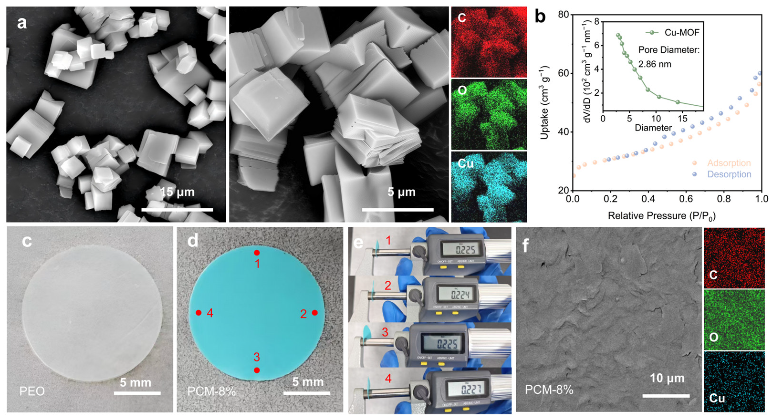
In this study, a Cu-MOF material synthesized via a hydrothermal method using terephthalic acid as the ligand was introduced (Figure S1). The microstructure of the Cu-MOF significantly influences the ion transport properties of the electrolyte. To this end, the morphology of the Cu-MOF was first examined by scanning electron microscopy (SEM). As shown in Figure 1a, the Cu-MOF exhibits a well-defined two-dimensional square-shaped layered block-like morphology. The corresponding EDS elemental mapping reveals a homogeneous distribution of Cu, C, and O throughout the structure. Subsequently, (Figure S2) high-resolution transmission electron microscopy (HRTEM) reveals clear lattice fringes with a spacing of 0.184 nm, which may correspond to the (−603) plane of Cu-MOF. This plane is the third-order diffraction plane of the preferentially oriented (−201) growth plane [19]. In addition, the specific surface area and pore size distribution were analyzed by N2 adsorption–desorption measurements (BET). The N2 adsorption–desorption isotherm (Figure 1b) reveals that the synthesized Cu-MOF possesses a specific surface area of 100.31 m2 g−1 and an average pore size of 2.86 nm. The porous structure provides abundant adsorption sites on the surface, and the pore dimensions are sufficiently large to accommodate the passage of numerous Na+.
Subsequently, Cu-MOF was compounded with PEO and sodium bis(trifluoromethanesulfonyl)imide (NaTFSI) at different doping ratios (4 wt%, 8 wt%, 12 wt%) to prepare solid-state electrolyte membranes, which were denoted as PCM-4%, PCM-8%, and PCM-12%, respectively. The control group without Cu-MOF was designated as PEO. The as-prepared PEO and PCM-8% solid-state electrolytes are shown in Figure 1c,d. It can be observed that Cu-MOF nanoparticles are uniformly dispersed within the PEO matrix, with no significant large-scale agglomeration. To minimize measurement errors, the thickness was measured at multiple positions (Figure 1e). The average thickness of the synthesized PCM-8% solid electrolyte membrane was determined to be 225 µm. The microstructure of the solid-state electrolytes was further examined by scanning electron microscopy (Figure 1f and Figure S3). In the SEM images, the surface of PEO appears rough with numerous dendritic patterns. In contrast, the surface of PCM-8% exhibits a relatively flat morphology. These observations are attributed to the incorporation of Cu-MOF, which suppresses the crystallization of PEO, thereby reducing the crystalline dendritic features and leading to the formation of a more uniform and dense electrolyte membrane [22]. In addition, the EDS elemental mapping of the PCM-8% membrane reveals a homogeneous distribution of Cu, C, and O throughout the structure, further confirming that the Cu-MOF fillers are well dispersed within the composite membrane without significant large-scale agglomeration.

3.2. Structural and Physicochemical Characterization

The suppression of PEO crystallization by Cu-MOF arises from two aspects. The first is the steric hindrance effect, wherein Cu-MOF, as a porous nanofiller dispersed in PEO, hinders the migration and ordered arrangement of PEO chain segments, thereby increasing the amorphous regions that are favorable for ion conduction. The second is the coordination effect, wherein the open metal sites of Cu2+ interact with the ether oxygen bonds of PEO via coordination, constraining the PEO chains and reducing their orderliness [18]. These two effects work synergistically to effectively reduce the crystallinity of PEO and promote the migration of sodium ions. To systematically elucidate the above mechanism, this work conducted an in-depth analysis of the Cu-MOF and its composite solid-state electrolyte membranes using multiple characterization techniques.
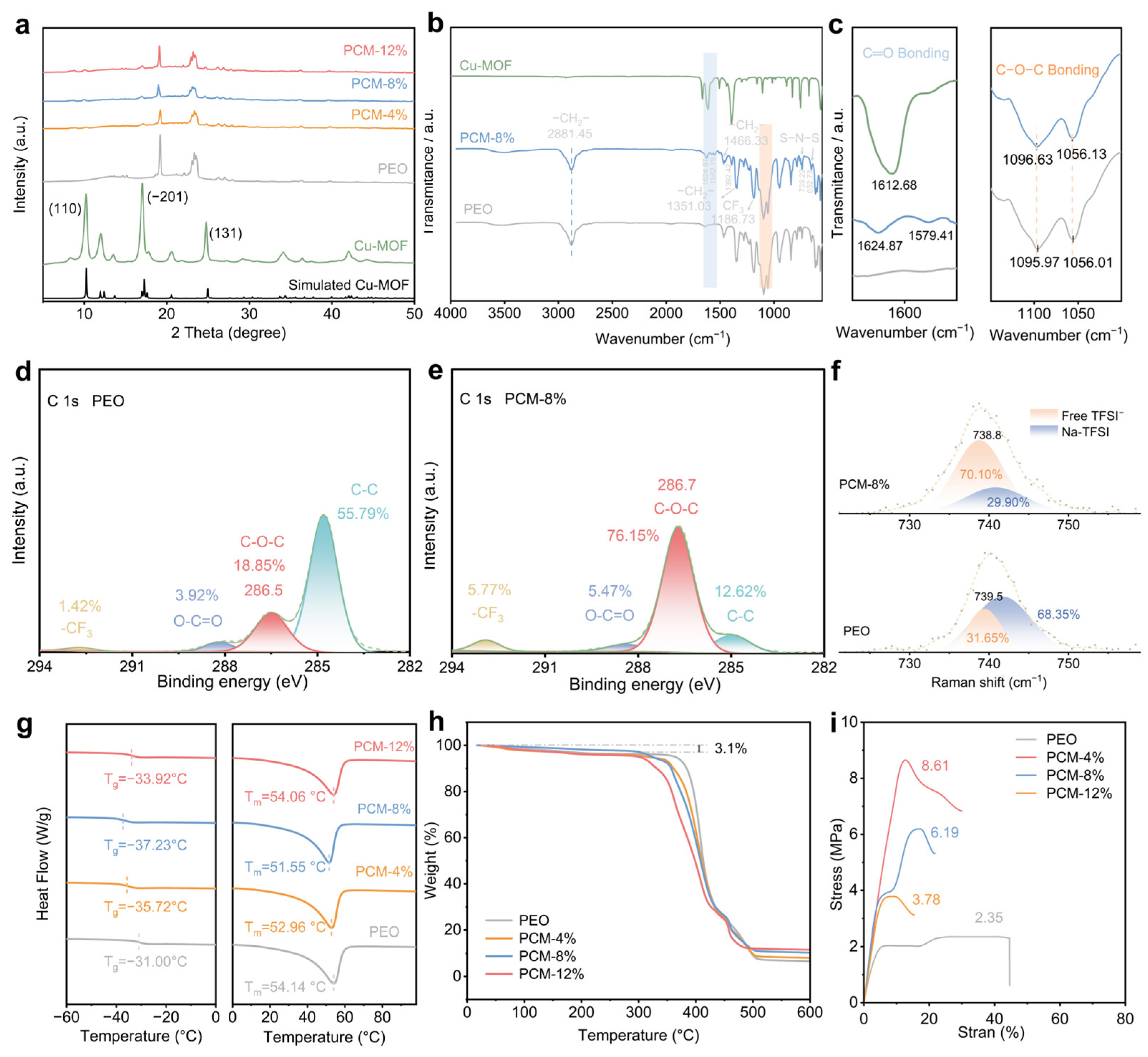
First, X-ray diffraction (XRD) was employed to characterize the Cu-MOF and the as-prepared solid-state electrolyte membranes, as shown in Figure 2a. The results demonstrate that the characteristic peaks of the Cu-MOF match well with the simulated pattern reported in the previous literature (CCDC number: 687690), thus confirming the successful synthesis of the Cu-MOF. We note that a low-angle diffraction peak appears at approximately 8.3°, which may be attributed to residual coordinated DMF solvent molecules retained during the synthesis of Cu-MOF [23]. Furthermore, the XRD data show characteristic diffraction peaks of PEO at 19.2° and 23.4°. After the incorporation of Cu-MOF, the peak intensities decrease and the peaks broaden, indicating that the incorporation of Cu-MOF may suppress PEO crystallization to a certain extent [24].
To further investigate the interactions between the components, Fourier transform infrared spectroscopy (FTIR) analysis was conducted, and the results are displayed in Figure 2b,c. Compared with the spectrum of pristine PEO, both Cu-MOF and PCM-8% exhibit pronounced and characteristic absorption peaks in the C=O asymmetric stretching region. Specifically, the C=O peak of Cu-MOF appears at 1612.68 cm−1, while that of PCM-8% is located around 1624.87 cm−1. Notably, the C=O stretching vibration of PCM-8% undergoes a significant blue shift of 12.19 cm−1 relative to that of Cu-MOF, moving from 1612.68 to 1624.87 cm−1. This is attributed to the coordination interaction between the ether oxygen bonds in PEO and the unsaturated Cu2+ sites, which pulls the electron cloud of the carboxylate groups on the MOF ligand, resulting in a significantly enhanced C=O double-bond character and a shortened bond length [18]. This coordination also shifts the electron cloud of the oxygen atoms in the ether bonds of PEO toward the Cu side, leading to contraction of the C–O bonds [17]. Consequently, compared with the pristine PEO material, the asymmetric stretching vibration peaks of the ether bonds in the PCM-8% material exhibit a slight blue shift, increasing from 1095.97 cm−1 and 1056.01 cm−1 to 1096.63 cm−1 and 1056.13 cm−1, respectively.
X-ray photoelectron spectroscopy (XPS) was further employed to probe the interaction between PEO and the Cu-MOF nanoparticles. This interaction induces a certain structural distortion in PEO, which can be reflected by changes in the peak areas of the XPS spectra [25]. The C 1 s XPS spectrum (Figure 2d,e) exhibits four characteristic peaks corresponding to C–C (284.8 eV), C–O–C (286.5 eV), O–C=O (288.2 eV), and –CF3 (292.6 eV). In the PCM-8% sample, the area percentage of the C–O–C peak (286.7 eV) increases from 18.85% in the pristine PEO sample to 76.15%. This increase is likely attributed to the suppression of PEO crystallization by Cu-MOF, which increases the proportion of amorphous regions, thereby exposing more C–O–C active sites to participate in sodium ion transport [26]. Furthermore, the coordination interaction between the unsaturated Cu2+ sites on Cu-MOF and the ether oxygen bonds in PEO reduces the electron cloud density of the oxygen atoms in the ether bonds, leading to a shift toward higher binding energy, which is consistent with the previous FTIR observations. Raman spectroscopy can more clearly and convincingly confirm that the strong adsorption effect of the open Cu metal sites in Cu-MOF toward TFSI promotes the dissociation of the sodium salt. As shown in Figure 2f, significant changes in the characteristic peaks of TFSI are clearly observed in the Raman band at approximately 740 cm−1. Compared with the pristine PEO material, the PCM-8% sample exhibits a higher proportion of free TFSI (70.10%), indicating that the incorporation of Cu-MOF promotes the dissociation of the sodium salt and provides more mobile sodium ions [27].
Differential scanning calorimetry (DSC) measurements further provide key evidence for the reduction in PEO crystallinity within the composite electrolyte membranes. As shown in Figure 2g and Table S1, the pristine PEO sample exhibits a glass transition temperature (Tg) of −31.00 °C. As the Cu-MOF doping content increases to 8 wt%, the Tg gradually decreases to −37.23 °C, and the melting point decreases from 54.14 °C (PEO) to 51.55 °C. However, when the doping content reaches 12 wt%, the Tg shows a slight increase compared with the PCM-8% sample. This may be because, at low doping contents, the introduction of Cu-MOF reduces the crystallinity of PEO, increases the proportion of amorphous regions, and disrupts the chain entanglement of PEO. As a result, the segmental motion of PEO in the amorphous regions is accelerated, leading to a decrease in Tg [28,29]. When the MOF doping content becomes excessively high, local agglomeration occurs, forming physical crosslinking points that create a steric hindrance effect, which to some extent impedes segmental motion [30]. Additionally, the coordination interaction between Cu2+ and PEO also imposes constraints on polymer chain movement [31]. Therefore, the lowest glass transition temperature is achieved at a Cu-MOF doping content of 8 wt%. Based on the measured melting enthalpy (ΔHm), the crystallinity of PCM-8% (27.8%) is lower than that of pristine PEO (29.4%). However, at a doping level of 12% (28.9%), the crystallinity increases, which may be because the agglomeration and non-uniform distribution of excess Cu-MOF filler diminish its ability to suppress PEO crystallization [32]. The lower glass transition temperature and reduced crystallinity indicate that the PCM-8% sample exhibits faster polymer chain mobility, which can more effectively disrupt the ordered segmental arrangement of PEO molecules, thereby providing a larger amorphous region for sodium ion transport.
In addition, PCM exhibits remarkable stability over a wide temperature range. Thermogravimetric analysis (TGA, Figure 2h) reveals that PCM possesses a high decomposition temperature (>300 °C). Specifically, above 320 °C, the terephthalic acid ligands in the Cu-MOF within the PCM solid-state electrolyte membrane begin to decompose, leading to framework collapse. The range of 340–430 °C corresponds to the extensive decomposition of PEO, while the mass loss in the range of 430–500 °C is likely attributable to the thermal decomposition of NaTFSI [33]. Therefore, these systematic measurements indicate that the incorporation of Cu-MOF alters the thermodynamic properties of PEO, enabling the operation of solid-state batteries over a wide temperature range. The mechanical properties of the solid-state electrolyte membrane are of great importance for the safety performance of the battery. The tensile strength of the four solid-state electrolytes was measured by mechanical tensile tests, as shown in Figure 2i. The pristine PEO exhibits a tensile strength of only 2.35 MPa, whereas with increasing Cu-MOF content, the tensile strengths of PCM-4%, PCM-8%, and PCM-12% increase to 3.78 MPa, 6.19 MPa, and 8.61 MPa, respectively. The higher tensile strength indicates that the electrolyte membrane can withstand greater stress generated by dendrite growth, thereby suppressing short-circuiting caused by dendrite penetration through the separator.

3.3. Theoretical Investigation of the Sodium-Ion Migration Mechanism

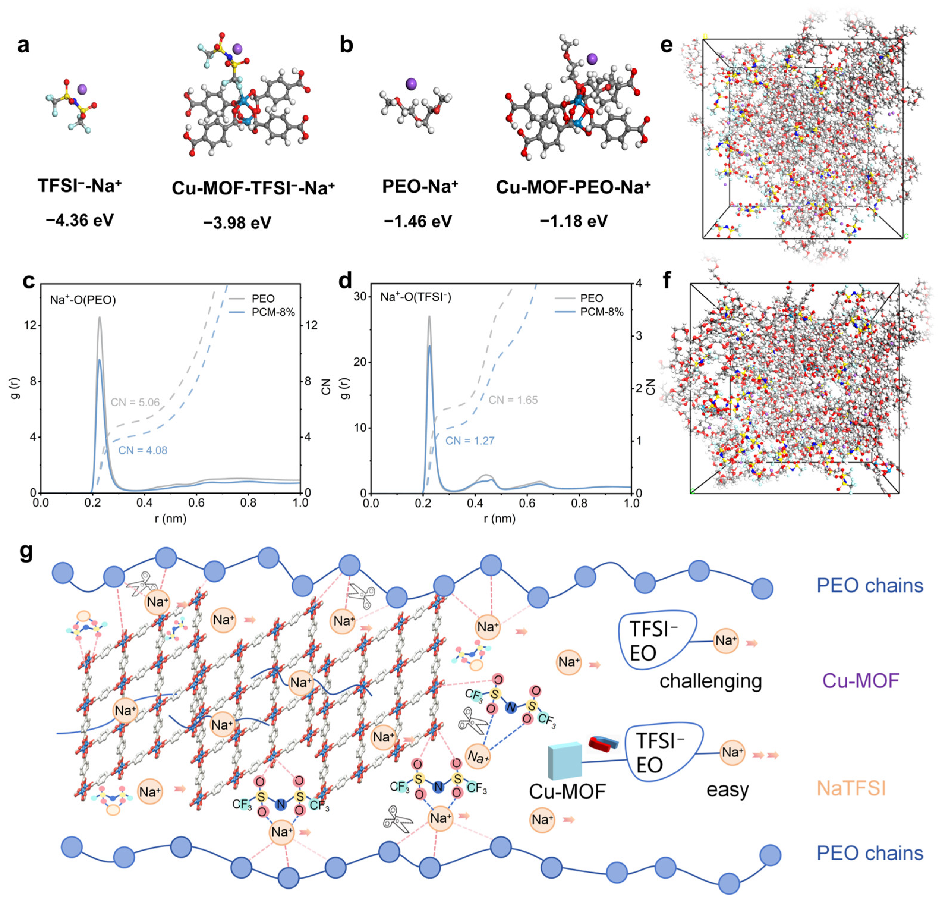
To elucidate the regulatory mechanism of Cu-MOF on the transport behavior of sodium ions, density functional theory (DFT) calculations were performed to determine the binding energies between various molecular species within the electrolyte, with the results presented in Figure 3a,b. The calculated results indicate that the introduction of Cu-MOF induces significant changes in the binding energies between TFSI and Na+, as well as between PEO segments (EO units) and Na+. Specifically, upon the introduction of Cu-MOF, the binding affinity between TFSI and Na+ in the system becomes relatively weaker. This finding suggests that Cu-MOF facilitates the dissociation of NaTFSI, releasing a greater number of free Na+ and thereby enhancing the migration kinetics of Na+. Moreover, the presence of Cu-MOF reduces the binding energy between PEO segments (EO units) and Na+, which benefits the transport of Na+. Collectively, these binding energy calculations provide molecular-level evidence supporting the regulatory role of Cu-MOF in ion transport.
Molecular dynamics (MD) simulations were further employed to investigate the interactions among Cu-MOF, TFSI, and PEO segments (EO units). As shown in Figure 3c,d, distinct differences in the microstructure and ionic coordination environment are observed between pristine PEO and PCM-8%. Na+ primarily coordinates with the oxygen sites of EO monomers in PEO, which is mainly attributed to the strong electron-donating ability of the ether oxygen bonds in EO monomers, facilitating the formation of stable coordination bonds with Na+. In the PEO material, the high coordination numbers (CN) of Na+ with the oxygen atoms of EO monomers and with the TFSI anion indicate that the migration of Na+ is strongly constrained, which often leads to severe concentration polarization in the battery. In PCM-8%, the decreased intensity of the coordination peaks and the reduced coordination numbers for Na+ with the oxygen atoms of TFSI and EO monomers suggest an accelerated diffusion rate of Na+. This further demonstrates that Cu-MOF weakens the coordination confinement of TFSI and EO monomers on Na+, which is fully consistent with the observed trends in binding energy changes.
In summary, the simulation results confirm at the molecular scale that the introduction of Cu-MOF effectively regulates the coordination environment of sodium ions in the matrix, thereby enhancing the sodium ion transport kinetics of the composite solid electrolyte. The underlying regulatory mechanism is illustrated in Figure 3g. On the one hand, Na+ can migrate through coordination and dissociation with the oxygen sites of EO monomers in PEO. Benefiting from the competitive coordination effect between Cu-MOF and EO monomers, the coordination confinement of EO monomers on Na+ is weakened, facilitating ion transport [18]. In addition, the presence of Cu-MOF can further enhance ionic conduction by suppressing PEO crystallization. On the other hand, Na+ can also migrate through the one-dimensional channels within the MOF, where abundant OMS exist. These OMS adsorb TFSI, thereby releasing more free Na+ and accelerating the transport of Na+ within the polymer electrolyte.

3.4. Electrochemical Characterization of Na|SPEs|Na Symmetric Cells

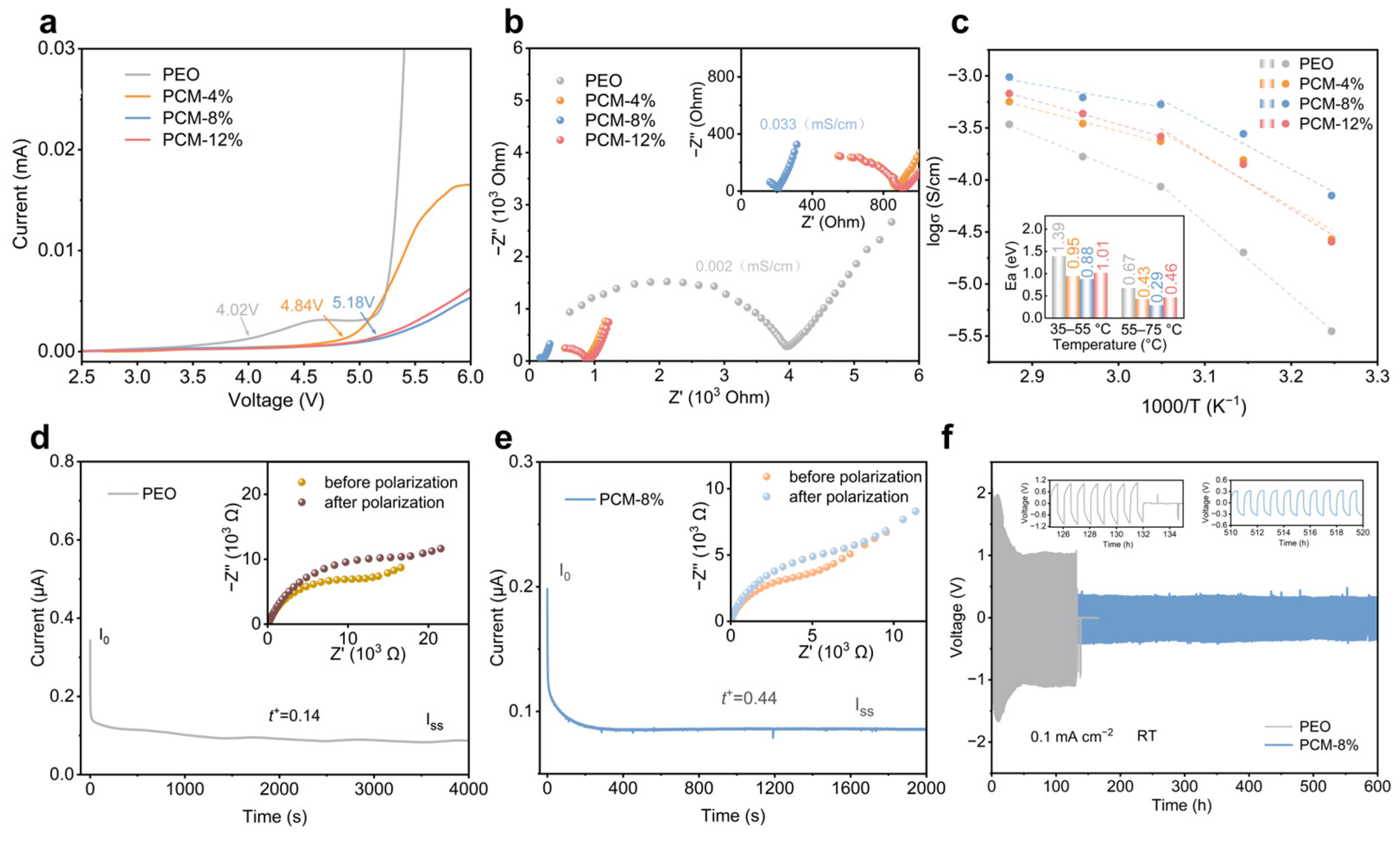
To evaluate the electrochemical performance of the prepared solid-state electrolyte membranes, linear sweep voltammetry (LSV) was first employed to measure the electrochemical windows of the PEO and PCM solid-state electrolytes. As shown in Figure 4a, the pristine PEO electrolyte undergoes oxidative decomposition at 4.02 V. With the incorporation of 4 wt% Cu-MOF, the stable electrochemical window is extended to 4.84 V. Notably, the PCM-8% membrane delivers the widest stable electrochemical window of 5.18 V. The enhanced oxidation potential may be attributed primarily to the coordination of Cu-MOF with the terminal hydroxyl groups of PEO, which reduces the reactivity of the coordinated hydroxyl groups and thereby retards their oxidative decomposition at high voltages [34,35]. In contrast, the PCM-12% membrane exhibits a slight decrease in the oxidation potential, likely due to the increased interfacial defects caused by MOF agglomeration [32,36]. The wide electrochemical window significantly improves the compatibility of the PCM electrolyte with cathode materials such as sodium vanadium phosphate (Na3V2(PO4)3) and enables stable operation at 4.0 V and beyond.
To quantify the influence of the physicochemical behaviors characterized above on sodium-ion transport capability, electrochemical impedance spectroscopy (EIS) was employed to measure the ionic conductivities of the PEO and PCM electrolytes. As shown in Figure 4b and Table S2, at room temperature, PCM-8% exhibits the highest ionic conductivity of 0.033 mS cm−1, which is approximately 16 times that of pristine PEO (0.002 mS cm−1). This result convincingly demonstrates that the enhanced segmental motion arising from the incorporation of Cu-MOF effectively promotes ion transport. In contrast, the room-temperature ionic conductivity of PCM-12% (0.012 mS cm−1) is lower than that of PCM-8%. This may be due to the aggregation of particles caused by an excess of Cu-MOF, which disrupts the continuous ion transport pathways and, to some extent, reduces the efficiency of sodium ion transport [33].
On this basis, the ionic conductivities of these electrolytes were measured at various temperatures (35–75 °C) (Figure S4). As the temperature increased, the ionic conductivities of all solid-state electrolytes increased accordingly, with PCM-8% consistently exhibiting the highest ionic conductivity. At 65 °C, the ionic conductivity of PCM-8% further increased to 0.62 mS cm−1, meeting the practical operational requirements over a wide temperature range. The temperature dependence of the ionic conductivity was further fitted using the Arrhenius equation, and the results are shown in Figure 4c. The calculated activation energies for ion transport indicate that PCM-8% possesses an activation energy of only 0.88 eV at low-to-medium temperatures (35–55 °C), which is significantly lower than that of PEO (1.39 eV). Moreover, PCM-8% exhibits the lowest activation energy (0.29 eV) at medium-to-high temperatures (55–75 °C). This behavior is attributed to the fact that at low-to-medium temperatures, PEO is predominantly crystalline, and ions migrate slowly along grain boundaries or within the limited amorphous regions, resulting in a high activation energy. When the temperature exceeds the melting point of PEO, the crystalline state transitions to an amorphous state, enhancing the mobility of polymer chains. Additionally, at elevated temperatures, the MOF becomes activated by the removal of solvent molecules, generating more unsaturated metal sites and facilitating unimpeded ion transport channels, thereby significantly reducing the activation energy [13]. These results again confirm, from a kinetic perspective, that the introduction of Cu-MOF more effectively lowers the kinetic barrier for PEO segment motion and enhances ion transport.
Subsequently, the sodium ion transference numbers of PEO and PCM-8% were measured at room temperature. As shown in Figure 4d,e, the sodium ion transference number of PCM-8% reaches 0.44, markedly higher than that of pristine PEO (0.14). It is well known that a high sodium ion transference number helps reduce the ion concentration gradient at the sodium electrode surface and effectively suppresses sodium dendrite growth. Cu-MOF promotes the release of more sodium ions by attracting TFSI; simultaneously, the one-dimensional microporous channels of Cu-MOF further reduce the migration resistance. These findings are mutually consistent with the conclusions drawn from our theoretical calculations and molecular simulations.
Since the PCM-8% electrolyte with an 8% doping level exhibits the highest ionic conductivity, Na|SPEs|Na symmetric cells were assembled using the PCM-8% electrolyte and tested at room temperature to evaluate the cycling stability during sodium plating/stripping, with the PEO solid-state electrolyte serving as a control. As shown in Figure 4f, the PCM-8% symmetric cell can stably cycle for 600 h at a current density of 0.1 mA cm−2, whereas the pristine PEO symmetric cell displays a short cycling life and is prone to micro-short circuits, failing after only 120 h, with an overpotential reaching 1.02 V. This can be attributed to the unbalanced migration of anions and the uncontrolled growth of sodium dendrites [26]. In contrast, through the incorporation of Cu-MOF, the PCM-8% material possesses excellent mechanical properties that effectively suppress dendrite growth and induce uniform sodium deposition. Furthermore, Cu-MOF increases the sodium-ion transference number by attracting TFSI, thereby mitigating concentration polarization and yielding a more stable voltage plateau during cycling. Consequently, the cycling stability is significantly improved.

3.5. Electrochemical Characterization of Na3V2(PO4)3/C(NVP/C)|SPEs|Na Cells

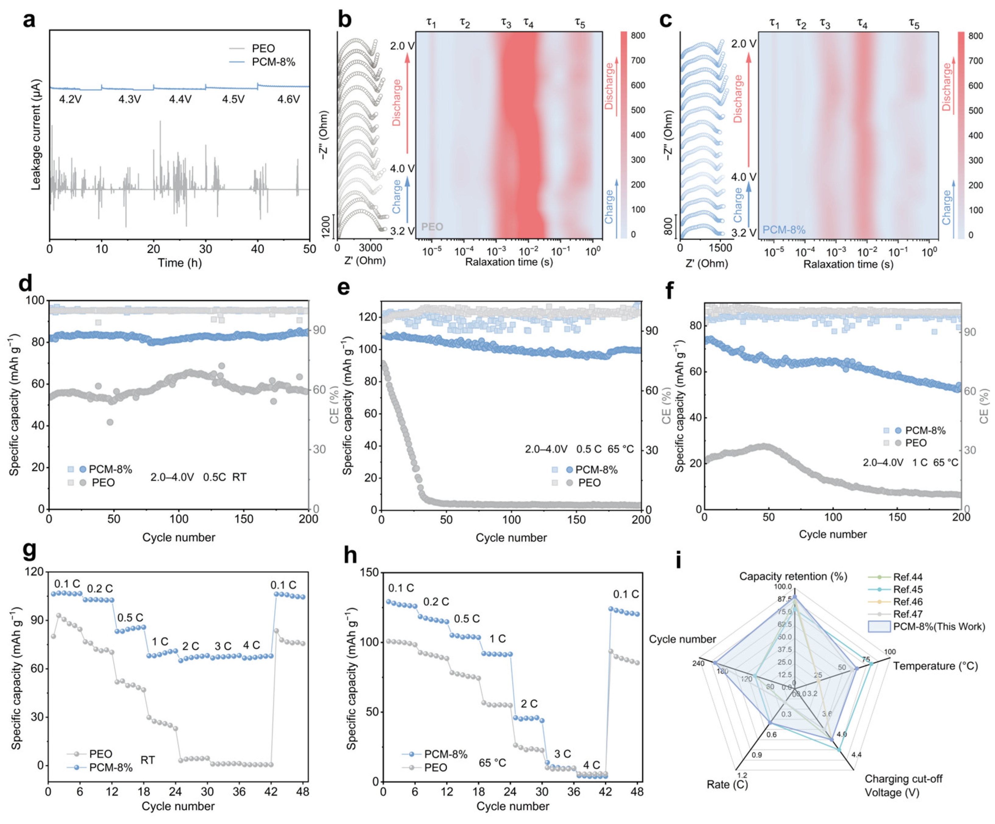
To further evaluate the electrochemical performance of the PCM-8% electrolyte under practical conditions, an NVP/C|PCM-8%|Na cell was assembled and tested, with the PEO solid-state electrolyte serving as a control. The electrochemical stability of the PEO and PCM-8% electrolytes at 4.2–4.6 V was first characterized by electrochemical floating potential tests (Figure 5a). The results reveal that the pristine PEO electrolyte displays numerous sharp current spikes, which stem from instantaneous micro-short-circuit caused by extensive sodium dendrite growth and membrane penetration during the charging process [37]. In contrast, PCM-8, with its superior mechanical properties, effectively suppresses dendrite growth and ensures safe operation of the full cell. Additionally, the leakage current of PCM-8% is significantly lower than that of PEO, demonstrating the excellent electrochemical stability of the PCM-8% electrolyte under high voltage [38].
To further investigate the evolution of interfacial impedance, in situ electrochemical impedance spectroscopy (EIS) measurements were conducted at various voltages (Figure 5b,c and Figure S5), and the kinetic characteristics at the interfaces were analyzed using the distribution of relaxation times (DRT) method. The Nyquist plots primarily consist of an ohmic resistance, a high-frequency semicircle, a mid-frequency semicircle, and a low-frequency feature, corresponding to the bulk resistance (Rohm), the interfacial resistance (Rint) for Na+ transport through the solid electrolyte interphase (SEI) and cathode electrolyte interphase (CEI), the charge transfer resistance (Rct), and the diffusion process, respectively [39]. Accordingly, the DRT analysis deconvolutes the complex impedance dynamics into five distinct relaxation processes (τ1: bulk ohmic resistance, τ2: heterogeneous interface polarization, τ3: electrode interface, τ4: charge transfer, and τ5: Na+ diffusion) [40,41]. In the PEO electrolyte, the high intensities of the τ3 and τ4 peaks indicate elevated interfacial and charge transfer resistances, suggesting the presence of an unstable interface in PEO that leads to sluggish charge transfer across the SEI/CEI and consequently increased cell polarization. In contrast, the corresponding impedances of the PCM-8% material are significantly reduced, which can be attributed to the increased population of free mobile Na+ within the material. This promotes dynamic interfacial stabilization, enhances ion transport, and induces the formation of an interfacial film with high ionic conductivity [34].
Leveraging the favorable adaptability of the as-prepared solid-state electrolyte membrane at both room and moderate-to-high temperatures, a series of galvanostatic charge–discharge tests were performed at room temperature and 65 °C. Cycling performance analysis (Figure 5d,f and Figure S6) reveals that at room temperature, PCM-8% retains a specific discharge capacity of 113.23 mAh g−1 after 80 cycles at 0.1 C, and delivers 85.23 mAh g−1 after 200 cycles at 0.5 C. Meanwhile, the corresponding voltage profiles (Figure S7) demonstrate stable cycling with negligible capacity fading. In contrast, pristine PEO exhibits a low initial capacity, which gradually increases to 65.48 mAh g−1 over the first 110 cycles with small fluctuations. This indicates that PEO suffers from poor initial interfacial contact, where high interfacial impedance and an unstable interface hinder Na+ migration. During subsequent cycling, activation and wetting with the cathode material partially improve interfacial transport, yet the interface remains unstable, and the specific capacity drops to 56.36 mAh g−1 after 200 cycles [42]. At the moderate-to-high temperature of 65 °C, the PCM-8% full cell delivers a capacity of 99.42 mAh g−1 after 200 cycles at 0.5 C, corresponding to a capacity retention of 91.4%. In sharp contrast, the pristine PEO full cell suffers from rapid capacity fade during cycling due to its inferior ionic conductivity and low sodium ion transference number. Additionally, it is worth noting that at the same C-rate, the full cell exhibits more pronounced capacity fading and fluctuating Coulombic efficiency at 65 °C than at room temperature. This may be attributed to the elevated temperature exacerbating the interfacial side reactions with the sodium metal anode and the oxidative decomposition of the sodium salt and PEO, which manifests as rapid capacity decay during cycling [43].
In addition, the NVP/C|PCM-8%|Na cell also demonstrates excellent rate capability. As shown in Figure 5g,h, at room temperature, PCM-8% delivers a specific discharge capacity of 71.02 mAh g−1 at 1 C, which is significantly higher than that of pristine PEO (29.85 mAh g−1). When the current density is increased to 4 C, it still maintains a specific capacity of 67.92 mAh g−1, indicating stable ion transport performance. Notably, at the moderate-to-high temperature of 65 °C, PCM-8% exhibits higher specific discharge capacities at lower rates, achieving a high capacity of 114.76 mAh g−1 at 0.2 C and still providing a reversible specific discharge capacity of 92.03 mAh g−1 at 1 C. However, a certain degree of capacity fading is observed as the current density increases to 4 C. This may arise because, at high rates, local overheating induced by the large current causes PEO recrystallization and slight softening of PEO, leading to interfacial failure that increases the resistance of the continuous ion transport pathways. This adverse effect outweighs the benefit of enhanced segmental motion at elevated temperatures, ultimately resulting in a lower capacity [43]. Figure 5i presents a comparison with state-of-the-art PEO solid-state electrolytes reported in recent years, from which it is evident that the PEO composite solid electrolyte incorporating Cu-MOF possesses more pronounced advantages and holds great practical application potential in the field of all-solid-state sodium metal batteries [44,45,46,47].
Figure 5. Investigation on electrochemical properties of NVP/C|Na Cell. (a) Electrochemical floating experiments of NVP/C| Na cells assembled with PEO and PCM-8% electrolytes. In situ EIS spectra during the process of the first charge/discharge and the corresponding DRT results of the NVP/C |Na cells at 0.1 C with (b) PEO and (c) PCM-8% electrolytes. Cycling performance of the NVP/C|Na cells with PEO and PCM-8% electrolytes (d) at 0.5 C at RT, (e) at 0.5 C at 65 °C and (f) at 1 C at 65 °C. Rate performance of the NVP/C|Na cells with PEO and PCM-8% electrolytes (g) at RT and (h) at 65 °C. (i) Comparisons of the cycling performance between some representative reported SSIBs and this work [44,45,46,47].
Nanoenergyadv 06 00023 g005

4. Conclusions

To address the issues of low ionic conductivity and poor mechanical properties in PEO-based solid polymer electrolytes, we successfully achieved synergistic modification of the PEO electrolyte by introducing Cu-MOF fillers to prepare a composite electrolyte. Experimental results confirmed that Cu-MOF, acting as a nanofiller, hinders the ordered arrangement of PEO segments and increases the proportion of amorphous regions. Additionally, by attracting TFSI, Cu-MOF promotes sodium salt dissociation and enhances the transport kinetics of sodium ions. In addition, the one-dimensional microporous channels in the Cu-MOF synergistically promote sodium ion migration. Theoretical calculations and molecular simulations have also demonstrated the regulatory role of Cu-MOF in ion transport. By leveraging these unique mechanisms to mitigate concentration polarization and suppress the uncontrolled growth of sodium dendrites, PCM-8% exhibits excellent electrochemical performance over a wide temperature range. Symmetric Na|PCM-8%|Na cells achieve a stable cycling life of 600 h, and NVP/C|PCM-8%|Na cells show almost no capacity decay after 200 cycles at 0.5 C at room temperature. At a rate of 4 C, the capacity remains at 67.92 mAh g−1, significantly outperforming that of unmodified PEO (0.56 mAh g−1 at 4 C). Notably, PCM-8% exhibits an even higher specific discharge capacity at 65 °C, delivering 99.42 mAh g−1 after 200 cycles at 0.5 C. This work expanded the research path for the development of high-performance solid-state sodium batteries with a wide temperature range.

Supplementary Materials

The following supporting information can be downloaded at: https://www.mdpi.com/article/10.3390/nanoenergyadv6030023/s1, Figure S1: The components of Cu-MOF and the corresponding crystal structure; Figure S2: TEM images of Cu-MOF. Figure S3: SEM images of PEO electrolyte membranes; Figure S4: Nyquist plots of (a) PEO, (b) PCM-4%, (c) PCM-8% and (d) PCM-12% at different temperatures (35–75 °C); Figure S5: In situ EIS spectra during the process of the first charge/discharge and the corresponding DRT results of the Na|NVP/C cells at 0.1 C with (a) PEO and (b) PCM-8%; Figure S6: Cycling performance of NVP/C/PCM-8%/Na cell at room temperature under a current density of 0.1 C; Figure S7: Charge–discharge curves of the NVP/C/PCM-8%/Na cell at room temperature under a current density of 0.5 C; Table S1: Values of Tm, ΔHm and χc of PEO, PCM-4%, PCM-8% and PCM-12% solid electrolytes from the DSC test. Table S2: Room-temperature ionic conductivities of various solid electrolytes.

Author Contributions

Methodology, Y.W.; Software, H.F. and B.L.; Validation, Y.W., H.F., B.L. and Q.Z.; Formal analysis, H.F.; Investigation, B.L. and Z.C.; Resources, H.F., Z.C. and H.L.; Data curation, Y.W., B.L., Q.Z., Z.C. and H.L.; Writing—original draft, Y.W.; Writing—review & editing, Y.W. and H.F.; Visualization, Z.C., H.L. and H.Z.; Supervision, H.Z.; Project administration, H.Z.; Funding acquisition, H.Z. All authors have read and agreed to the published version of the manuscript.

Funding

This work was supported by the Natural Science Foundation of Hunan Province [2020JJ4117].

Data Availability Statement

The original contributions presented in this study are included in the article and Supplementary Materials. Further inquiries can be directed to the corresponding author.

Acknowledgments

We are grateful for resources from the High Performance Computing Center of Central South University.

Conflicts of Interest

The authors declare no conflicts of interest.

References

  1. Zhao, S.; Che, H.; Chen, S.; Tao, H.; Liao, J.; Liao, X.-Z.; Ma, Z.-F. Research progress on the solid electrolyte of solid-state sodium-ion batteries. Electrochem. Energy Rev. 2024, 7, 3. [Google Scholar] [CrossRef]
  2. Liu, Q.; Zhao, X.; Yang, Q.; Hou, L.; Mu, D.; Tan, G.; Li, L.; Chen, R.; Wu, F. The progress in the electrolytes for solid state sodium-ion battery. Adv. Mater. Technol. 2023, 8, 2200822. [Google Scholar] [CrossRef]
  3. Munir, T.; Tariq, A.; Shaheen, S.; Asghar, R.; Noor, R. Shifting trends: Exploring different polymer hosts and polyelectrolyte systems for efficient sodium-ion batteries. J. Energy Storage 2024, 98, 113045. [Google Scholar] [CrossRef]
  4. Junoh, H.; Awang, N.; Zakria, H.S.; Zainuddin, N.A.S.; Nordin, N.A.H.M.; Suhaimin, N.S.; Enoki, T.; Uno, T.; Kubo, M. Advancements in polyethylene oxide (PEO)–active filler composite polymer electrolytes for lithium-ion batteries: A comprehensive review and prospects. Materials 2024, 17, 4344. [Google Scholar] [CrossRef] [PubMed]
  5. Li, J.; Li, J.; Wan, L.; Li, Z. Advances in poly(ethylene oxide)-based solid-state lithium-ion battery research. Soft Matter 2025, 21, 3410–3424. [Google Scholar] [CrossRef] [PubMed]
  6. Wang, J.-C.; Zhou, W.-J.; Zhang, N.; Wang, P.-F.; Yi, T.-F. Review on poly(ethylene oxide)-based solid electrolytes: Key issues, potential solutions, and outlook. Energy Fuels 2024, 38, 18395–18412. [Google Scholar] [CrossRef]
  7. Lu, Z.; Wan, E.; Zhou, K.; Miao, J.; Zhao, X.; Xiao, L. Fluorinated solvent additive and low-cost sodium salt synergistically improve the electrochemical interface stability of flame-retardant phosphate-based electrolytes in sodium metal batteries. Nanoenergy Adv. 2026, 6, 14. [Google Scholar] [CrossRef]
  8. Helaley, A.; Zhan, G.; Liang, X. Tailored PEO/PEG-PPG polymer electrolyte for solid-state lithium-ion battery. J. Electrochem. Soc. 2024, 171, 110509. [Google Scholar] [CrossRef]
  9. Paul, S.C.; Wunder, S.L.; Zdilla, M. Succinonitrile3 /NaPF6: A low-temperature molecular crystal and high-concentration electrolyte for high-voltage sodium ion batteries. Cryst. Growth Des. 2026, 26, 4133–4138. [Google Scholar] [CrossRef]
  10. Chen, G.; Bai, Y.; Gao, Y.; Wang, Z.; Zhang, K.; Ni, Q.; Wu, F.; Xu, H.; Wu, C. Inhibition of crystallization of poly(ethylene oxide) by ionic liquid: Insight into plasticizing mechanism and application for solid-state sodium ion batteries. ACS Appl. Mater. Interfaces 2019, 11, 43252–43260. [Google Scholar] [CrossRef] [PubMed]
  11. Ai, C.; Shu, Y.; Zhao, Z.; Guo, H.; Chen, S.; Yi, Q. Advances in the application of ionic liquids in PEO-based lithium-ion solid-state electrolytes: From the perspective of fillers. J. Mater. Chem. A 2025, 13, 13632–13656. [Google Scholar] [CrossRef]
  12. Liu, C.; Deng, L.; Li, X.; Wu, T.; Zhang, W.; Cui, H.; Yang, H. Metal–organic frameworks for solid-state electrolytes: A mini review. Electrochem. Commun. 2023, 150, 107491. [Google Scholar] [CrossRef]
  13. Kökçam-Demir, Ü.; Goldman, A.; Esrafili, L.; Gharib, M.; Morsali, A.; Weingart, O.; Janiak, C. Coordinatively unsaturated metal sites (open metal sites) in metal–organic frameworks: Design and applications. Chem. Soc. Rev. 2020, 49, 2751–2798. [Google Scholar] [CrossRef] [PubMed]
  14. Zhang, G.; Shu, J.; Xu, L.; Cai, X.; Zou, W.; Du, L.; Hu, S.; Mai, L. Pancake-like MOF solid-state electrolytes with fast ion migration for high-performance sodium battery. Nano-Micro Lett. 2021, 13, 105. [Google Scholar] [CrossRef] [PubMed]
  15. Zhang, H.; Zhou, Z.; Sun, X.; Zhang, Y.; Gao, Y. Metal organic framework MOF-74 based solid-state electrolytes for all-solid-state sodium metal batteries. J. Solid State Chem. 2024, 334, 124643. [Google Scholar] [CrossRef]
  16. Tang, X.; Liu, C.; Wang, H.; Lv, L.-P.; Sun, W.; Wang, Y. Pristine metal-organic frameworks for next-generation batteries. Coord. Chem. Rev. 2023, 494, 215361. [Google Scholar] [CrossRef]
  17. Wu, J.; Ma, Y.; Zhang, H.; Xie, H.; Hu, J.; Shi, C.; Chen, B.; He, C.; Zhao, N. Regulating metal centers of MOF-74 promotes PEO-based electrolytes for all-solid-state lithium-metal batteries. ACS Appl. Mater. Interfaces 2024, 16, 16351–16362. [Google Scholar] [CrossRef] [PubMed]
  18. Tian, W.; Lin, G.; Yuan, S.; Jin, T.; Wang, Q.; Jiao, L. Competitive coordination and dual interphase regulation of MOF-modified solid-state polymer electrolytes for high-performance sodium metal batteries. Angew. Chem. Int. Ed. 2025, 64, e202423075. [Google Scholar] [CrossRef] [PubMed]
  19. Han, J.; He, X.; Liu, J.; Ming, R.; Lin, M.; Li, H.; Zhou, X.; Deng, H. Determining factors in the growth of MOF single crystals unveiled by in situ interface imaging. Chem 2022, 8, 1637–1657. [Google Scholar] [CrossRef]
  20. Yu, J.; Guo, T.; Wang, C.; Shen, Z.; Dong, X.; Li, S.; Zhang, H.; Lu, Z. Engineering two-dimensional metal–organic framework on molecular basis for fast li+ conduction. Nano Lett. 2021, 21, 5805–5812. [Google Scholar] [CrossRef] [PubMed]
  21. Liu, Z.; Chu, J.; Cheng, L.; Wang, J.; Zhang, C.; Zhang, C.; Cui, F.; Wang, H.-G.; Zhu, G. A 3D four-fold interpenetrated conductive metal–organic framework for fast and robust sodium-ion storage. Chem. Sci. 2025, 16, 2810–2818. [Google Scholar] [CrossRef] [PubMed]
  22. Wang, M.; Braun, H.-G.; Meyer, E. Crystalline structures in ultrathin poly(ethylene oxide)/poly(methyl methacrylate) blend films. Polymer 2003, 44, 5015–5021. [Google Scholar] [CrossRef]
  23. Carson, C.G.; Hardcastle, K.; Schwartz, J.; Liu, X.; Hoffmann, C.; Gerhardt, R.A.; Tannenbaum, R. Synthesis and structure characterization of copper terephthalate metal–organic frameworks. Eur. J. Inorg. Chem. 2009, 2009, 2338–2343. [Google Scholar] [CrossRef]
  24. Guo, Z.; Guan, C.; Li, F.; Liao, S.; Hao, X.; Mu, J.; Huang, Z.; Wang, S.; Cai, D. Phthalocyanine nickel enhanced composite solid-state electrolytes with homogenous and fast li-ion conduction for high-voltage li-metal batteries. J. Colloid Interface Sci. 2025, 683, 1100–1113. [Google Scholar] [CrossRef] [PubMed]
  25. Wu, K.; Li, A.; Tan, J.; Zhou, F.; Yan, H.; Wang, P.; Xie, T.; Zeng, Q.; Han, C.; Liu, Q.; et al. SnF2 -catalyzed lithiophilic–lithiophobic gradient interface for high-rate PEO-based all-solid-state batteries. Angew. Chem. Int. Ed. 2024, 63, e202410347. [Google Scholar] [CrossRef] [PubMed]
  26. Zhou, F.; Fu, L.; Wu, Q.; Ding, C.; Yu, L.; Zhou, W.; Cao, F.; Liu, H.; Xu, J. Single-ion conductor covalently grafted onto MOFs to realize solid polymer electrolyte tripartite conducting channels in lithium metal batteries. Chem. Eng. J. 2025, 525, 170705. [Google Scholar] [CrossRef]
  27. Zha, H.; Wu, X.; Li, G.; Hu, J.; Chen, K.; Lei, M.; Liu, Y.; Zhou, Z.; Li, J.; Li, C. Polymer electrolytes reinforced by green cyclodextrin framework filler for all-solid-state conversion-type lithium metal batteries. Solid State Ion. 2025, 428, 116936. [Google Scholar] [CrossRef]
  28. Schneider, G.J. Dynamics of nanocomposites. Curr. Opin. Chem. Eng. 2017, 16, 65–77. [Google Scholar] [CrossRef]
  29. Chai, S.-C.; Xu, T.-Y.; Cao, X.; Wang, G.; Chen, Q.; Li, H.-L. Ultrasmall nanoparticles diluted chain entanglement in polymer nanocomposites. Chin. J. Polym. Sci. 2019, 37, 797–805. [Google Scholar] [CrossRef]
  30. Niu, Q.; Han, H.; Liu, X.; Li, B.; Li, H.; Li, Z. A rapid self-healing glassy polymer/metal–organic-framework hybrid membrane at room temperature. Dalton Trans. 2023, 52, 3148–3157. [Google Scholar] [CrossRef] [PubMed]
  31. Farzi, N.; Ebrahim, M. Mechanical properties and glass transition temperature of metal-organic framework-filled epoxy resin: A molecular dynamics study. Mater. Chem. Phys. 2024, 314, 128874. [Google Scholar] [CrossRef]
  32. Wu, Y.; Zhu, H.; Fu, Z.; Zhou, Q.; Zhang, P.; Qiang, S.; Zhang, H.; Jiang, H.; Guo, P.; Wang, Y.; et al. Hierarchically porous copper-based metal–organic framework for high-performance PEO-based solid-state electrolytes. J. Energy Storage 2026, 165, 122343. [Google Scholar] [CrossRef]
  33. Wang, Z.; Zheng, L.; Xu, Z.; Shi, J.; Dai, Z.; Li, X. Metal-organic framework (MIL-101Fe)-incorporated composite polymer electrolytes for all solid-state lithium-ion batteries. J. Power Sources 2025, 652, 237650. [Google Scholar] [CrossRef]
  34. Feng, L.; Shen, Z.; Yang, Q.; Zhang, J.; Chen, S. MOF-ionic liquid structured polymer electrolytes with multi-channel ion transport pathways for wide-temperature solid-state lithium batteries. Adv. Mater. 2025, 37, e12360. [Google Scholar] [CrossRef] [PubMed]
  35. An, H.; Li, M.; Liu, Q.; Song, Y.; Liu, J.; Yu, Z.; Liu, X.; Deng, B.; Wang, J. Strong lewis-acid coordinated PEO electrolyte achieves 4.8 V-class all-solid-state batteries over 580 wh kg−1. Nat. Commun. 2024, 15, 9150. [Google Scholar] [CrossRef] [PubMed]
  36. Yu, S.; Li, C.; Zhao, S.; Chai, M.; Hou, J.; Lin, R. Recent advances in the interfacial engineering of MOF-based mixed matrix membranes for gas separation. Nanoscale 2024, 16, 7716–7733. [Google Scholar] [CrossRef] [PubMed]
  37. Counihan, M.J.; Chavan, K.S.; Barai, P.; Powers, D.J.; Zhang, Y.; Srinivasan, V.; Tepavcevic, S. The phantom menace of dynamic soft-shorts in solid-state battery research. Joule 2024, 8, 64–90. [Google Scholar] [CrossRef]
  38. Huang, R.; Xiang, L.; Bian, F.; Cheng, J.; Jiang, Z.; Zhao, J.; He, M. Design of cross-linked polymer deep eutectic electrolytes for high-voltage long-cycle lithium metal batteries via solvation regulation of polymerizable deep eutectic solvent monomers. Adv. Energy Mater. 2026, 16, e05218. [Google Scholar] [CrossRef]
  39. Bai, X.; Zheng, C.; Zhang, H.; Liu, J.; Wang, P.; Xia, B.; Li, J. How do high-voltage cathode and PEO electrolyte get along well? EIS analysis mechanism & potentiometric control strategy. J. Energy Chem. 2024, 96, 424–436. [Google Scholar] [CrossRef]
  40. Lu, J.; Ma, Z.; Wang, Y.; Dai, W.; Cheng, X.; Zuo, J.; Lei, H.; Fu, Z. Toward high-energy-density initial-anode-free lithium-metal batteries via ultra-thin protective ion-transport-promoting interface modification and surface prelithiation. Small 2024, 20, 2406359. [Google Scholar] [CrossRef] [PubMed]
  41. Yuan, S.; Cao, S.; Chen, X.; Wei, J.; Lv, Z.; Xia, H.; Chen, L.; Ng, R.B.F.; Tan, F.L.; Li, H.; et al. Anion-modulated solvation sheath and electric double layer enabling lithium-ion storage from −60 to 80 °C. J. Am. Chem. Soc. 2025, 147, 4089–4099. [Google Scholar] [CrossRef] [PubMed]
  42. Sun, C.-C.; Yusuf, A.; Li, S.-W.; Qi, X.-L.; Ma, Y.; Wang, D.-Y. Metal organic frameworks enabled rational design of multifunctional PEO-based solid polymer electrolytes. Chem. Eng. J. 2021, 414, 128702. [Google Scholar] [CrossRef]
  43. Hu, L.; Gao, X.; Wang, H.; Song, Y.; Zhu, Y.; Tao, Z.; Yuan, B.; Hu, R. Progress of polymer electrolytes worked in solid-state lithium batteries for wide-temperature application. Small 2024, 20, 2312251. [Google Scholar] [CrossRef] [PubMed]
  44. Zhang, H.; Zhou, Z.; Sun, X.; Zhang, Y.; Xu, H.; Gao, Y. Copper-doped metal–organic framework-74 solid-state electrolytes for high performance all-solid-state sodium metal batteries. J. Colloid Interface Sci. 2025, 689, 137241. [Google Scholar] [CrossRef] [PubMed]
  45. Liu, J.; You, T.; Zhao, Y.; Liu, F.; Li, J.; Wang, L.; Wang, C.; Li, L. Multifunctional sulfonate additive induced CEI layer enables ultra-stable PEO based solid-state sodium batteries. Rare Met. 2025, 44, 3817–3826. [Google Scholar] [CrossRef]
  46. Jiang, Y.; Wang, R.; Xiong, P.; Liu, Y.; Li, H.; Zhang, L.; You, Y.; Zhang, C. A solid dual-salt plastic crystal electrolyte enabling rapid ion transfer and stable interphases for high-performance solid-state sodium ion batteries. Chem. Sci. 2026, 17, 4529–4537. [Google Scholar] [CrossRef] [PubMed]
  47. Qin, W.; Pan, W.; Zhang, J.; Tang, J.; Huang, J.; Tang, M.; Wang, Z. Modulating the overall properties of PEO/NaTFSI electrolytes via UiO-66 fibrous membranes with different functional groups for solid-state sodium metal batteries. ACS Appl. Energy Mater. 2026, 9, 4276–4284. [Google Scholar] [CrossRef]
Figure 1. (a) SEM images and EDS images of Cu-MOF. (b) N2 adsorption–desorption isotherms (BET plots) of Cu-MOF. Optical photographs of (c) PEO and (d) PCM-8% electrolyte membranes. (e) Thickness measurements of the PCM-8% electrolyte membrane at different positions. (f) SEM images and EDS images of PCM-8% electrolyte membranes.
Nanoenergyadv 06 00023 g001
Figure 2. (a) XRD patterns, (b) FTIR spectra of Cu-MOF, PEO, and PCM-8%; the blue regions represent C=O bonds, while the orange regions denote C−O−C bonds. (c) The right panel displays magnified views of these two bond types in sequence. XPS spectra of C 1 s for (d) PEO and (e) PCM-8% membranes. (f) Raman spectra of PEO and PCM-8% membranes. Physical and electrochemical properties of SPEs: (g) DSC curves, (h) TGA curves and (i) stress–strain curves of PEO, PCM-4%, PCM-8 %, and PCM-12% electrolytes.
Nanoenergyadv 06 00023 g002
Figure 3. Calculation of binding energies of (a) TFSI- Na+ and Cu-MOF-TFSI-Na+, (b) PEO-Na+ and Cu-MOF-PEO-Na+. g(r) and CN of (c) Na+-O (PEO) and (d) Na-O(TFSI). Snapshots of (e) PEO electrolyte and (f) PCM-8% electrolyte. (g) Na+ transport mechanisms in PCM-8% electrolyte.
Nanoenergyadv 06 00023 g003
Figure 4. Electrochemical Measurement of Na|Na Cell. (a) Electrochemical window, (b) Ionic conductivity, (c) activation energy of PEO, PCM-4%, PCM-8% and PCM-12%. Na+ transference number of (d) PEO electrolyte and (e) PCM-8% electrolyte. (f) The galvanostatic curves at 0.1 mA cm−2.
Nanoenergyadv 06 00023 g004
Disclaimer/Publisher’s Note: The statements, opinions and data contained in all publications are solely those of the individual author(s) and contributor(s) and not of MDPI and/or the editor(s). MDPI and/or the editor(s) disclaim responsibility for any injury to people or property resulting from any ideas, methods, instructions or products referred to in the content.