Second-Order Collocation-Based Mixed FEM for Flexoelectric Solids
Abstract
1. Introduction
2. Flexoelectricity: Constitutive and Governing Equations
3. Collocation Mixed Finite Element Method (CMFEM)
3.1. CMFEM for Linear Element
| Algorithm 1 Collocation method. | ||
| 1: | compute all | ▹ The inverse Jacobian matrix for all integration points (ip) |
| 2: | ||
| 3: | compute according to Equation (27) | ▹ and contain the B-Matrices derived |
| 4: | compute according to Equation (28) | ▹ from nodal values N for all collocation points |
| 5: | ||
| 6: | define | ▹ containing precalculated values of according to Equation (37) |
| 7: | ||
| 8: | for 1,…, do | ▹ Loop over all ip |
| 9: | ||
| 10: | compute according to Equation (32) | ▹ The P-vector for current ip |
| 11: | = (1,,,) | |
| 12: | ||
| 13: | compute and Equation (44) | ▹ The directional derivatives |
| 14: | ▹ of the P-vector for current ip | |
| 15: | = (0,,,+) | |
| 16: | = (0,,,+) | ▹ Use inverse Jacobian of current ip |
| 17: | ||
| 18: | compute according to Equation (41) | ▹ The collocated -matrix |
| 19: | ||
| 20: | compute according to Equation (42) | ▹ The directional derivative of -matrix |
| 21: | ||
| 22: | compute according to Equation (41) | ▹ The collocated -matrix |
| 23: | ||
| 24: | compute according to Equation (43) | ▹ The directional derivative of -matrix |
| 25: | ||
| 26: | … | |
| 27: | end for | |
3.2. CMFEM for Quadratic Element
4. Numerical Examples
4.1. Cantilever Beam Problem
4.1.1. Verification of Linear Element
4.1.2. Comparison of Linear and Quadratic Elements
4.1.3. Convergence Study
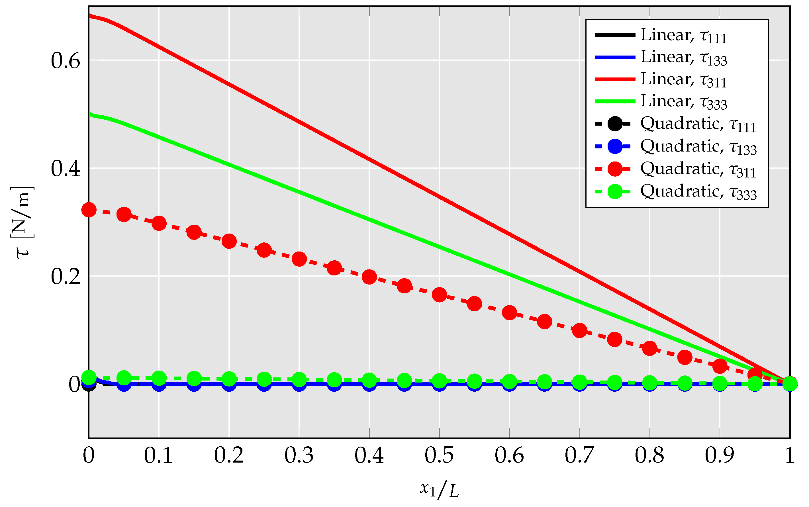
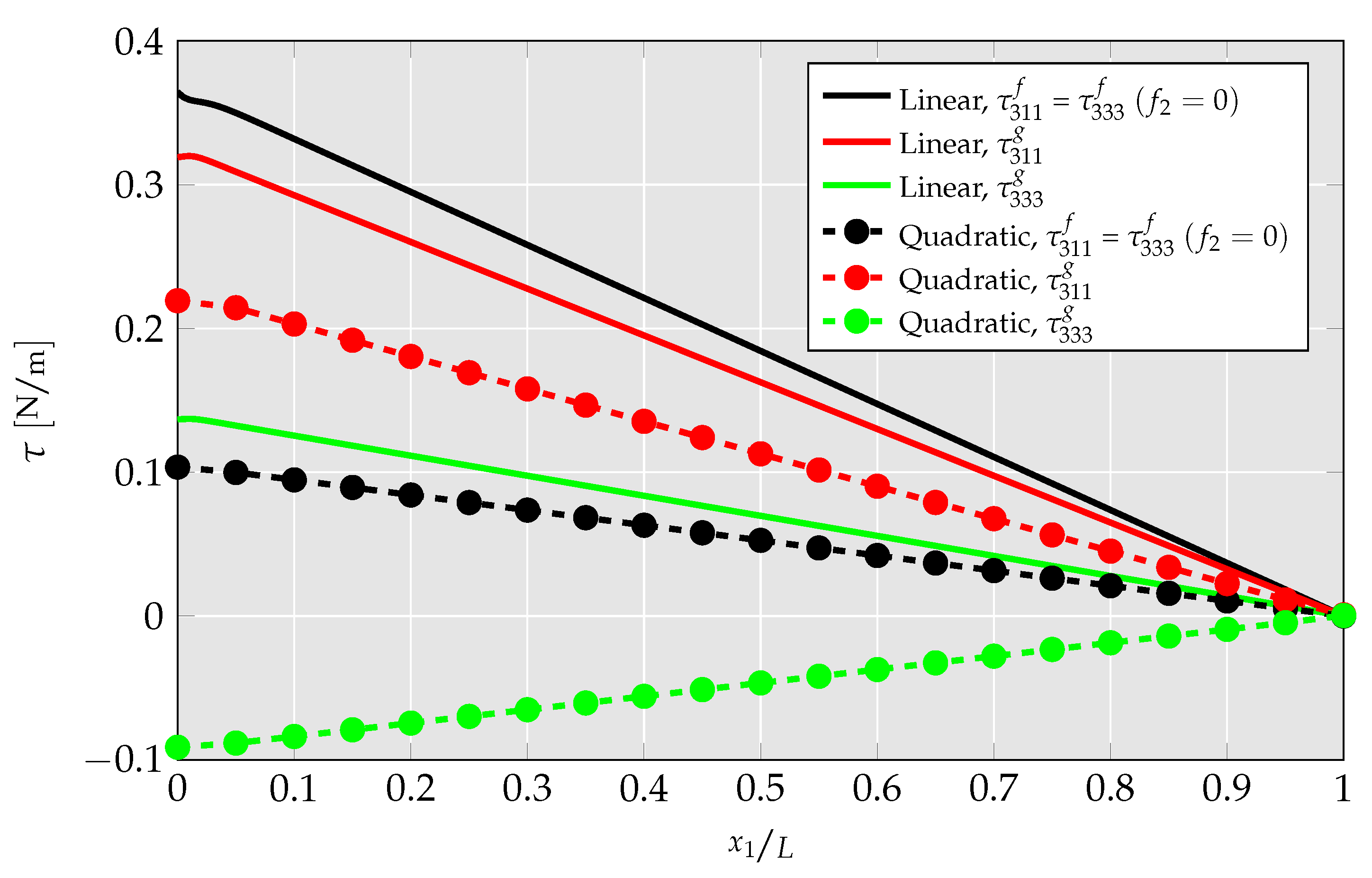
4.1.4. Investigation of Differences between Linear and Quadratic Elements
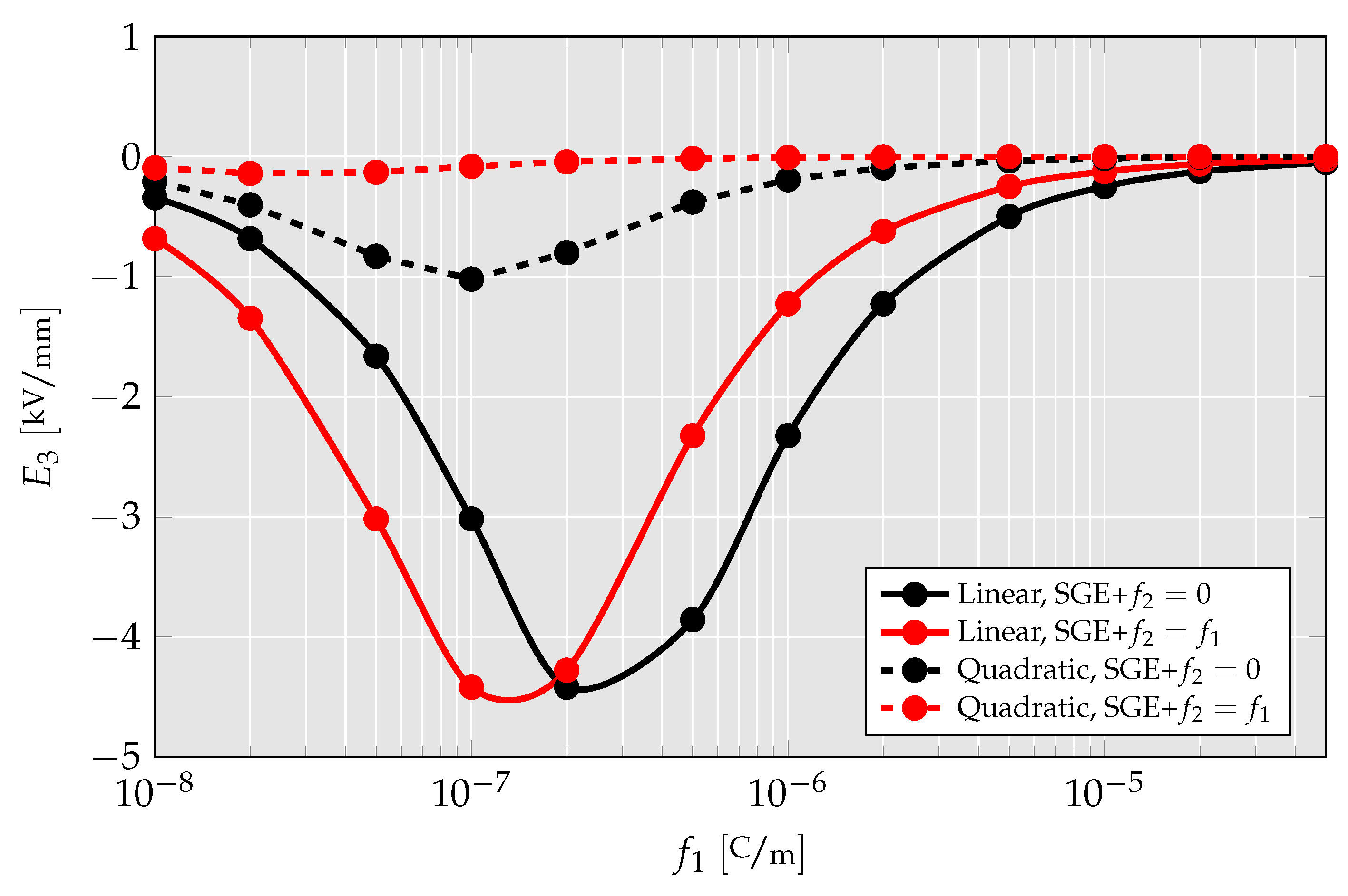
4.1.5. Parameter Study of Flexoelectric Coefficients
4.1.6. Discussion about the Advantages of Quadratic Element
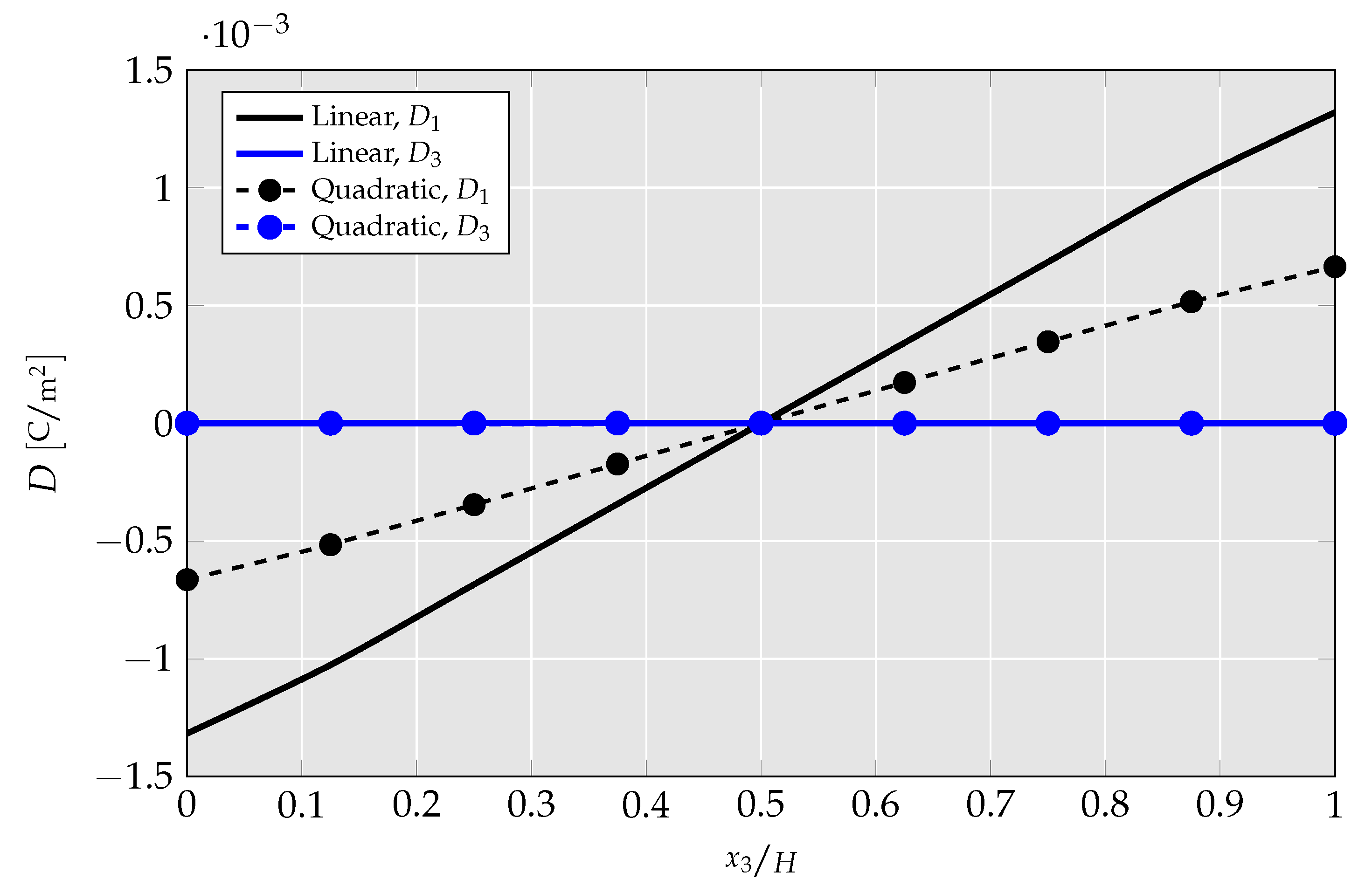
4.2. Truncated Pyramid Compression Problem
5. Conclusions
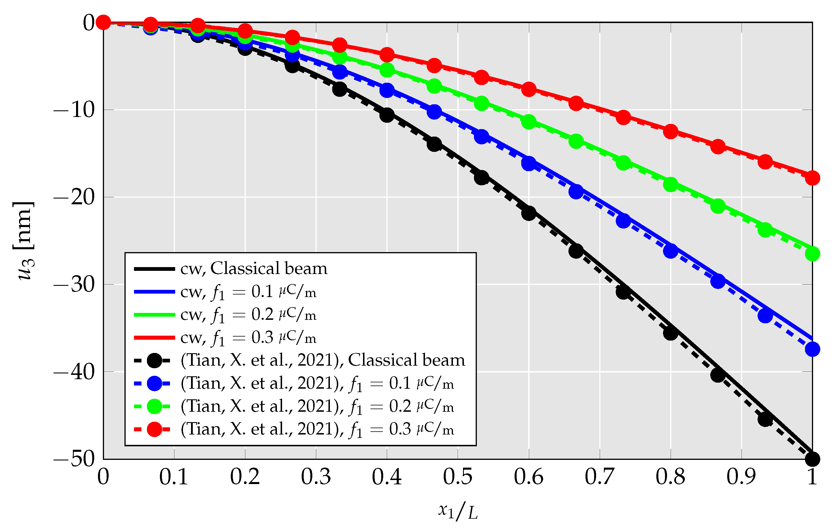
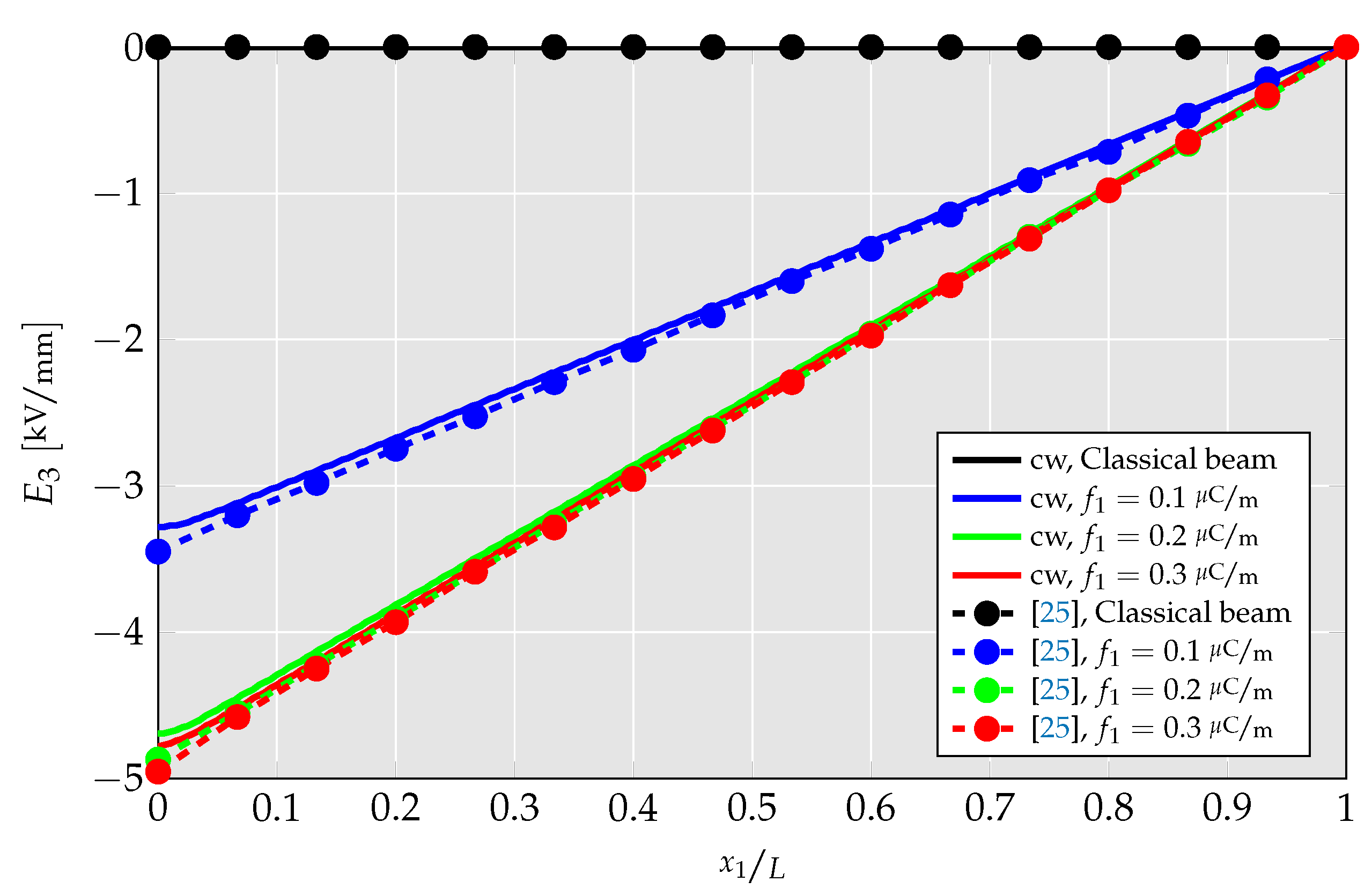
- A linear CMFEM element is developed and verified with numerical results for a 2D cantilever beam problem from the literature.
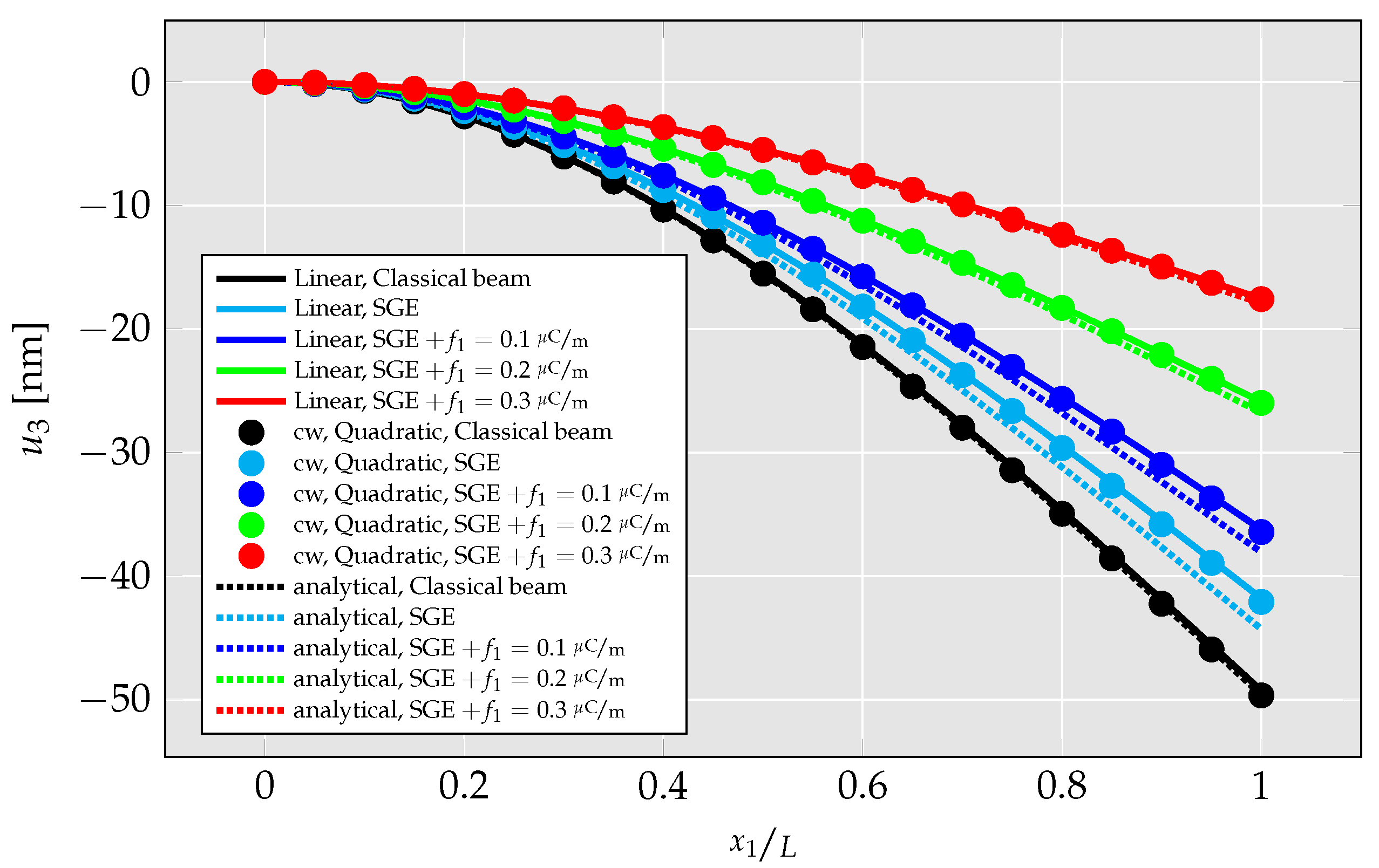
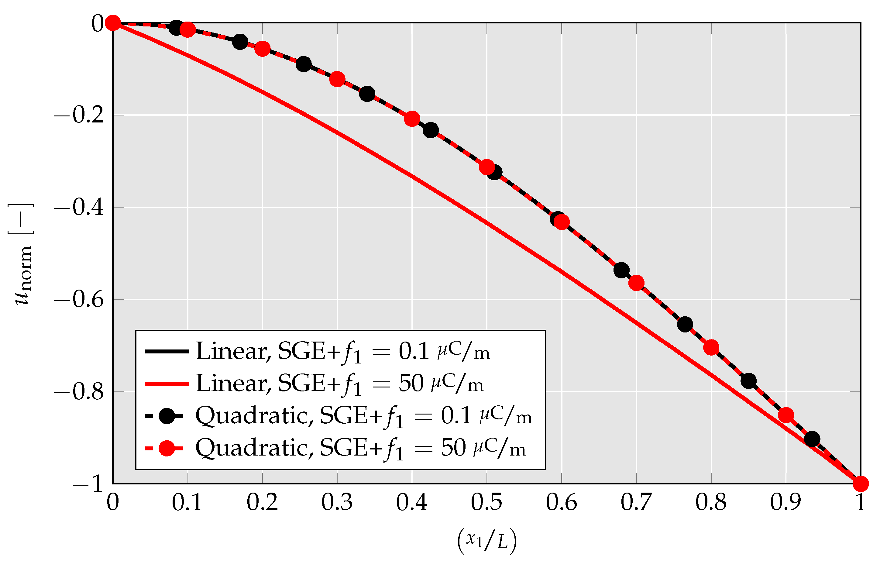
- The correctness of the newly proposed quadratic element is verified through comparison with the linear element and examples from the literature. To make the closest comparison, the strain gradient components, which cannot be computed by the linear element, are hardcoded to zero in the quadratic UEL.
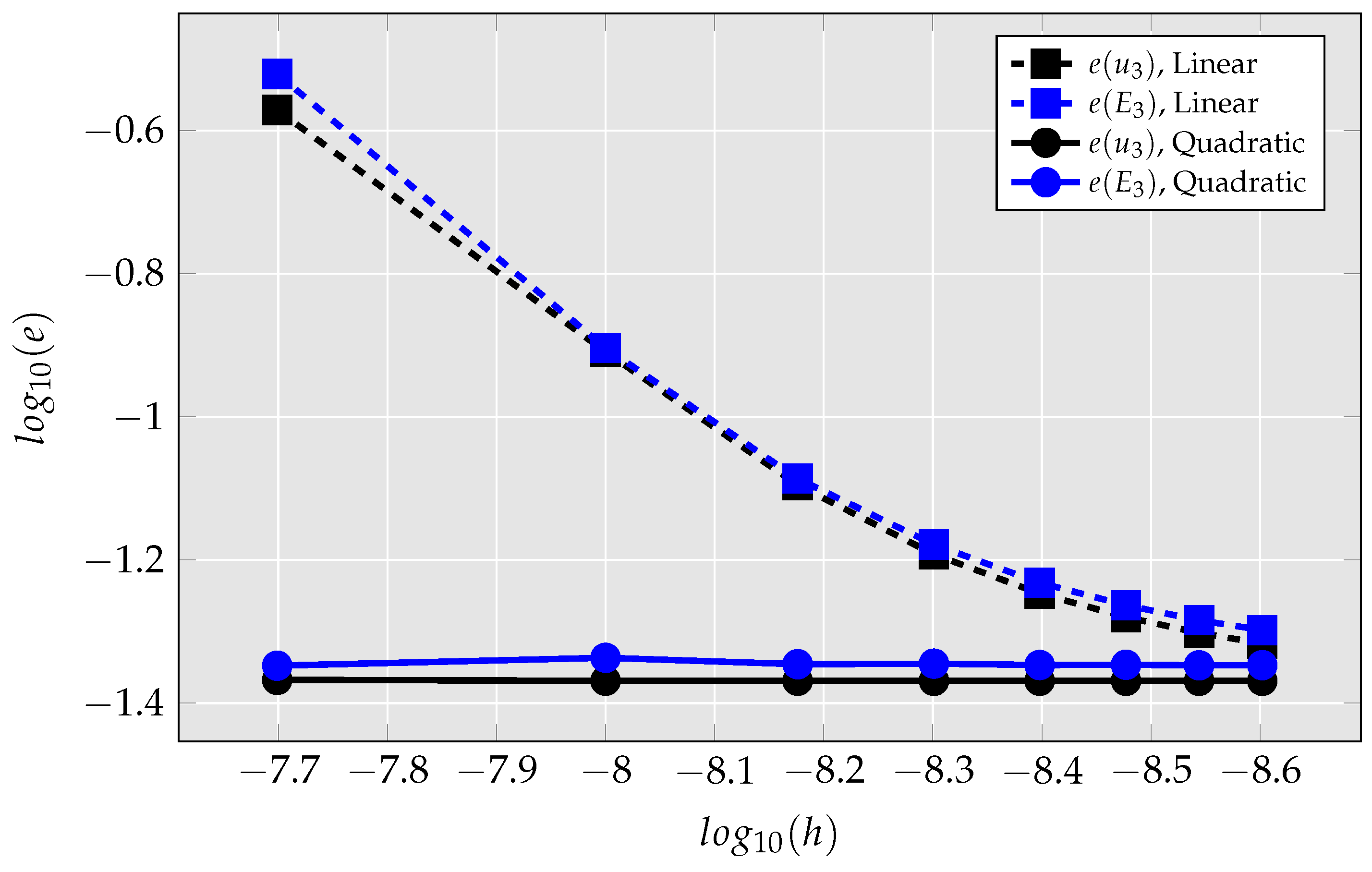
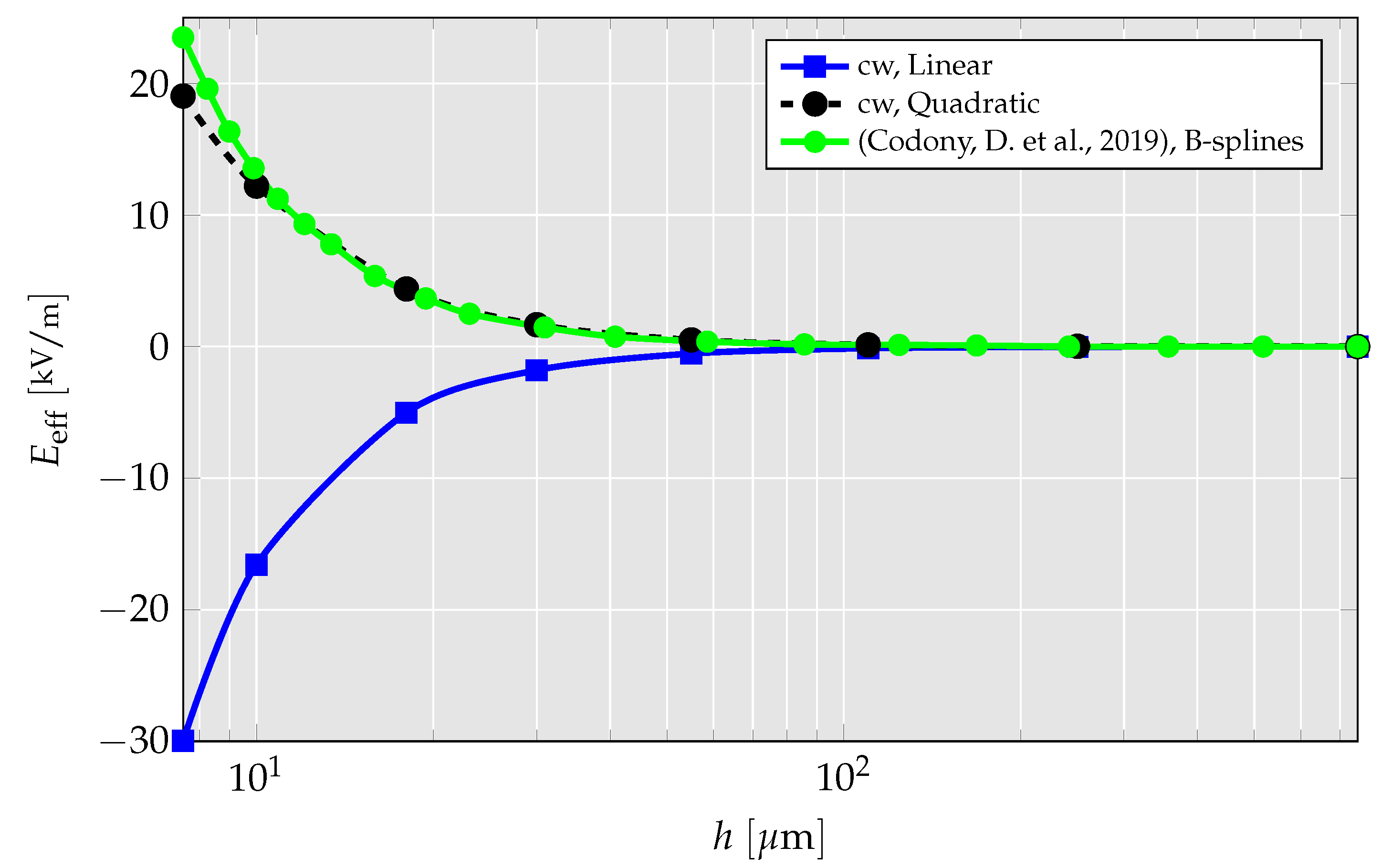
- Based on a convergence study, it is shown that the quadratic element is more accurate than the linear element. In particular, for meshes with very few elements, the accuracy is drastically improved with the usage of the newly developed quadratic element.
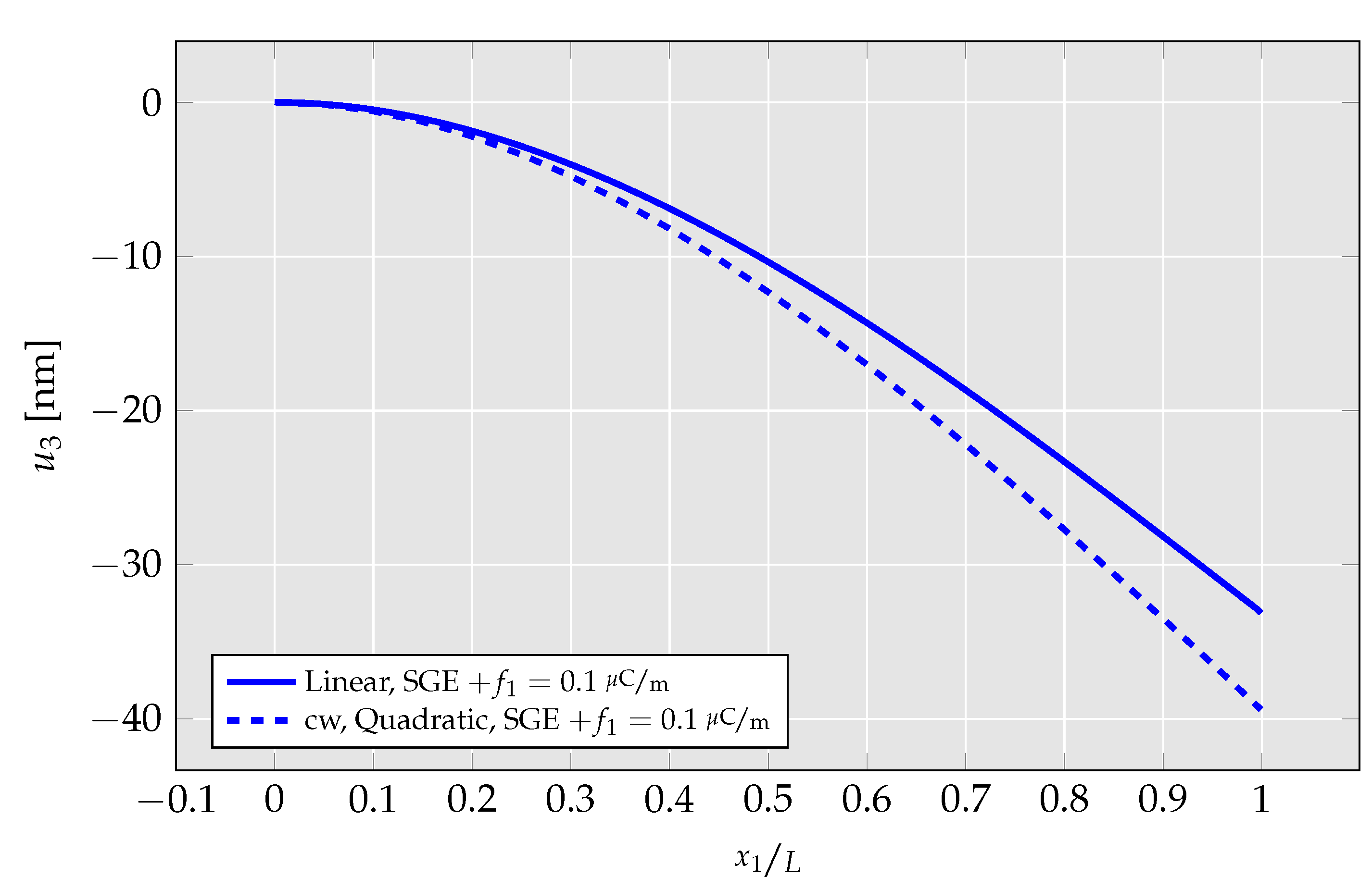
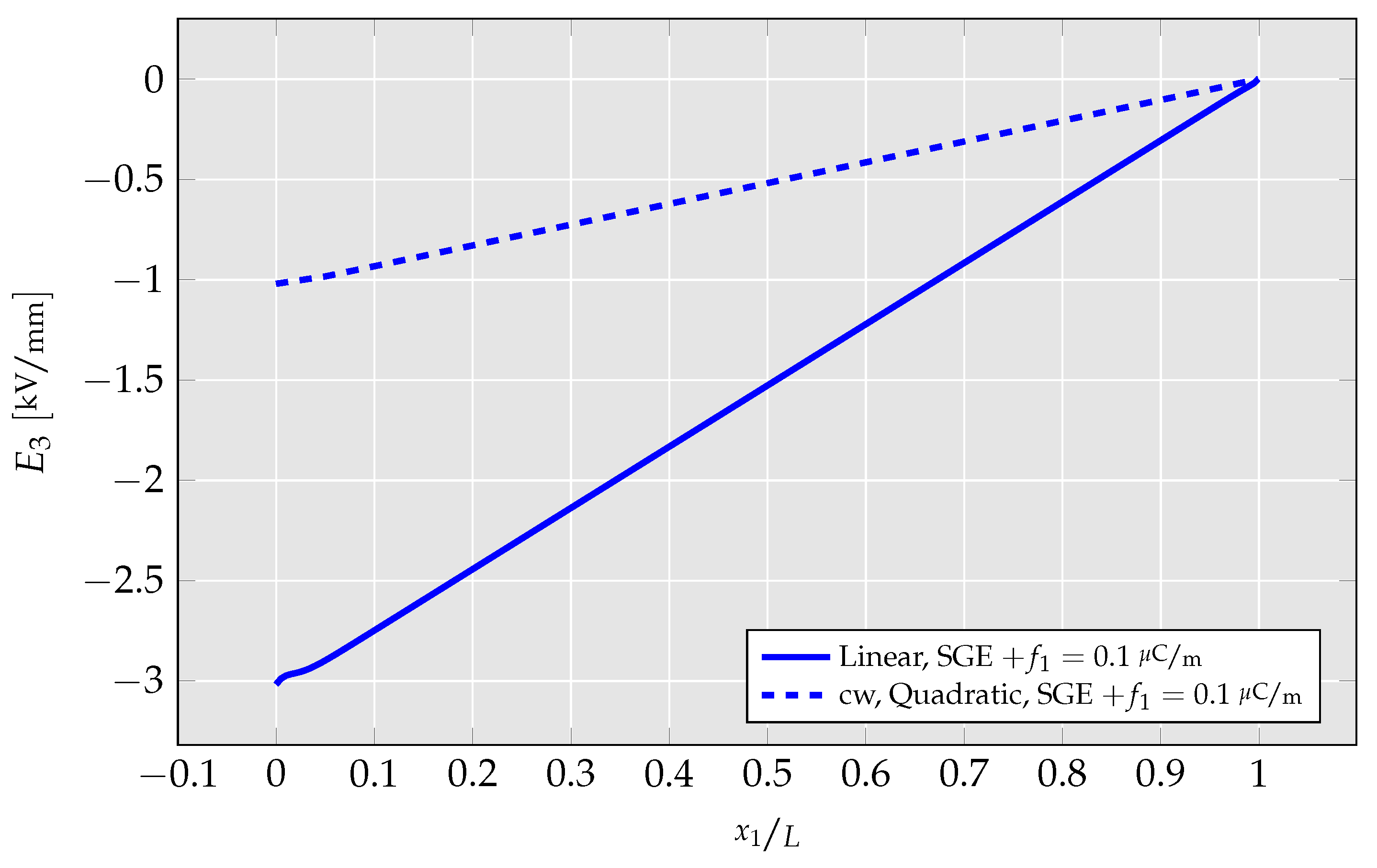
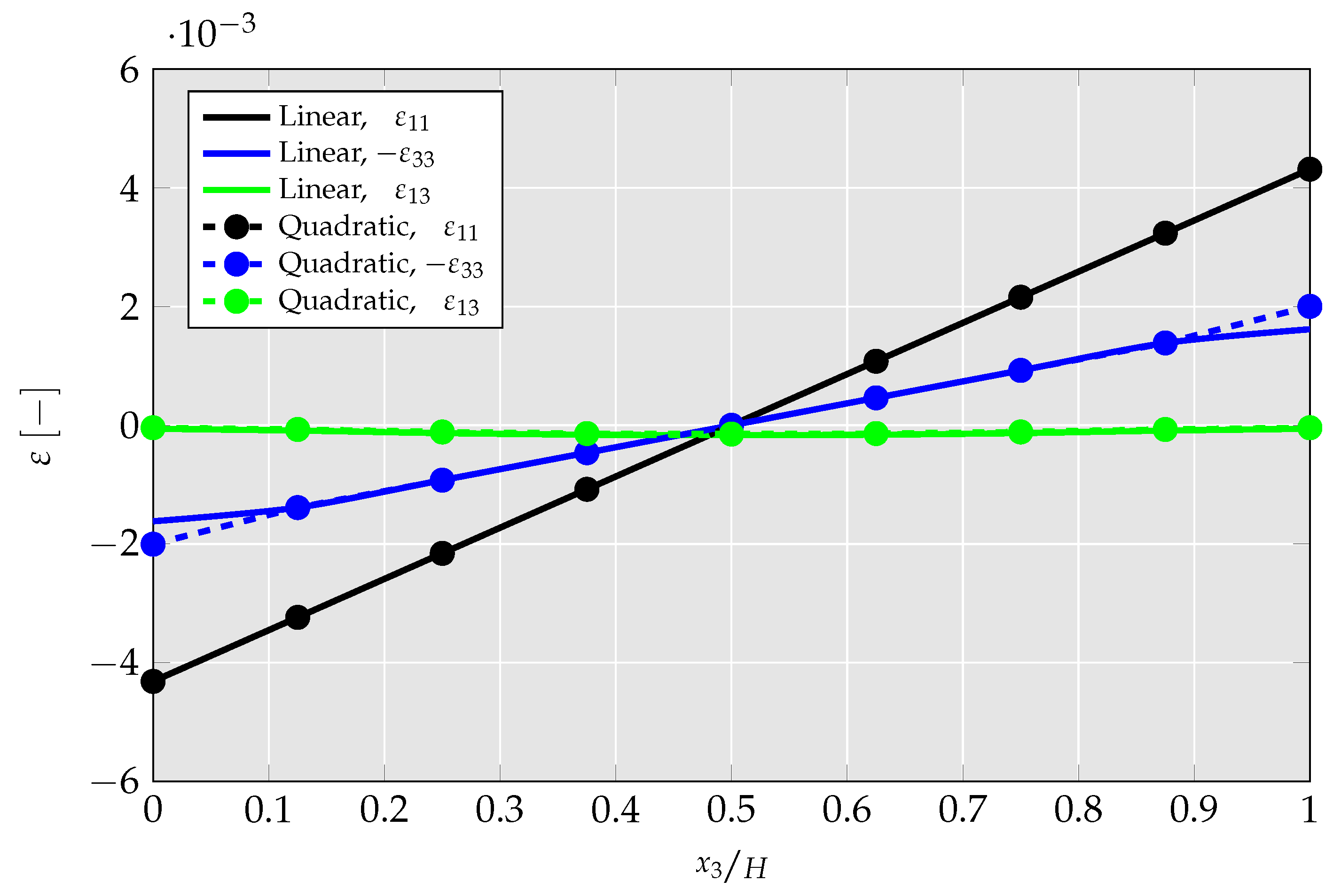
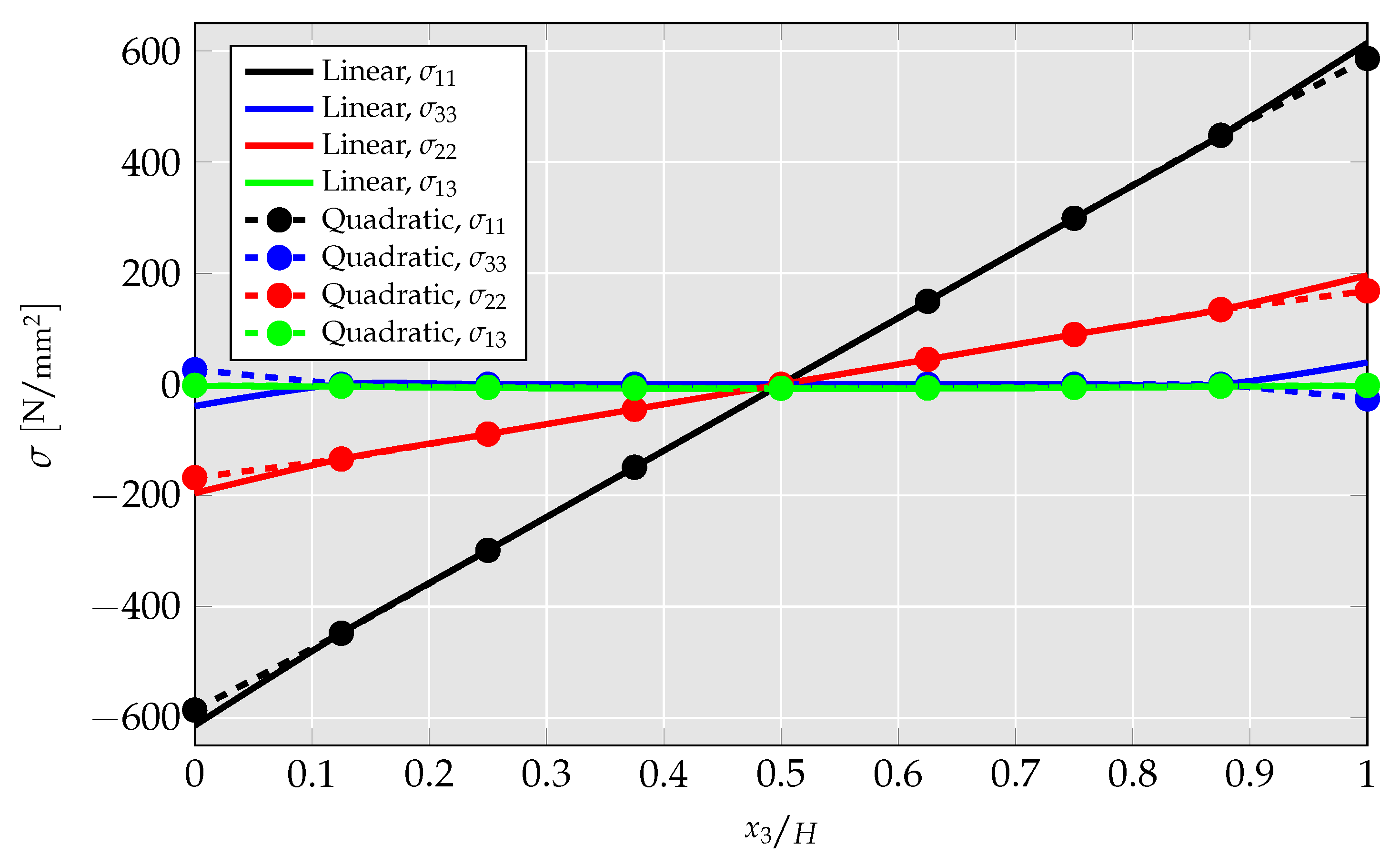
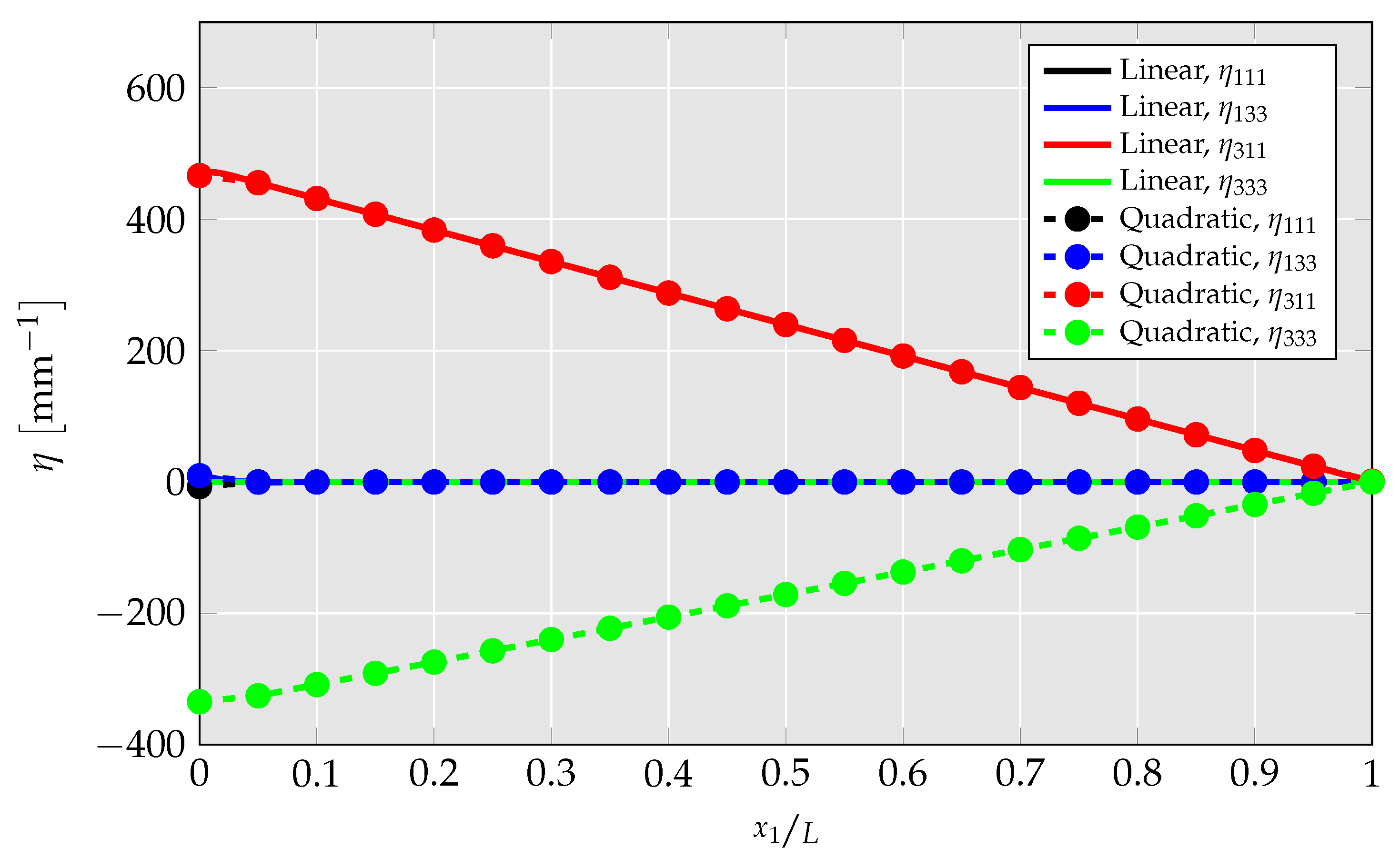
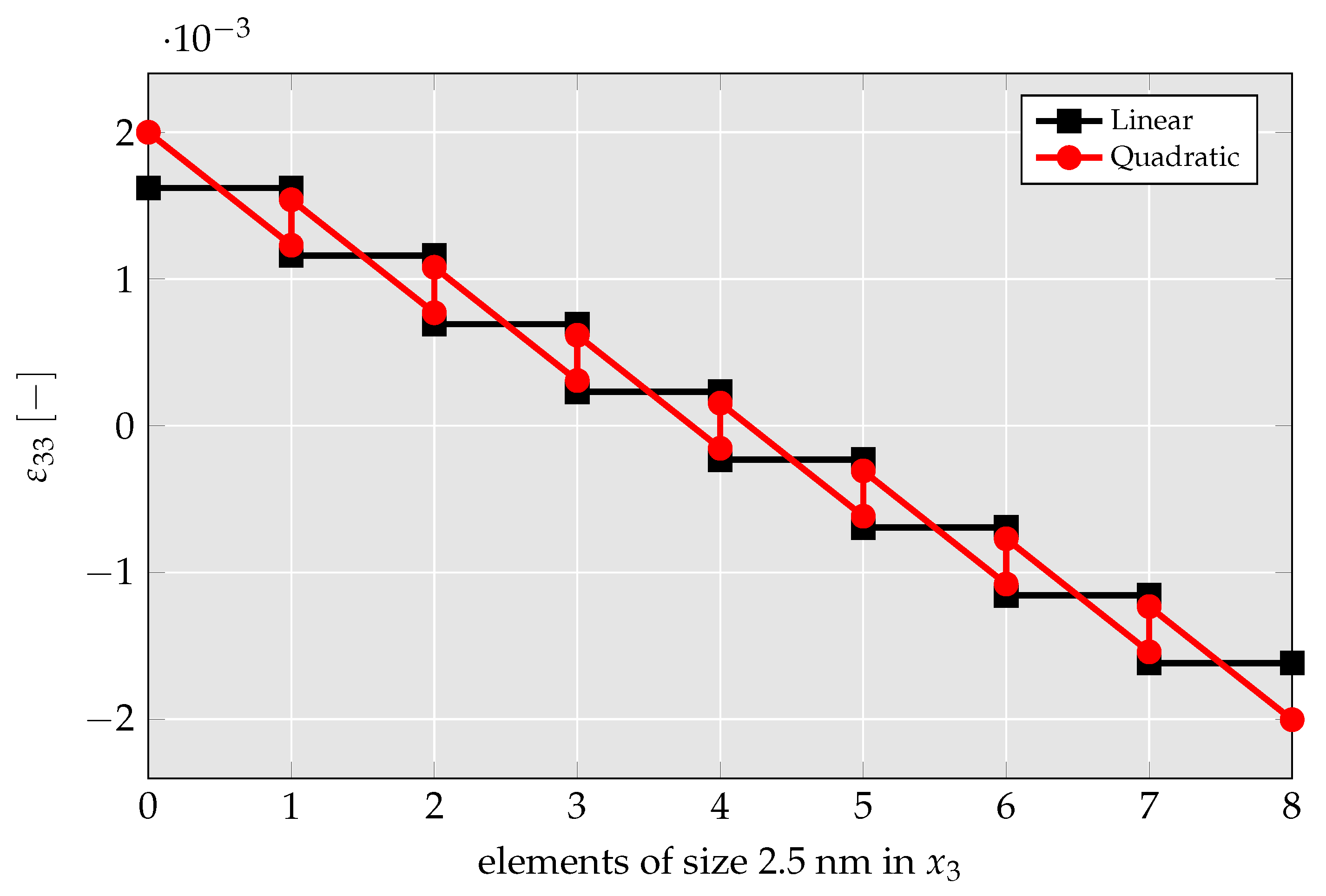
- By no longer hardcoding specific strain gradient components to zero in the quadratic UEL, CMFEM elements’ performance is analyzed. There, it is presented that mechanical strain gradient cannot be captured by the linear element, but has a relevant magnitude, leading to a strong overestimation of flexoelectric coupling and mechanical stiffness.
- The abovementioned findings are further investigated by a parameter study in which cantilever beam’s deflection and generated electric field are studied for a wide range of flexoelectric coefficients. There, it is found that using the linear element, the cantilever beams’ deflection nears zero for high flexoelectric coefficients and the remaining deflection is build-up only from shear stress. For the quadratic element, on the other hand, the deflection saturates at a nonzero value mimicking a physically realistic behavior.
- In the flexoelectric truncated pyramid example, although the linear element produced physically invalid results, the results of the quadratic element are in a very good agreement with the literature. The newly proposed quadratic element yields realistic results compared to those obtained in experiments [8,34] and a distribution of the electric field similar to [12,16]. This is additionally outlined in a simulation series wherein the flexoelectric size effect is visualized.
Author Contributions
Funding
Data Availability Statement
Conflicts of Interest
Abbreviations
| BVP | boundary value problem |
| CMFEM | collocation-based mixed finite element method |
| cw | current work |
| FEM | finite element method |
| MEMS | microelectromechanical systems |
| SGE | strain gradient elasticity |
| UEL | user element |
References
- Mashkevich, V.; Tolpygo, K. Electrical, optical and elastic properties of diamond type crystals. Sov. Phys. JETP 1957, 5, 435–439. [Google Scholar]
- Kogan, S.M. Piezoelectric effect during inhomogeneous deformation and acoustic scattering of carriers in crystals. Sov. Phys. Solid State 1964, 5, 2069–2070. [Google Scholar]
- Zubko, P.; Catalan, G.; Tagantsev, A.K. Flexoelectric effect in solids. Annu. Rev. Mater. Res. 2013, 43, 387–421. [Google Scholar] [CrossRef]
- Kozinov, S.; Kuna, M. Simulation of fatigue damage in ferroelectric polycrystals under mechanical/electrical loading. J. Mech. Phys. Solids 2018, 116, 150–170. [Google Scholar] [CrossRef]
- Catalan, G.; Sinnamon, L.; Gregg, J. The effect of flexoelectricity on the dielectric properties of inhomogeneously strained ferroelectric thin films. J. Phys. Condens. Matter 2004, 16, 2253. [Google Scholar] [CrossRef]
- Ma, W.; Cross, L.E. Large flexoelectric polarization in ceramic lead magnesium niobate. Appl. Phys. Lett. 2001, 79, 4420–4422. [Google Scholar] [CrossRef]
- Ma, W.; Cross, L.E. Flexoelectric polarization of barium strontium titanate in the paraelectric state. Appl. Phys. Lett. 2002, 81, 3440–3442. [Google Scholar] [CrossRef]
- Cross, L.E. Flexoelectric effects: Charge separation in insulating solids subjected to elastic strain gradients. J. Mater. Sci. 2006, 41, 53–63. [Google Scholar] [CrossRef]
- Catalan, G.; Lubk, A.; Vlooswijk, A.; Snoeck, E.; Magen, C.; Janssens, A.; Rispens, G.; Rijnders, G.; Blank, D.H.; Noheda, B. Flexoelectric rotation of polarization in ferroelectric thin films. Nat. Mater. 2011, 10, 963–967. [Google Scholar] [CrossRef]
- Hu, S.; Shen, S. Electric field gradient theory with surface effect for nano-dielectrics. Comput. Mater. Contin. 2009, 13, 63. [Google Scholar] [CrossRef]
- Xu, L.; Shen, S. Size-dependent piezoelectricity and elasticity due to the electric field-strain gradient coupling and strain gradient elasticity. Int. J. Appl. Mech. 2013, 5, 1350015. [Google Scholar] [CrossRef]
- Abdollahi, A.; Peco, C.; Millan, D.; Arroyo, M.; Arias, I. Computational evaluation of the flexoelectric effect in dielectric solids. J. Appl. Phys. 2014, 116, 093502. [Google Scholar] [CrossRef]
- Thai, T.Q.; Rabczuk, T.; Zhuang, X. A large deformation isogeometric approach for flexoelectricity and soft materials. Comput. Methods Appl. Mech. Eng. 2018, 341, 718–739. [Google Scholar] [CrossRef]
- Liu, C.; Wang, J.; Xu, G.; Kamlah, M.; Zhang, T.Y. An isogeometric approach to flexoelectric effect in ferroelectric materials. Int. J. Solids Struct. 2019, 162, 198–210. [Google Scholar] [CrossRef]
- Sladek, J.; Stanak, P.; Han, Z.; Sladek, V.; Atluri, S. Applications of the MLPG method in engineering & sciences: A review. CMES Comput. Model. Eng. Sci. 2013, 92, 423–475. [Google Scholar] [CrossRef]
- Codony, D.; Marco, O.; Fernández-Méndez, S.; Arias, I. An immersed boundary hierarchical B-spline method for flexoelectricity. Comput. Methods Appl. Mech. Eng. 2019, 354, 750–782. [Google Scholar] [CrossRef]
- Mao, S.; Purohit, P.K.; Aravas, N. Mixed finite-element formulations in piezoelectricity and flexoelectricity. Proc. R. Soc. Math. Phys. Eng. Sci. 2016, 472, 20150879. [Google Scholar] [CrossRef]
- Sladek, J.; Sladek, V.; Wünsche, M.; Zhang, C. Effects of electric field and strain gradients on cracks in piezoelectric solids. Eur. J. Mech. A Solids 2018, 71, 187–198. [Google Scholar] [CrossRef]
- Deng, F.; Deng, Q.; Yu, W.; Shen, S. Mixed finite elements for flexoelectric solids. J. Appl. Mech. 2017, 84, 081004. [Google Scholar] [CrossRef]
- Serrao, P.H.; Kozinov, S. Numerically robust C0-continuous mixed FE for analyses of size-dependent flexoelectricity in piezoelectric solids. submitted. 2023. [Google Scholar]
- Boffi, D.; Brezzi, F.; Fortin, M. Mixed Finite Element Methods and Applications; Springer: Berlin/Heidelberg, Germany, 2013; Volume 44. [Google Scholar] [CrossRef]
- Dong, L.; Atluri, S. A simple procedure to develop efficient & stable hybrid/mixed elements, and Voronoi cell finite elements for macro-& micromechanics. Comput. Mater. Contin. 2011, 24, 61. [Google Scholar] [CrossRef]
- Bishay, P.L.; Sladek, J.; Sladek, V.; Atluri, S.N. Analysis of functionally graded magneto-electro-elastic composites using hybrid/mixed finite elements and node-wise material properties. Comput. Mater. Contin. 2012, 29, 213. [Google Scholar] [CrossRef]
- Bishay, P.L.; Atluri, S.N. High-performance 3D hybrid/mixed, and simple 3D Voronoi cell finite elements, for macro-& micro-mechanical modeling of solids, without using multi-field variational principles. Comput. Model. Eng. Sci. 2012, 84, 41–97. [Google Scholar]
- Tian, X.; Sladek, J.; Sladek, V.; Deng, Q.; Li, Q. A collocation mixed finite element method for the analysis of flexoelectric solids. Int. J. Solids Struct. 2021, 217, 27–39. [Google Scholar] [CrossRef]
- Sladek, J.; Sladek, V.; Repka, M.; Pan, E. Size effect in piezoelectric semiconductor nanostructures. J. Intell. Mater. Syst. Struct. 2022, 33, 1351–1363. [Google Scholar] [CrossRef]
- Nanthakumar, S.; Zhuang, X.; Park, H.S.; Rabczuk, T. Topology optimization of flexoelectric structures. J. Mech. Phys. Solids 2017, 105, 217–234. [Google Scholar] [CrossRef]
- Gitman, I.M.; Askes, H.; Kuhl, E.; Aifantis, E.C. Stress concentrations in fractured compact bone simulated with a special class of anisotropic gradient elasticity. Int. J. Solids Struct. 2010, 47, 1099–1107. [Google Scholar] [CrossRef]
- Auld, B.A. Acoustic Fields and Waves in Solids; John Wiley and Sons: New York, NY, USA, 1973; pp. 357–382. [Google Scholar]
- Shu, L.; Wei, X.; Pang, T.; Yao, X.; Wang, C. Symmetry of flexoelectric coefficients in crystalline medium. J. Appl. Phys. 2011, 110, 104106. [Google Scholar] [CrossRef]
- Reddaiah, P. Deriving shape functions for 9-noded rectangular element by using lagrange functions in natural coordinate system and verified. Int. J. Math. Trends Technol. 2017, 51, 429–433. [Google Scholar] [CrossRef]
- Ventura, J.; Codony, D.; Fernández-Méndez, S. A C0 interior penalty finite element method for flexoelectricity. J. Sci. Comput. 2021, 88, 1–24. [Google Scholar] [CrossRef]
- Zhuang, X.; Nguyen, B.H.; Nanthakumar, S.S.; Tran, T.Q.; Alajlan, N.; Rabczuk, T. Computational modeling of flexoelectricity-a review. Energies 2020, 13, 1326. [Google Scholar] [CrossRef]
- Majdoub, M.; Sharma, P.; Çağin, T. Dramatic enhancement in energy harvesting for a narrow range of dimensions in piezoelectric nanostructures. Phys. Rev. B 2008, 78, 121407. [Google Scholar] [CrossRef]
- Codony, D. Mathematical and Computational Modeling of Flexoelectricity at Mesoscopic and Atomistic Scales. Ph.D. Thesis, Universitat Politècnica de Catalunya, Barcelona, Spain, 2021. Available online: http://hdl.handle.net/2117/347914 (accessed on 21 December 2022).
- Hamdia, K.M.; Ghasemi, H.; Zhuang, X.; Alajlan, N.; Rabczuk, T. Computational machine learning representation for the flexoelectricity effect in truncated pyramid structures. Comput. Mater. Contin. 2019, 59, 79–87. [Google Scholar] [CrossRef]











| Side/Corner | Mechanical BC | Electrical BC | Prescribed Force |
|---|---|---|---|
| AB | - | - | |
| A | - | - | |
| CD | - | nN in |
| E [GPa] | [-] | l [nm] | , | ||
|---|---|---|---|---|---|
| 126 | 0 | 2 | 0 |
| Side | Mechanical BC | Electrical BC | Prescribed Force |
|---|---|---|---|
| AD | - | ||
| BC | - | in |
| E [GPa] | [-] | l [nm] | , | ||
|---|---|---|---|---|---|
| 100 | 0 | 0 |
Disclaimer/Publisher’s Note: The statements, opinions and data contained in all publications are solely those of the individual author(s) and contributor(s) and not of MDPI and/or the editor(s). MDPI and/or the editor(s) disclaim responsibility for any injury to people or property resulting from any ideas, methods, instructions or products referred to in the content. |
© 2023 by the authors. Licensee MDPI, Basel, Switzerland. This article is an open access article distributed under the terms and conditions of the Creative Commons Attribution (CC BY) license (https://creativecommons.org/licenses/by/4.0/).
Share and Cite
Tannhäuser, K.; Serrao, P.H.; Kozinov, S. Second-Order Collocation-Based Mixed FEM for Flexoelectric Solids. Solids 2023, 4, 39-70. https://doi.org/10.3390/solids4010004
Tannhäuser K, Serrao PH, Kozinov S. Second-Order Collocation-Based Mixed FEM for Flexoelectric Solids. Solids. 2023; 4(1):39-70. https://doi.org/10.3390/solids4010004
Chicago/Turabian StyleTannhäuser, Kevin, Prince Henry Serrao, and Sergey Kozinov. 2023. "Second-Order Collocation-Based Mixed FEM for Flexoelectric Solids" Solids 4, no. 1: 39-70. https://doi.org/10.3390/solids4010004
APA StyleTannhäuser, K., Serrao, P. H., & Kozinov, S. (2023). Second-Order Collocation-Based Mixed FEM for Flexoelectric Solids. Solids, 4(1), 39-70. https://doi.org/10.3390/solids4010004


