Article

The Influence of the Rebound Hammer Test Location on the Estimation of Compressive Strength of a Historical Solid Clay Brick

Department of Construction Materials and Technologies, Budapest University of Technology and Economics, 1111 Budapest, Hungary
*
Author to whom correspondence should be addressed.
Solids 2023, 4(1), 71-86; https://doi.org/10.3390/solids4010005
Submission received: 24 December 2022 / Revised: 8 February 2023 / Accepted: 13 February 2023 / Published: 16 February 2023

Abstract

:
This paper presents the study of a two-hundred-year-old, demolded solid clay brick using the rebound hammer test for the estimation of the compressive strength. During the test, the location and face type influence on the rebound values are monitored and recorded. In addition, the calculation of the average rebound value has been modified to encounter the influence of location and face types. Furthermore, the estimated compressive strength is compared with the normalized mean compressive strength to check the accuracy of the rebound hammer test if it is within the confidential limit of ±25%. The result shows that the location and surface types have influence on the rebound value, which in turn affected the compressive strength.

1. Introduction

Clay brick elements have been used as a building material since ancient times. Despite several modifications of the clay brick uses, shape, and manufacture over thousands of years of constant evolution, the simplicity that made it successful remained. Numerous buildings built with clay bricks prevailed until the 21st century, which testifies to the strength of this material along centuries of rainstorms, snow, thaw-freezing cycles, high temperatures, and human-induced deterioration. Moreover, brick could be easily, inexpensively, and rapidly handled and produced with a simple manufacturing process. It is based on fired clay; a raw material available in large quantities all over the Earth. Its wide use proved that clay brick was an effective construction material that could provide both resistance to prevalent climatic conditions and insulation from cold and heat. It is known that the properties of ancient clay brick masonry rely essentially on the properties of the brick units, which depend on the quality of the raw materials used, together with the manufacturing process technology. The analysis of clay brick production and final properties are therefore fundamental. Generally, it is crucial to obtain information on the main physical, chemical and mechanical properties of clay bricks as well as the characteristics of the raw materials used and their manufacturing process. Solid clay brick lined with mortar were among the materials used in the construction of historical buildings. During the renovation of historical structure, the strength characteristics of masonry material must be known. This can be investigated either by destructive testing method, or the employment of non-destructive testing methods.
Destructive testing involves the removal of a sample from the structure and a small test sample extracted from the masonry (brick cutouts) [1]. When determining the compressive strength for overall brick, the compression strength of a small masonry test specimen is multiplied by shape factors [2].
For non-destructive testing it is necessary to have a calibration relationship between the parameter from non-destructive testing and real measured compressive strength [3]. One of the most commonly used non-destructive testing methods is the rebound hammer test (Schmidt hammer test). Originally it was invented for concrete surface hardness measuring with characteristic curves for specific cube and cylindrical size elements [4]. In the case of concrete, many test results have already been collected. The effect of different Schmidt hammers was investigated, and measurement uncertainties were also evaluated in detail. Eventually, researchers have shown that it can be applicable to the clay brick masonry [1,3,5,6,7,8,9], but there are much less data available to practicing engineers on its use. Brozovsky quotes that Rebound hammer test can be used in practice for lime sand bricks but in the case of honeycomb bricks or hollow block elements special considerations need to be taken into account to obtain correlation between rebound number and compressive strength [6]. While the surface area of concrete structures is large and uniform, where measurement locations can be easily marked, masonry units are relatively small. The size of the bricks means that only a limited number of measurements can be made on a single element. There is no general recommendation for the number of measurement points and their location within the element. If the recommendation for concrete blocks is applied, one to three points can be measured on a solid clay brick. Based on a specific calibration curve, the type-N Schmidt rebound hammer test on high quality solid clay brickwork shows that an estimate of the compressive strength within the confidential limit of ±25% can be obtained [8].
The rebound hammer provides a quick, inexpensive means of estimation of compressive strength. However, studies have shown that rebound readings are sensitive to near-surface properties and influenced by surface smoothness, age of concrete, moisture content, carbonation, presence of aggregates, presence of air voids and steel reinforcement, temperature, and calibration of the rebound hammer [1,3,4,5,6,7,8,9].
Since clay brick strength depends on the brick properties, the mortar plays a minor role, and a low detailed and fast estimate of brickwork strength may be deduced from the bricks only [8]. The study on the effect of the surface polishing, the height, width, and length of the clay specimens, the type of the sampling (drilled or cut), and the effect of the production technology using standard (destructive) compressive tests and Schmidt hammer (non-destructive) tests showed that the behavior of the brick is orthotropic and the effect of the height of the specimen has the most significant effect on the compressive strength [9].
The solid clay brick, which is used in historical structures, has been exposed to the environment for a long time and the manufacturing method is also too old. This has its own impact on strength and product quality, respectively [7]. To address this issue, accurately, the rebound hammer test result should be checked against the standard compression test results to validate the rebound hammer testing.
This research covers the important topic related to the clay brick such as the number of tests on one face element, the test location, and the need for modification in the calculation of average rebound value while evaluating the application of the Schmidt rebound hammer for the estimation of the compressive strength of solid clay brick elements. The aim is to lay down the foundation for correct calculation and interpretation of rebound value when determining compressive strength of historical clay brick. With this information, we can provide the static designer with essential data.

2. Methodology

2.1. Materials

During the renovation of a historical building (part of Buda Castle in Budapest in Hungary), we received an opportunity to investigate the brick element compressive strength using destructive and nondestructive methods (i.e., standard compression and rebound hammer test), but due to resource limitations, only eight solid clay bricks older than two hundred years are collected from the historical site.
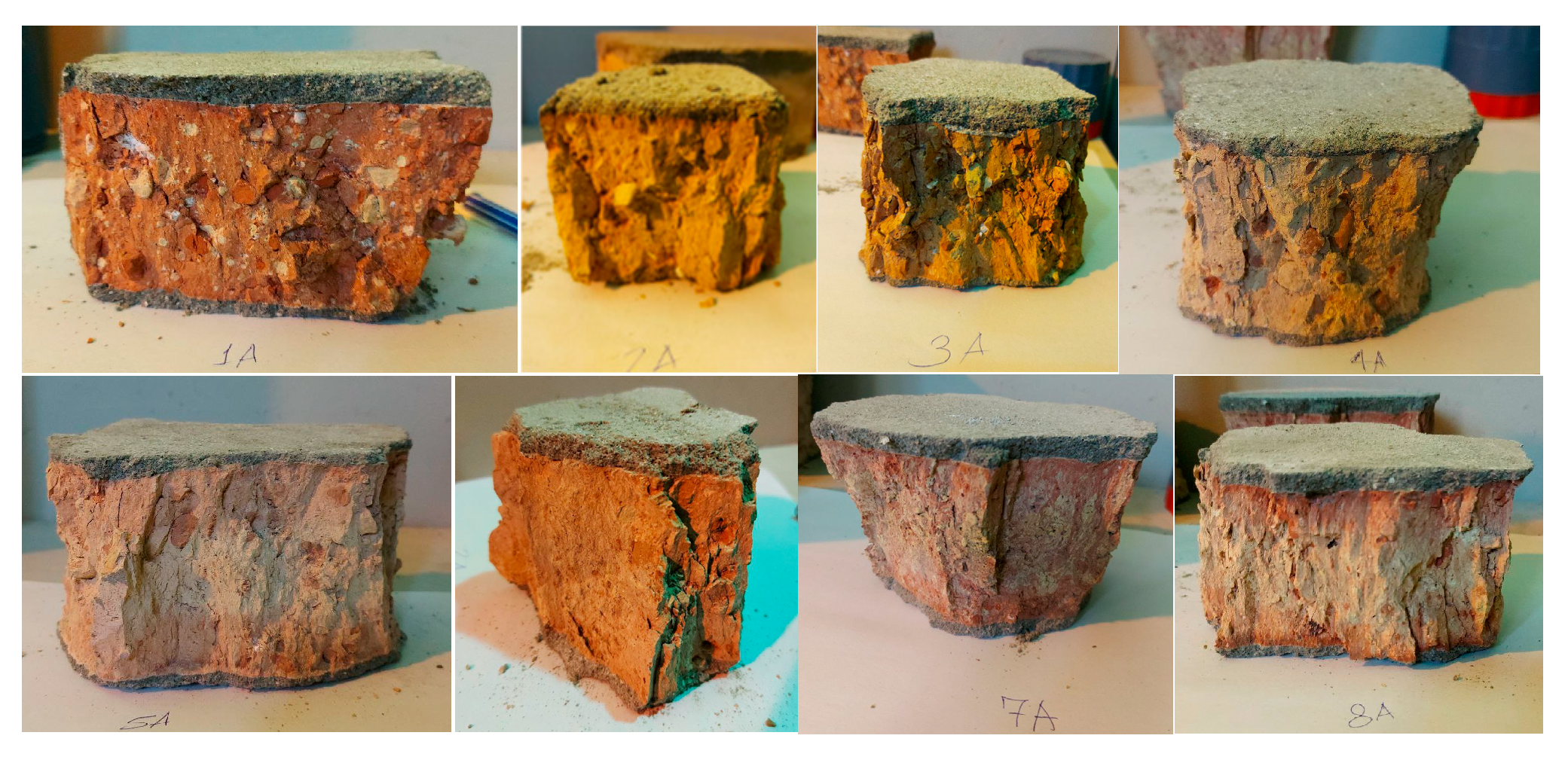
There are no precise data on the bricks (their raw material and/or production) because of their age. Either no such documentation was made, or these records are no longer available. Therefore, it is advisable to rely on the available architectural history of other buildings of a similar period built on a nearby building site. Since the Buda Castle was a prominent site in the past, we can assume that the fired clay elements for the construction were carefully planned and, in accordance with the conventions of the time, manufactured on the building site and that care was taken to ensure the quality of the bricks. Elements of unsatisfactory quality were not incorporated into, or used for, this building. In the 18th century, there were several clay mines in Budapest with similar and high-quality clay raw materials. Quartz sand suitable for making masonry elements was available nearby on the Danube bank in Budapest (in Kelenföld). The production of the elements was carried out locally at that time, on a building site of that size. This can be seen in the internal microstructure of the bricks (Figure 1).
It is highly inhomogeneous (with a lot of large grains), but steadily in the volume of the element, indicating manual molding and manual compaction. This is confirmed by the typical light color. On visual inspection, the firing is also uniform, meaning that it was fired in a smaller kiln. It is certain that no Hoffmann kiln or clamp kiln was used. In the mid to late 18th century, several castles were built in the vicinity of Budapest using a similar method, and some of the original construction documents are available. We performed stoichiometry on the 18th century samples (that can be seen in Table 1) and as a comparison we added the stoichiometry of a new brick sample.
The bricks of the historical building were divided into two groups according to their size (Table 2). The larger elements had a nominal size of 295 × 145 × 65 mm and the smaller elements 250 × 120 × 65 mm. The larger bricks have a slightly lower density and slightly higher water absorption capacity than the smaller bricks (Table 2), but this difference is not considered significant enough to treat the two types of bricks as separate types.
The specimens are cut into smaller dimensions, which is approximately 100 × 120 mm, by a girder cutting machine before the test is carried out in order to make it fit on the compression machine plate and this is a suggested size according to the standard EN 772-1 [2]. As a result of this, we have two types of faces on each specimen, one is the original and the other one is the cut face. The physical properties of these specimens are found in Table 2 and Table 3.
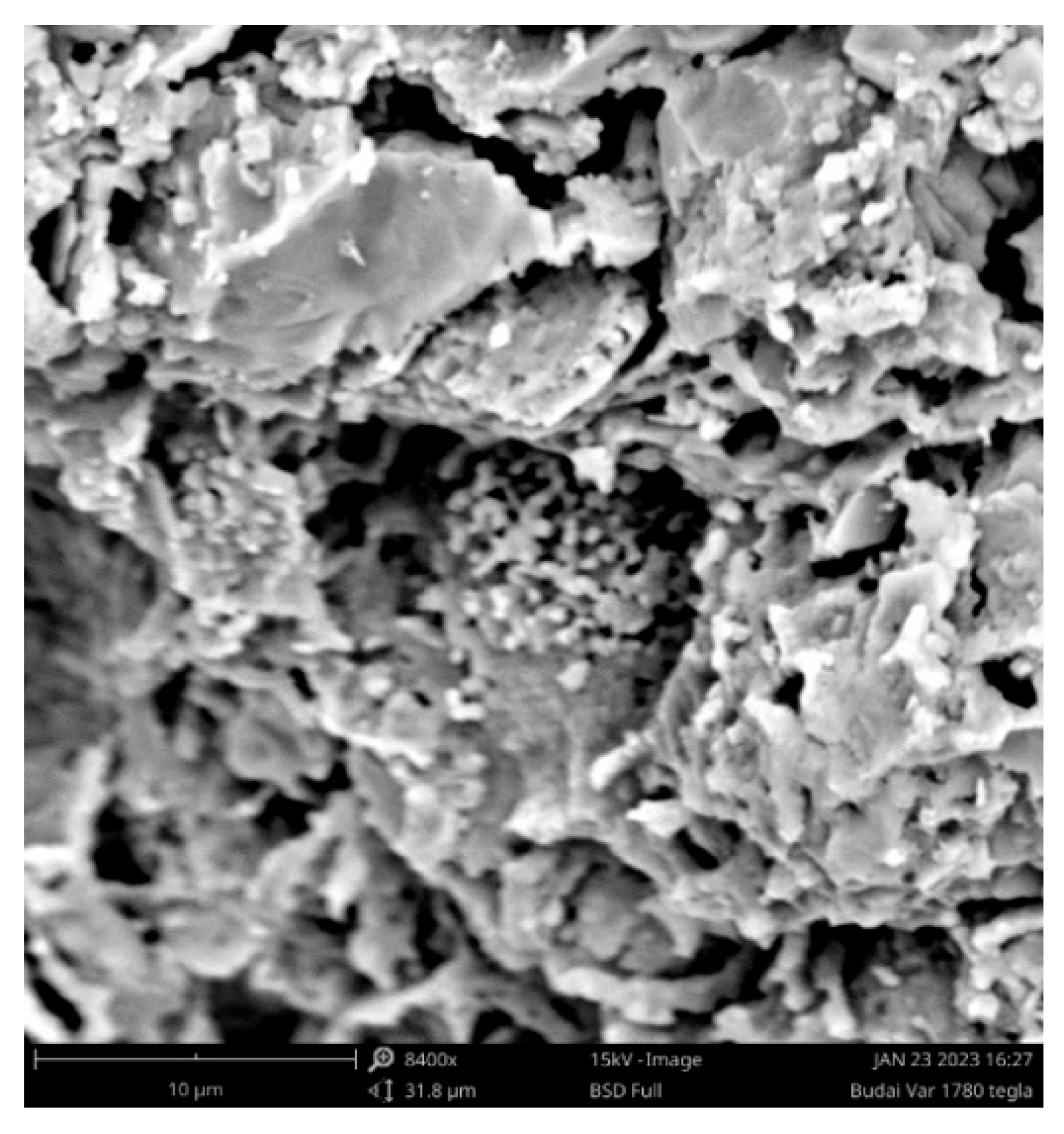
The scanning electron microscope (SEM) images show that the internal structure of the tested historic brick elements (Figure 2) is similar to the modern bricks (Figure 3), a new small solid brick produced in a tunnel kiln in 2018 and stored outside since then). The chemical composition is also similar: clay and quartz sand. There is no sign of using limestone as an additive material.

2.2. Testing Methods

The most suitable method of obtaining the correlation between compressive strength of brick and rebound value is to test the brick using compression testing machine as well as using rebound hammer simultaneously. First, the rebound value of brick is taken and then the compressive strength is tested on compression testing machine. The apparatus used for the estimation of compressive strength are N-type original Schmidt Rebound Hammer and the standard compression testing machine.
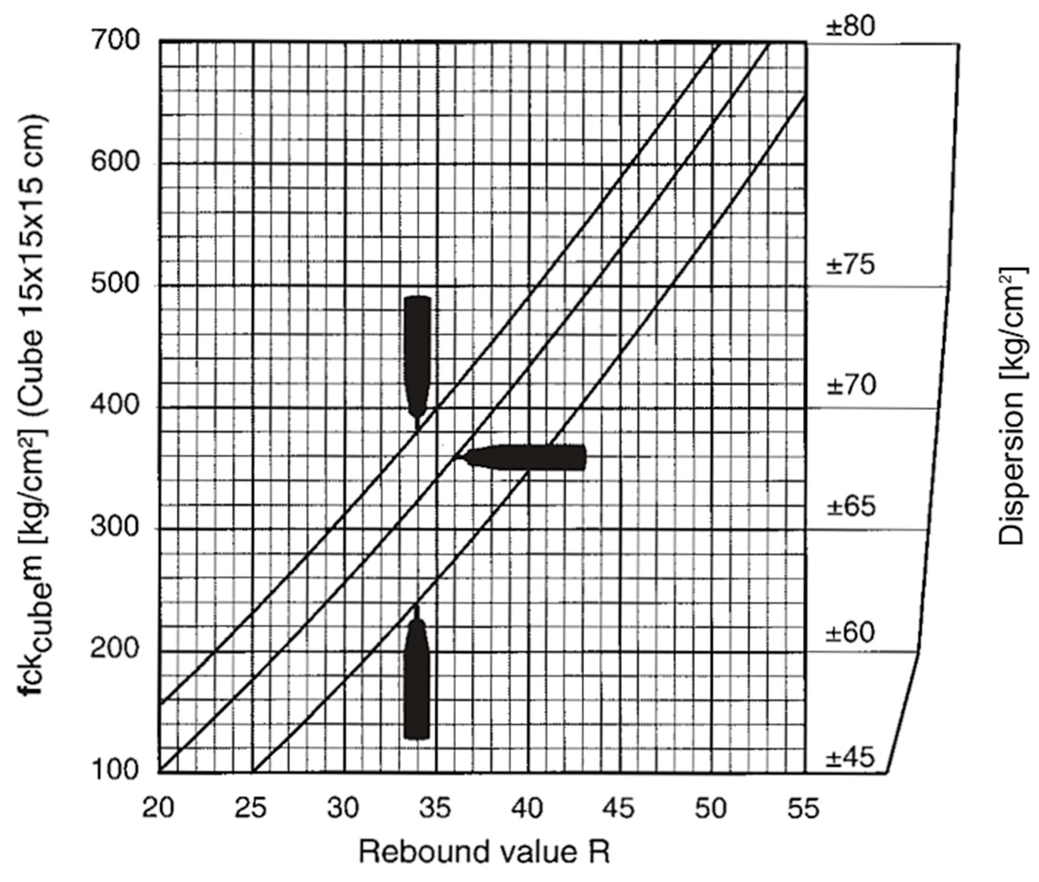
Rebound hammer test method is based on the principle that the rebound of an elastic mass depends on the hardness of the brick surface against which the mass strikes. When the plunger of rebound hammer is pressed against the brick surface, the spring-controlled mass in the hammer rebounds. The amount of rebound of the mass depends on the hardness of brick surface [4]. Thus, the hardness of brick and rebound hammer reading can be correlated with compressive strength of concrete. The rebound value is read off along a graduated scale and is designated as the rebound value or rebound index. The correlation between rebound value and compressive strength is established based on the characteristic curve (Figure 4) developed for 150 mm cube size concrete with modification to fit the clay brick properties.
After reading of compressive strength from Figure 4 using the average rebound value, the calculation of compressive strength of the solid clay brick is carried out by the following empirical equation.
f c k B i r c k   i n   M P a = f c k c u b e k g / c m 2 × 9.81 10 2 V o l u m e b i r c k m m 3 150 3
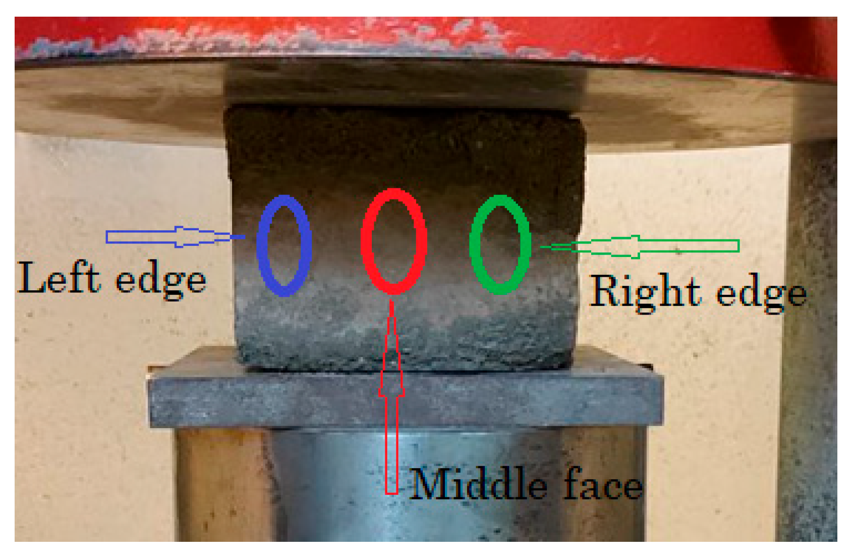
Procedure for rebound hammer test on solid clay brick element starts with calibration of the rebound hammer. For this, the rebound hammer is tested against a test anvil made of steel having Brinell hardness number of about 5000 MPa [11]. After the rebound hammer is tested for accuracy on the test anvil, the rebound hammer is held at right angles to the surface of the concrete structure for taking the readings. The test thus can be conducted horizontally on a vertical surface and vertically upwards or downwards on horizontal surfaces. The points of impact on the specimen must not be nearer an edge than 20 mm and should be not less than 20 mm from each other. The same points must not be impacted more than once [12]. In this investigation, the rebound hammer test was conducted horizontally on all (four) vertical sides’ surfaces of the specimen, at the middle face, right, and left edges of all as shown in Figure 5. Before the rebound hammer test, each specimen is placed in a compression testing machine (FORMTEST ALPHA 3-3000) and a load of 10% to 15% of the estimated compressive strength [13] is applied that is sufficient to stop the specimen from moving during the rebound test.
The results of the rebound hammer test are arranged as follows:
(a)
from all locations of the specimen on original and cut faces,
(b)
from all locations of the specimen on original face only,
(c)
from all locations of the specimen on cut face only,
(d)
from middle face of the specimen on original and cut faces,
(e)
from middle face of the specimen on original face only,
(f)
from middle face of the specimen on cut face only.
For the results obtained from all locations, the average rebound number is calculated by excluding the largest and smallest rebound values [2], but in the case of the middle face, the average rebound hammer is taken as the mean of the results.
After the rebound hammer test, the standard compression test was performed on each specimen as per EN 772-1:2011 + A1:2015 [2]. A thin compensating layer of a cement mortar is provided at the top and the bottom of the specimen to ensure that the load distribution faces of the specimens are flat and parallel to one another and at right angles to the main axis of the specimen. When the specimen is put into the testing machine, the mortar used for this purpose shall achieve at least the same strength as the mortar in the masonry at the time the masonry is tested. The load applied gradually without shock and continuously at the rate of 0.15 MPa/s for the estimated compressive strength between 11 MPa and 20 MPa till the specimen fails [2]. The failure mode (EN 12309-3:2014) of the brick element is taken into account when the results are given. If the brick is unsatisfactory, the test specimen is disregarded.
The compressive strength of masonry perpendicular to the bed joints is derived from the strength of small masonry specimens, tested to destruction. The materials, construction and bonding pattern are required to correspond to those used in practice. In the experiment, the specimens are loaded uniformly in compression. The maximum load (Fmax) achieved is recorded. The compressive strength of masonry is calculated to the nearest 0.1 MPa using the following formula:
f c k ,   i = F i ,   m a x A i
Ai is the loaded cross-section of an individual masonry specimen.
In the case where tests have been carried out on specimens cut from whole units, the normalized strength derived from the test results for cut specimens is that which applies to the whole units from which they were cut. In order to obtain the normalized compressive strength, fb, the compressive strength of masonry units is multiplied by a shape factor (δ), given in Annex A of EN 772-1 [2], wherein the width and height should be determined in accordance with EN 772-16 [14]. The purpose of this test is to validate the rebound hammer test results and check if it is within the confidence limit of ±25% [12].

3. Results and Discussion

3.1. Rebound Hammer Test

The rebound hammer test was carried out on each specimen at the middle face, right, and left edges and the results are recorded in Table 4. Note that, at the face where it is damaged, the test was omitted for that point to avoid a misleading result.
The average rebound value for each specimen based on the location and face types is summarized in Table 5.
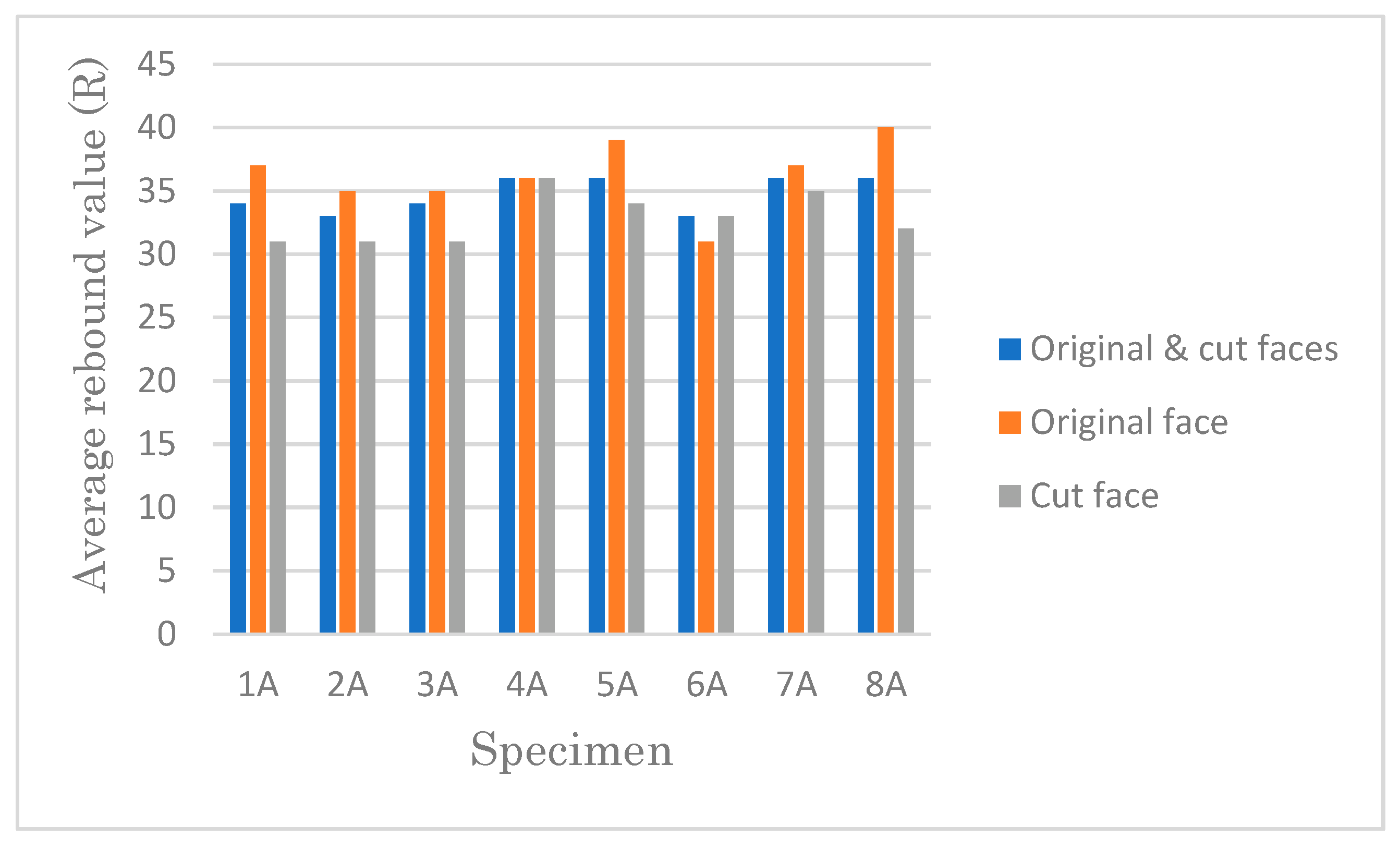
The average rebound value obtained from all locations varies with face types except in specimen 4A (Figure 6).
In addition, the rebound value calculated from the cut face is less than that of the original face, except at specimen 6A (Figure 6), and one of the possible reasons to have lower results when compared to the original face is surface damage during cutting of the specimen at the microstructure level.
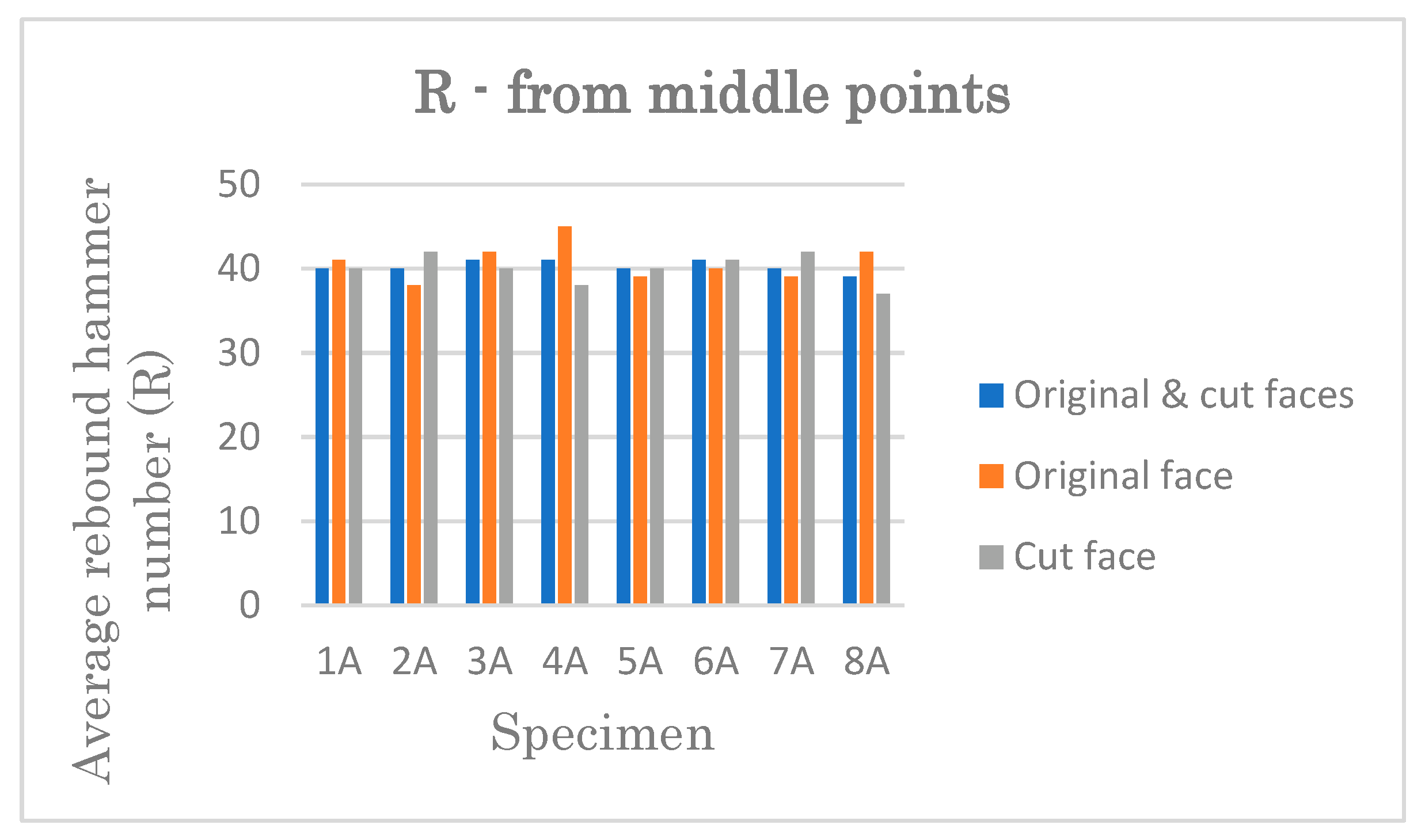
In the case of average rebound value obtained from middle points, the influence of face type is not significant due to the closeness of the results except for specimen 4A (Figure 7).
In general, the rebound value obtained from middle point is high except for specimen 8A in the case of (b). The correlation between rebound value, which is obtained from middle point regardless of face types and case (b), and the compressive strength is established based on the characteristic curve and empirical equation outlined in Section 2.2 (Table 6).

3.2. Standard Compression Test

All eight specimens passed satisfactorily the standard compression test (Figure 8) and their results are found in Table 7.
The compressive strength of masonry units has been converted to the nominalized mean compressive strength of an equivalent 100 mm cube masonry unit according to EN 772-1 [2] after obtaining the compressive strength from the standard compression test. For calculation simplicity, the length has been taken as 100 mm long approximately for all specimens while considering the rest dimension as width and height to obtain nominalized mean strength.

3.3. Comparative Study of the Test Results

After rebound hammer and standard compression tests are conducted for the same specimen, the next step is to compare their results with each other and to facilitate this, the test results are summarized in Table 8.
The estimated compressive strength from all points of the original face (b) is the least convergent to the normalized mean compressive strength, see Figure 9.
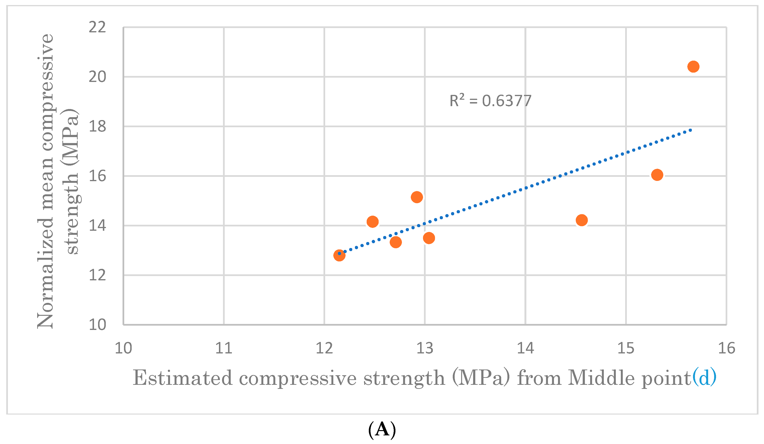
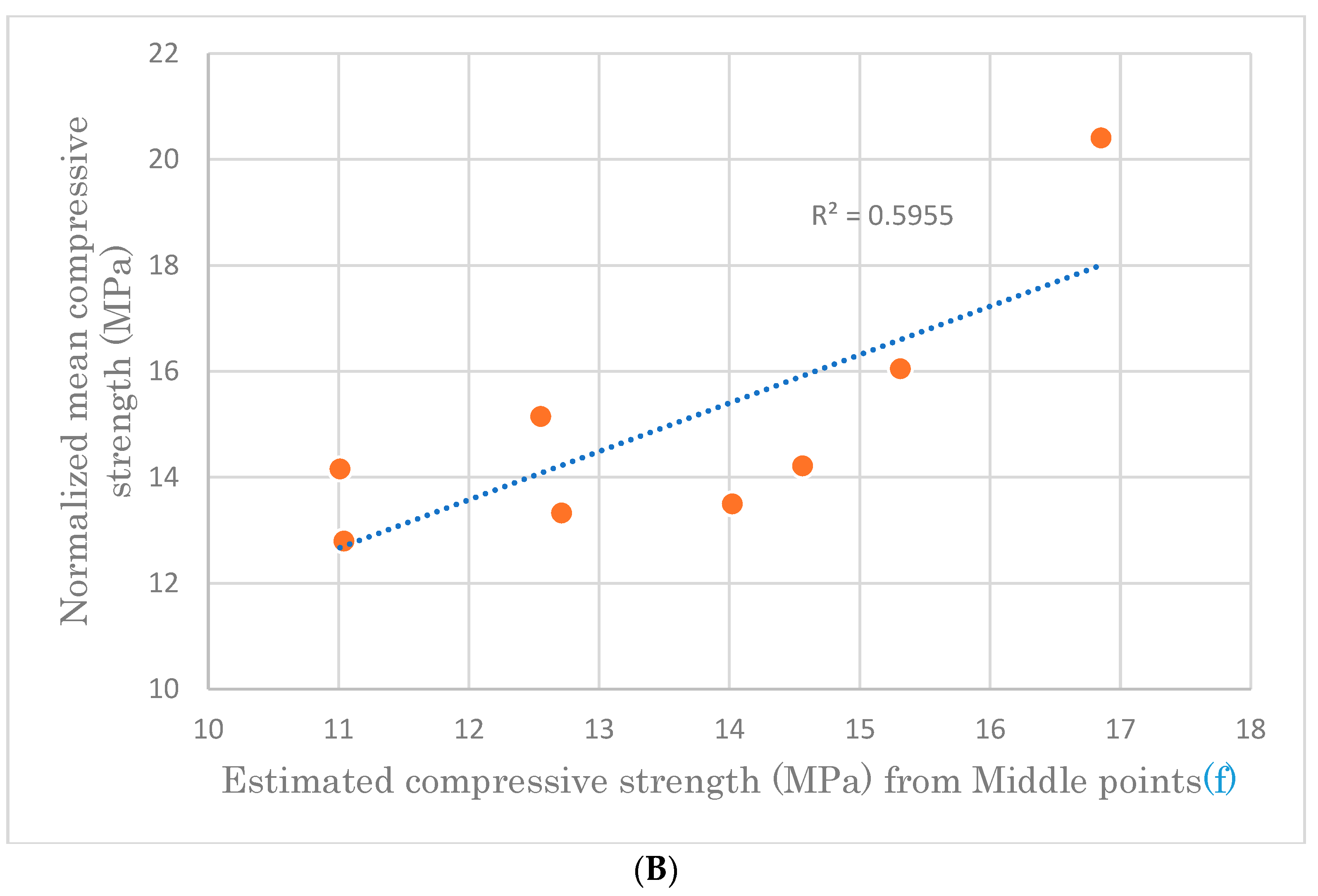
The relationship between estimated compressive strength for middle points with itself and normalized mean compressive strength are established according to their linear correlation coefficients (R2), which are found in Figure 10 and Figure 11.
Figure 10 shows that the estimated compressive strength obtained from case (d) is much closer to case (f) than case (e). This leads to the rejection of the estimated compressive strength obtained from case (e).
Figure 11 shows that the compressive strength obtained from case (d) is the closest one to the normalized mean compressive strength.
According to EN 12504-2 [12], it is unlikely that 95% confidence limits on the estimation of the strength of normal concrete in situ will be better than ±25% under ideal conditions. So, the percentage error of the estimation rises from the rebound hammer test for all and middle points on the specimen face is calculated to check whether it satisfies this condition, and the results are summarized in Table 9.
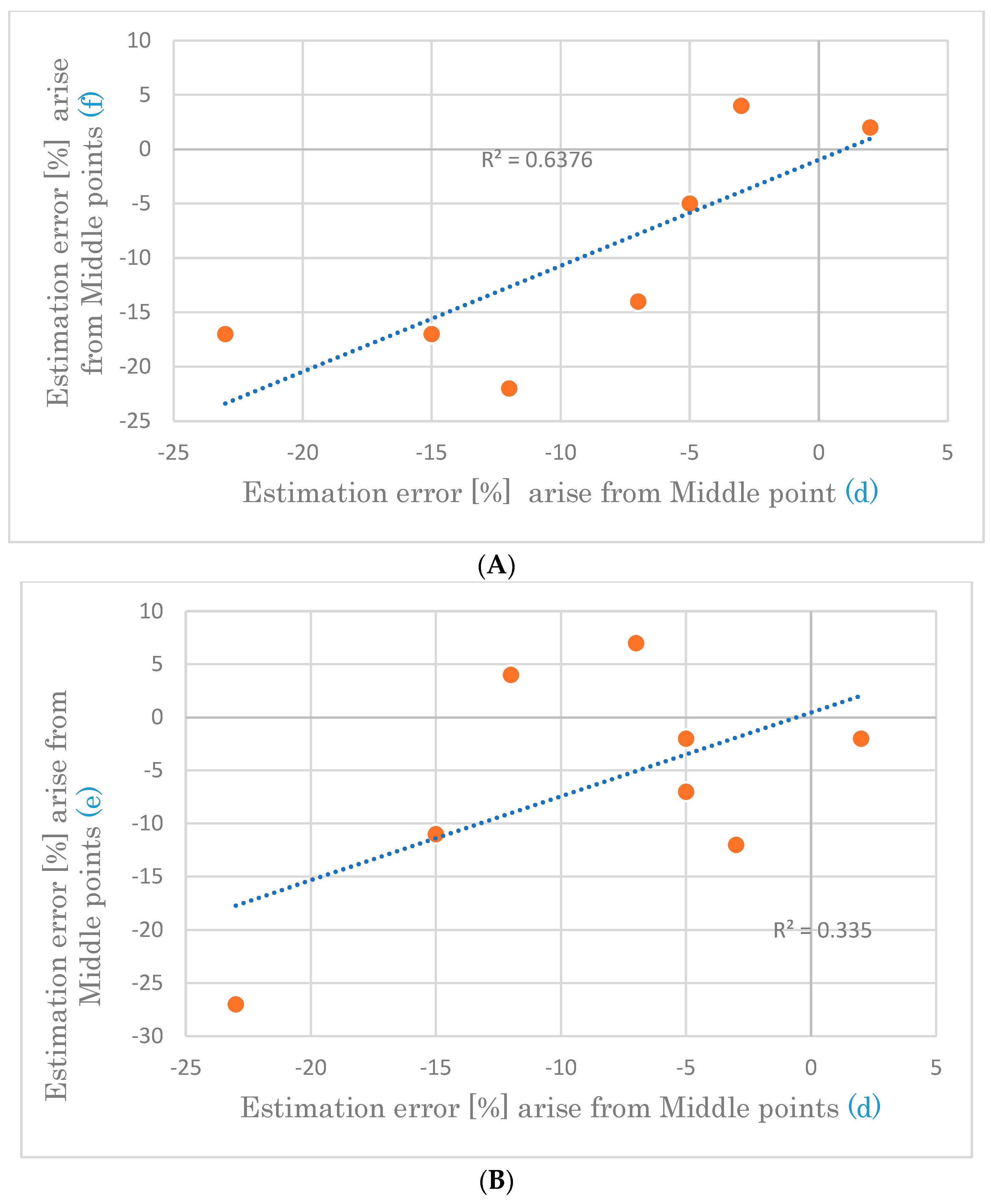
The one that deviates most from the confidential limit by far is the estimated compressive strength from all points (b). The rest of the points are graphically depicted each other to identify their relationship as shown in Figure 12.
The error introduced during the estimation of compressive strength has uniformity in the case of (d) and (f), but not in the case of (e).
Overall, the results show that an accurate estimation of the compressive strength can be achieved by taking the rebound hammer test at middle points of the specimen regardless of the face types.

4. Conclusions

The following conclusions are drawn from this study:
  • The average rebound value obtained from all locations varies with face type except in specimen 4A.
  • The rebound value from cut face is lesser than original face value except at specimen 6A.
  • In the case of average rebound value obtained from middle points, the influence of face type is not significant due to the closeness of the results except for specimen 4A.
  • The estimated compressive strength from all points of original face is the least convergent to the normalized mean compressive strength.
  • The compressive strength obtained from case (d) is the closest one to the normalized mean compressive strength.
  • The estimation error of compressive strength at the middle face is within and around the confidence limits of ±25%.
  • An accurate estimation of the compressive strength can be achieved by taking the rebound hammer test at the middle points of the specimen regardless of the face type.

Author Contributions

Conceptualization, R.N.; methodology, R.N.; software, G.M.M.; validation, R.N; formal analysis, G.M.M. and Z.G.; investigation, G.M.M. and R.N.; resources, G.M.M., Z.G. and R.N.; data curation, R.N.; writing—original draft preparation, G.M.M. and R.N.; writing—review and editing, Z.G.; visualization, G.M.M.; supervision, R.N.; project administration, R.N.; funding acquisition, R.N. All authors have read and agreed to the published version of the manuscript.

Funding

This research received no external funding.

Data Availability Statement

All data from the study can be read in the paper.

Conflicts of Interest

The authors declare no conflict of interest.

References

  1. Brozovsky, J.; Zach, J.; Brozovsky, J., Jr. Determining the strength of solid burnt bricks in historical structures. In Proceedings of the 9th International Conference on NDT of Art, Jerusalem, Israel, 25–30 May 2008. [Google Scholar]
  2. EN 772-1:2011; Methods of Test for Masonry Units—Part 1: Determination of Compressive Strength. European Committee for Standardization: Brussels, Belgium, 2011.
  3. Aliabdo, A.A.E.; Elmoaty, A.E.M.A. Reliability of using nondestructive tests to estimate compressive strength of building stones and bricks. Alex. Eng. J. 2012, 51, 193–203. [Google Scholar] [CrossRef] [Green Version]
  4. Malhotra, V.M.; Carino, N.J. Handbook on Nondestructive Testing of Concrete, 2nd ed.; CRC Press: New York, NY, USA, 2004. [Google Scholar]
  5. Roknuzzaman, M.; Hossain, M.B.; Mostazid, M.I.; Haque, M.R. Application of rebound hammer method for estimating compressive strength of bricks. J. Civ. Eng. Res. 2017, 7, 99–104. [Google Scholar]
  6. Brozovsky, J. Implementation of non-destructive impact hammer testing methods in determination of brick strength. Adv. Build. Mater. Sustain. Archit. 2012, 177, 280–285. [Google Scholar]
  7. Debailleux, L. Schmidt hammer rebound hardness tests for the characterization of ancient fired clay bricks. Int. J. Archit. Herit. 2019, 13, 288–297. [Google Scholar] [CrossRef]
  8. Brencich, A.; Lątka, D.; Matysek, P.; Orban, Z.; Sterpi, E. Compressive strength of solid clay brickwork of masonry bridges: Estimate through Schmidt Hammer tests. Constr. Build. Mater. 2021, 306, 124494. [Google Scholar] [CrossRef]
  9. Fódi, A. Effects influencing the compressive strength of a solid fired clay brick. Period. Polytech. Civ. Eng. 2014, 55, 117–128. [Google Scholar] [CrossRef]
  10. EN 771-1:2011; Specification for Masonry Units—Part 1: Clay Masonry Units. European Committee for Standardization: Brussels, Belgium, 2011.
  11. Proceq. Original Schmidt Manual of Concrete Test Hammer N/NR—L/LR; Proceq: Zürich, Switzerland, 2002. [Google Scholar]
  12. EN 12504-2:2012; Testing Concrete in Structures—Part 2: Non-Destructive Testing—Determination of Rebound Number. European Committee for Standardization: Brussels, Belgium, 2012.
  13. BS EN 13791:2019; Assessment of In-Situ Compressive Strength in Structures and Precast Concrete Components. European Committee for Standardization: Brussels, Belgium, 2019.
  14. EN 772-16:2011; Methods of Test for Masonry Units—Part 16: Determination of Dimensions. European Committee for Standardization: Brussels, Belgium, 2011.
Figure 1. Internal microstructure of the historical brick.
Solids 04 00005 g001
Figure 2. SEM image of historic brick.
Solids 04 00005 g002
Figure 3. SEM image of a modern brick.
Solids 04 00005 g003
Figure 4. Characteristic curve for concrete and rebound hammer model: N/NR [11].
Solids 04 00005 g004
Figure 5. Location of rebound hammer test.
Solids 04 00005 g005
Figure 6. Average rebound value (R) from all points.
Solids 04 00005 g006
Figure 7. Average rebound value (R) from middle points.
Solids 04 00005 g007
Figure 8. Satisfactory failures of specimen.
Solids 04 00005 g008
Figure 9. Multiple compressive values by specimen.
Solids 04 00005 g009
Figure 10. Relationship between estimated compressive strength from middle points. (A) The correlation of compressive strength at middle points (d) and (e); (B) The correlation of compressive strength at middle points (d) and (f).
Solids 04 00005 g010aSolids 04 00005 g010b
Figure 11. Estimated versus normalized mean compressive strength. (A) Compressive strength at middle points (d); (B) Compressive strength at middle points (f).
Solids 04 00005 g011aSolids 04 00005 g011b
Figure 12. Error in compressive strength estimation. (A) Closeness of estimation error between middle points (d) and (f); (B) Closeness of estimation error between middle points (d) and (e).
Solids 04 00005 g012
Table 1. Stoichiometry results.
Brick from 2018Brick from ca. 1780
Element NumberElement SymbolElement NameAtomic Conc.Weight Conc.Element NumberElement SymbolElement NameAtomic Conc.Weight Conc.
8OOxygen70.3846.958OOxygen75.9755.52
14SiSilicon13.8916.2714SiSilicon14.4618.56
35BrBromine4.7315.7735BrBromine3.8814.18
20CaCalcium4.607.6838SrStrontium1.124.49
26FeIron2.155.0119KPotassium1.672.99
12MgMagnesium2.012.0320CaCalcium1.472.70
38SrStrontium1.314.7812MgMagnesium1.421.58
19KPotassium0.931.52
Table 2. The original specimen’s physical properties.
SpecimenDimension [mm]Dry Mass, md [kg]Dry Density ρd [kg/m3]Wet Mass, mw [kg]Water Absorption, % [10]
w m = m w m d m d × 100 %
LWH
1A250120653.24316633.92521Average = 20.5
2A250120653.18716343.84421
3A250120653.29016873.94720
4A250120653.12216013.75820
5A295145654.14214905.05922Average = 21.5
6A295145654.19915405.11422
7A295145654.00114394.79820
8A295145654.17215005.07622
Table 3. The specimen’s dimensions after cut.
SpecimenDimension [mm]SpecimenDimension [mm]
LWHLWH
1A124.2102.478.75A142.0102.878.5
2A123.4101.581.956A137.1102.583.3
3A119.2103.779.97A144.9103.782.1
4A124.0101.875.68A141.5102.668.9
Table 4. The rebound value at test locations.
SpecimenRebound Hammer ValuesTested Surface Type
Middle FaceRight EdgeLeft Edge
1A392626Cut face
403037Original face
403425Cut face
424032Original face
2A372523Cut face
424326Original face
463032Cut face
342835Original face
3A332627Cut face
403230Original face
463330Cut face
443333Original face
4A363136Cut face
483431Original face
393736Cut face
422936Original face
5A383025Cut face
384234Original face
423335Cut face
403834Original face
6A4230-Cut face
403228Original face
402826Cut face
403325Original face
7A4227-Cut face
383632Original face
423733Cut face
39--Original face
8A343026Cut face
414234Original face
403331Cut face
423940Original face
Table 5. Average rebound hammer values.
SpecimenAverage Rebound Value [R]
Original and Cut FacesOriginal Face OnlyCut Face Only
All Points (a)Middle Points (d)All Points (b)Middle Points (e)All Points (c)Middle Points (f)
1A344037413140
2A334035383142
3A344135423140
4A364136453638
5A364039393440
6A334131403341
7A364037393542
8A363940423237
Table 6. Estimated compressive strength from rebound hammer test.
SpecimenCorrelation between Rebound Value and Compressive Strength
Original and Cut FacesOriginal Face OnlyCut Face Only
Middle Points (d)All Points (b)Middle Points (e)Middle Points (f)
R f c k B i r c k   M P a R f c k B i r c k   M P a R f c k B i r c k   M P a R f c k B i r c k   M P a
1A4012.73711.14113.14012.7
2A4013.03510.13811.84214.0
3A4112.9359.84213.54012.6
4A4112.53610.04514.73811.0
5A4014.63913.93913.94014.6
6A4115.3319.44014.94115.3
7A4015.73713.63915.04216.8
8A3912.24012.74213.73711.0
Table 7. Standard compression test results.
SpecimenDimension [mm]Shape Factor, δCompressive Strength, fc [MPa] Normalized   Mean   Compressive   Strength ,   f b   [ MPa ]   f b = δ f c
WH
1A124.278.70.86115.513.3
2A123.481.950.87615.413.5
3A119.279.90.87617.315.2
4A12475.60.84716.714.2
5A14278.50.82417.314.2
6A137.183.30.85418.816.0
7A144.982.10.83424.520.4
8A141.568.90.78416.312.8
Table 8. Summary of the compressive strength results.
SpecimenEstimated Compressive Strength [MPa]Normalized Mean Compressive Strength [MPa]
Original and Cut FacesOriginal Face OnlyCut Face Only
Middle Points (d)All Points (b)Middle Points (e)Middle Points (f)
1A12.711.113.112.713.3
2A13.010.111.814.013.5
3A12.99.813.512.615.2
4A12.510.014.711.014.2
5A14.613.913.914.614.2
6A15.39.414.915.316.0
7A15.713.615.016.820.4
8A12.212.713.711.012.8
Table 9. Error in estimation of compressive strength.
SpecimenError in Estimation of Compressive Strength [%]
Original and Cut FacesOriginal Face OnlyCut Face Only
Middle Point (d)All Points (b)Middle Points (e)Middle Points (f)
1A−5−17−2−5
2A−3−25−124
3A−15−36−11−17
4A−12−294−22
5A2−2−22
6A−5−41−7−5
7A−23−33−27−17
8A−7−17−14
Disclaimer/Publisher’s Note: The statements, opinions and data contained in all publications are solely those of the individual author(s) and contributor(s) and not of MDPI and/or the editor(s). MDPI and/or the editor(s) disclaim responsibility for any injury to people or property resulting from any ideas, methods, instructions or products referred to in the content.