Article

Practical Use of Measuring the Deflection of Roof Layers in the Assessment of the Stability of Mining Excavations in the Polish Copper Ore Mine “Polkowice-Sieroszowice”

by
Lech Stolecki
1,* and
Krzysztof Szczerbiński
2
1
KGHM Cuprum Ltd., Research & Development Centre, 53-659 Wrocław, Poland
2
KGHM Polska Miedź S.A., 59-301 Lubin, Poland
*
Author to whom correspondence should be addressed.
Mining 2022, 2(1), 13-31; https://doi.org/10.3390/mining2010002
Submission received: 30 November 2021 / Revised: 16 December 2021 / Accepted: 18 December 2021 / Published: 21 December 2021
(This article belongs to the Special Issue Mining Strata Control)

Abstract

:
The paper presents the results of long-term continuous measurements of the deflection of the roof layers in the underground copper mine Polkowice-Sieroszowice, Poland belonging to KGHM Polska Miedź S.A. The measurements were performed with the use of the inclinometric method consisting of continuous registration of changes in the angle of inclination of the roof strata. The measurements were carried out using an inclinometer sensor fixed to the end of a rockbolt in the roof. Measurements presented in the article were made in various regions of the underground mine. The monitoring covered: The exploitation front, machinery chamber and the region of the experimental longwall mining of copper ore. The obtained results proved the usefulness of the developed method in the process of the evaluation of the stability of mining excavations. The sensors were highly sensitive and performed the measurements in a simple way; highly accurate and reliable results were obtained.

1. Introduction

Underground mining of a deposit is accompanied by a continuous process of deformation of the rock mass layers. This phenomenon may be observed both at the level of mining excavations as well as on the ground surface, creating subsidence troughs. In the case of underground workings, the progressing deformation of rock is related to an increase of geomechanical hazards (e.g., rock bursts, collapses, rock and gas outbursts), which significantly decreases the safety of work in underground conditions. One of the common threats observed in Polish copper mines is a loss of workings stability in the form of roof falls. Generally, this phenomenon can be defined as a sudden and uncontrolled fall of roof rocks right into the excavation [1,2,3,4].
Due to a severe risk associated with roof falls, several studies are being carried out to assess the possibility of this type of phenomenon. The scope of these tests includes seismic measurements that allow determining the change of seismic wave propagation parameters depending on the degree of deformation of the rock mass [5], microseismic monitoring [6,7], acoustic emission [8,9,10], measurements of roof layer delamination and displacement using strain gauges [11] and optical fiber [12] and monitoring of electromagnetic radiation [13]. In recent years, attempts have been made to use slope changes to monitor the stability of rock layers, both in underground [14,15] and opencast mining [16,17].
In the case of underground mines owned by KGHM Polska Miedź S.A. the collapse phenomenon is considered to be the spontaneous fall of the roof rocks to the height of the used bolting casing or above that height [18]. Standard evaluation of roof fall risk is based on observation methods including:
  • visual observations of the roof condition,
  • roof layer delamination indicated by roof separation gauges in the form of falling wooden plates,
  • testing of roof layer delamination with the endoscopic examination of roof holes,
  • measuring the load capacity of the rockbolt rod using a dynamometric wrench,
  • observation with the use of wooden wedges of cracks visible on the exposed surface of the roof [19].
In recent years, an inclinometric method has also been tested and applied. This method consists in registering changes in the roof inclination angle using an inclinometer sensor, rigidly attached to the tip of the rockbolt installed in the roof [20]. The article presents the results of the measurements of the deflection of the roof layers carried out in the Polish copper ore mine Polkowice-Sieroszowice owned by KGHM Polska Miedź S.A. The presented research was carried out in various regions of the underground mine. The monitoring covered such areas as: The mining front, the machinery chamber and the area of experimental copper ore mining with the use of continuous miner (longwall system).

2. Characteristics of the Research Object

The deposit areas managed by the Polkowice-Sieroszowice mine are located in Lower Silesia voivodship in south-western Poland. KGHM Polska Miedź S.A. manages one large copper ore deposit, which has historically been introduced into production in stages in separate mining areas. Currently, KGHM Polska Miedź has seven mining areas under the obtained mining concessions. Polkowice-Sieroszowice Mine conducts its basic activity in four mining areas: Polkowice, Radwanice-Wschód, Sieroszowice, Gaworzyce, and in the mining area of Głogów Głęboki-Przemysłowy, where an investment project related to obtaining the concession for exploitation of this deposit is under progress (Figure 1).
Copper ore in the mining areas used by the Polkowice-Sieroszowice mine is polymetallic in nature; apart from copper, silver is another important metal. The copper-silver sulphide mineralization that forms the deposit is characterized by a certain variability and may, in various proportions, include sandstone rocks, shales and carbonate rocks. In the deposit areas at the disposal of the Polkowice-Sieroszowice mine, carbonate and shale ore are dominant, accounting for over 77% of the excavated ore, the remaining 23% is sandstone ore. Figure 2 shows the average lithological profile of copper deposits. The ore is excavated with the use of various versions of room and pillar systems with roof deflection, technically adapted to the local geological and mining conditions. The progress of the exploitation front ranges between 16 m/month and 25 m/month and mainly depends on bed thickness. At the moment copper ore is mined using blasting techniques [21]. In 2020, the mine produced about 12 million tons of ore, which amounted to 191 thousand tons of copper.

3. Materials and Methods

3.1. The Inclinometric Method of Evaluating the Roof Stability

Preliminary research on the inclinometric roof monitoring method was conducted in 2011–2017 and was widely described in the publication [20]. The assessment of roof layer stability is performed using inclinometer sensors (CNSs) and a wireless communication terminal (Elfin, Wrocław, Poland) (Figure 3). The measuring equipment was developed for the inclinometric method. The measuring elements of the tilt sensor are micromechanical silicon elements (MEMS) with a measuring range of −90° to 90°.
The measuring system is placed in a 94 mm × 94 mm × 57 mm rugged box and powered by a 3.6 V. The total weight of the sensor amounts to 300 g. There is an indicator diode in the casing of the sensor. Inclination sensors are measured with a resolution of approximately 0.005°. Data transmission is performed using a communication terminal. The terminal allows configuring the CNS as well as to download data. In underground conditions, the distance between the sensor and the terminal should not exceed 10 m.
Measurements of angle changes are performed in the horizontal plane of the sensor in two perpendicular directions X and Y. Measurements are performed with a pre-set frequency (min. 1 min). During the tests presented herein the sampling rate of one record per sixty minutes was used.
Figure 4 shows a schematic representation of the sensor operation. The sensor assumes positive or negative values depending on the direction of its deflection. As a rule, the sensor axes are oriented in relation to the axis of the excavation. The floor area and the initial slope of the rockbolt’s rod are irrelevant as the measurement is relative.
In the inclinometric method, the so-called criterion for assessing the stability of roof layers was used (Figure 5). It is a curve illustrating the stages of roof destabilization as a function of time and the size of the slope angle change [20].
Based on the collected database a real-time warning algorithm has been developed for operational purposes. This algorithm allows to inform about individual destabilization thresholds [20]. The developed algorithm was implemented into the build-in sensor software. Based on the monitored current measurement results of the slope changes, the occurrence of the second or third phase of destabilization of the roof layers is signaled by a diode built into the casing. The performed validation of the measurement method has shown that the optimal roof monitoring radius is that of approximately 30 m.

3.2. Regions Subject to Observation of Changes in the Deflection of the Roof

The results presented in the article were obtained from three regions related to different functions of the underground mine activity. The monitoring covered:
  • Exploitation front of SI-XI/4 panel,
  • Machinery chamber (KMC) C-30D,
  • The area of experimental mining of copper ore with the longwall system in the A-5/1 panel.
The monitoring in the area of the exploitation front of the SI-XI/4 mining panel was aimed at the evaluation of a roof collapse hazard possibility. The deposit of the area is surrounded by the Rotliegend Sandstones (in the roof) and the Zechstein carbonate rocks (in the floor). The thickness of the deposit was about 2.5 m. The roof consists also of gray and calcareous dolomites with an average thickness of 11 m. Anhydrites with a thickness of 34 to 96 m were deposited above.
Exploitation in the SI-XI/4 panel was carried out by a room and pillar mining system with a roof deflection. The deposit was cut with room and pillars with a basic geometry of 5 ÷ 9 m × 6 ÷ 16 m. The width of the single mining face during the cutting phase is about 7 m while the height of the excavations is dependent on the thickness of the exploited deposit. The length of the exploitation front was about 500 m. Exploitation in the panel was carried out at a depth of about 1000 m. Due to the progress of the exploitation front, the measurement system was modified during the observation phase. The sensors CNS 217, CNS 220, CNS 225 and CNS 228, initially located in the gob area, were moved closer to the deposit cutting line (Figure 6 and Figure 7). On the other hand, CNS 218 and CNS 221 sensors were located at one measuring point throughout the entire measurement period.
According to the definition existing in Polish copper ore mines, heavy machine chambers are long-life underground workings in which the mining crew and machines are constantly present. Still, such workings are located in close vicinity to active mining panels and are subjected to the seismic load occurrence in the form of blasting waves or mining tremors. Therefore, in order to provide safe working conditions, a real-time measurement system allowing for quick and reliable information about increasing thread of potential excavation instability is required. The pace of decision making is one of the factors affecting the safety of the working crew. Therefore, in this particular case, a modified measurement system was installed that enables on-line communication. Sensors installed in the excavations are connected by a teletechnical line with a concentrator. This device monitors the operation of the measuring system, collects the data, and if needed, sends it to concerned persons. In the central part of the KMC C-30D chamber, three sensors were installed on the two measuring stations (Figure 8). Two sensors are installed on the first stand, one on the roof of the excavation (1s) and the other on the side of the pillar (1o). The second measuring station was located about 30 m from the first in the adjacent excavation. In this case, one sensor was installed on the roof of the excavation (2s). The sensors were connected to a capacitor (CON) located near the switch enabling it to be connected to the internal LAN of the mine. At the time of the beginning of the observation, the KMC C-30D chamber was located approximately 1800 m from the operational front line of the PO-I field. At the time of the observations, decommissioning works were the primary works carried out in this field. However, in the area of the KMC C-30D chamber, large-size pillars were cut. In Figure 9, these pillars are marked in purple. The monitored chamber was located at a depth of about 750 m.
The deposit in the A-5/1 mining panel was selected with the experimental longwall system with the controlled deflection of the roof with the use of a wooden support stack. The thickness of the deposit in this panel ranged from 0.35 m to 3.2 m (1.6 m on average). The deposit included the lower part of the carbonate rocks (dolomite) and the cuprous shale. The deposit was mined by means of a continuous miner, with the working space secured with powered support (ACT longwall complex). The cross section of wooden stacks was approximately 1 m2 at a pitch of 1 stack per 28 m2 of the exposed roof (Figure 10). Exploitation in the panel was carried out at a depth of about 740 m. The research shows that the excavation with the longwall system was accompanied by periodic, extensive collapses of roof rocks in the excavated space. Due to the experimental nature of this excavation method, measurement systems were installed in the area of the panel, enabling the monitoring of the roof layers. For this purpose CNS inclinometer sensors were used. In the area of the longwall face, three measuring stations were set up. Two stands were located in the headgate (site 1 and site 3), while one site was located in the tailgate (site 2).

4. Results

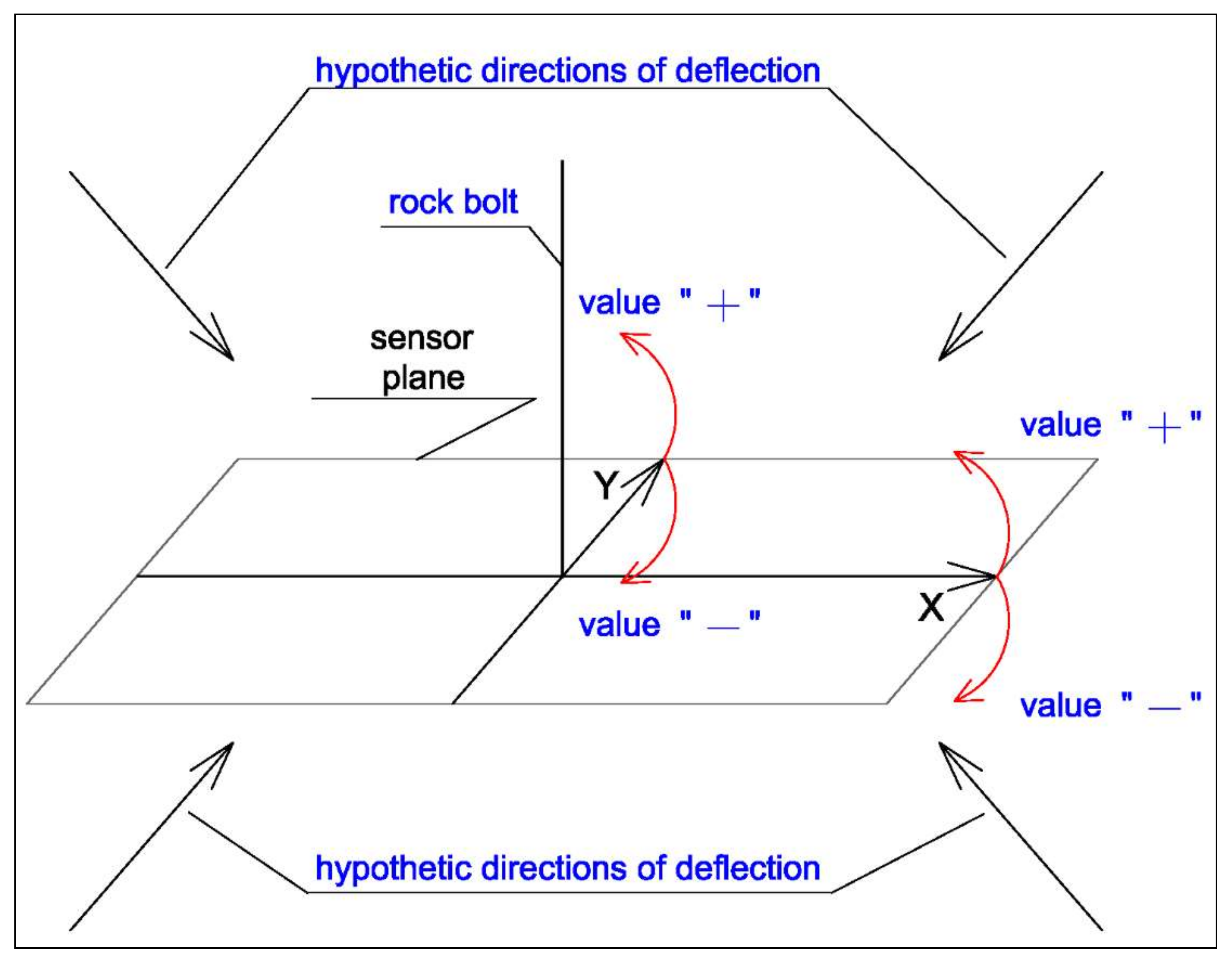
The results obtained with CNS inclinometer sensors installed in the three analyzed locations are presented below. Measurements of the angle changes were made in the horizontal plane of the sensor in relation to the perpendicular X and Y axes with a data sampling of every 60 min. As a rule, the sensor axes were oriented along the axis of the excavations.
Figure 11, Figure 12, Figure 13, Figure 14, Figure 15 and Figure 16 show the measurements of the roof deflection changes observed in the SI-XI/4 panel. The breaks in the measurements visible in Figure 12, Figure 13, Figure 14 and Figure 16 are caused by the lack of observation related to the change in the location of the sensor. The monitoring was carried out between 23 June 2020 and 12 January 2021. Figure 14 shows the monitoring of the measurements obtained with the CNS 227 sensor that ended on 28 November 2020. The completion of the measurements within this period was caused by the reconstruction of the excavation in which the sensor was installed. Depending on the location of the measuring sensor, differences in the changes of the roof inclination were observed. A clear shift in the inclination changes trend on both components was observed on the sensors located in the central part of the panel (CNS 218 and CNS 220). In the case of sensors located on the left side of the panel (CNS 217 and CNS 227), the mining situation in the vicinity of the sensors had an influence on the recorded deflection. The left part of the SI-XI/4 panel borders with the gob area of the SI-XI/3 panel. The deflection of the roof caused by these gobs is visible in the measurements carried out with the CNS 227 sensor. From the beginning of the observation to mid-October, there was a clear deflection of both components due to the progressing process of the SI-XI/4 exploitation panel and the vicinity of the exploited SI-XI/3 panel. After this period, the sensor was installed in a new location.
The location of the sensor between the pillars characterized by larger dimensions (20 × 9 m) than the pillars located in the panel (7 × 9 m) is reflected in the registration of the slope of the roof layers. For the period of about one month (until the completion of the measurements at this stand), the range of registered changes in the roof deflection did not exceed the value of 0.06°. In the case of the CNS 217 sensor, the recorded angle values on both components are approximately constant throughout the observation period. This situation is caused by the “remnant of the deposit” (part of the deposit to be left without operation), in the area in which the sensor has been installed. The analysis of the data recorded with the CNS 217 sensor showed that leaving a part of the deposit without exploitation disturbs the technological process of deflection of the roof layers. Regarding the measurements carried out with sensors located on the right side of the SI-XI/4 panel, it should be noted that the panel borders here with the undisturbed rock mass of the SI-XI/5 panel. Such a mining situation has an impact on the level and nature of the deflection of the roof layers (Figure 6 and Figure 7). On both sensors, the deflection is observed mainly in the Y component (oriented parallel to the line of the exploitation front in the panel SI-XI/4). However, in the case of the X component, a relatively constant level of the recorded values of the inclination angle of the roof layers is observed.
The ranges of the registered changes in the angle of inclination of the roof layers of the entire panel ranged from 0.1° for the CNS 217 sensor (X component) and up to 0.5° for the CNS 218 sensor (X component). The greatest changes were observed in the central part of the mining panel. On the other hand, the smallest deflection was observed on the right side of the panel (sensors: CNS 217 and CNS 227). Measurements obtained with the CNS 221 sensor should be discussed (Figure 11). In this case, changes in the relatively regular decreases of roof inclination were observed. The value of the measured angle was up to approx. 0.05°. The observed changes correlate well with the operation of the mine’s ventilation system. The decrease begins when ventilation is turned off and ends when it is restarted. These activities are related to the weekend or holiday break of the mine’s operation. This phenomenon was also identified in the course of observations carried out using other measurement methods [23,24,25]. The performed analyzes showed that the main factor causing the changes caused by switching off the ventilation system is the location of the sensor in the strong current of air ventilating the excavation. In the case of the CNS 221 sensor, a free-flow fan was installed in its location, the purpose of which was to ventilate the workings located in the area of the faces.
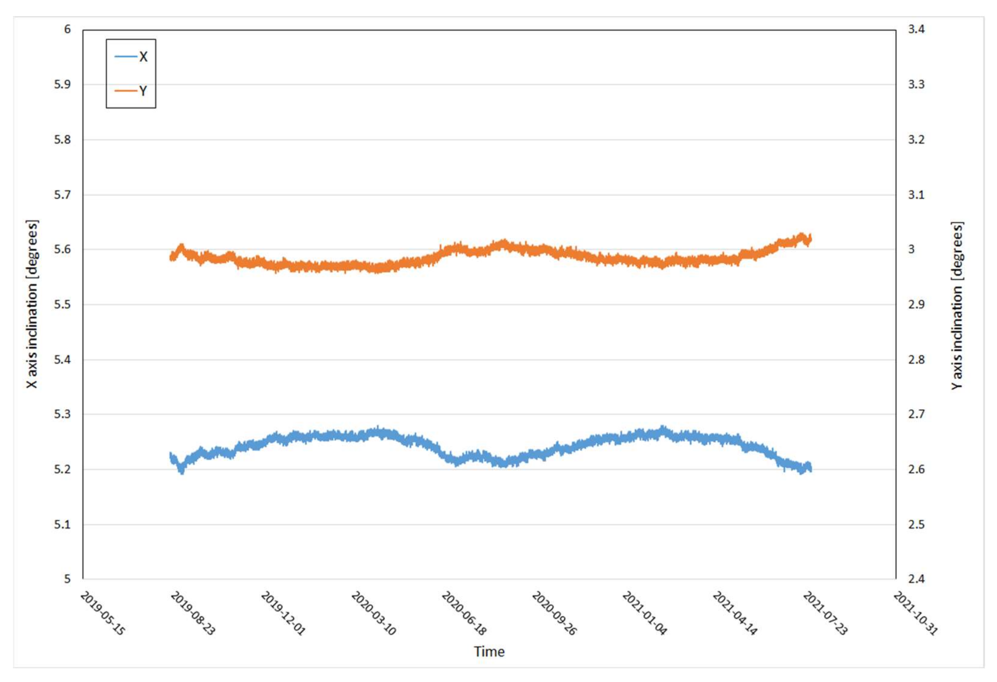
In the case of the measurements carried out at KMC C-30D, the results of the monitoring during the period of 20 August 2019–28 July 2021 are presented. Two locations were included in the observations. The first one covered the excavation located in the central part of the chamber. Two sensors are installed there. One is located on the roof (Figure 17). The second sensor at this work station was mounted on the side of the pillar, in a sandstone rock (Figure 18). Previous experiences from examination of roof deflections show that the deformation process of a mining excavation firstly occur in the sandstone layers [26]. This is due to the much lower compressive strength of sandstone rocks (Rc = 25 MPa) compared to dolomite rocks (Rc = 180 MPa). The second work station (2s) was located on the roof of the excavation, serving as a transport route between KMC and the PO-I exploitation panel (Figure 19). According to the authors, the applied configuration of the measurement system should allow identifying the beginning of the deformation process of the chamber workings caused by the approaching operational front. The analysis of the obtained results showed a clear influence of the seasons on the recorded parameters. The observed changes in the angle of inclination between summer and winter were:
  • in the case of the X component, approximately 0.05°,
  • in the case of the Y component, approximately 0.08°.
Additionally, at work station 2-S, there is a deflection of the roof layers caused by cutting works on large-size pillars (marked in purple, in Figure 8). These pillars were located about 400 m from the measuring station. The registered changes are characterized by a slight but noticeable trend of deflection of both of the components. The range of these changes is 0.15° for the component X and 0.09° for the Y component.
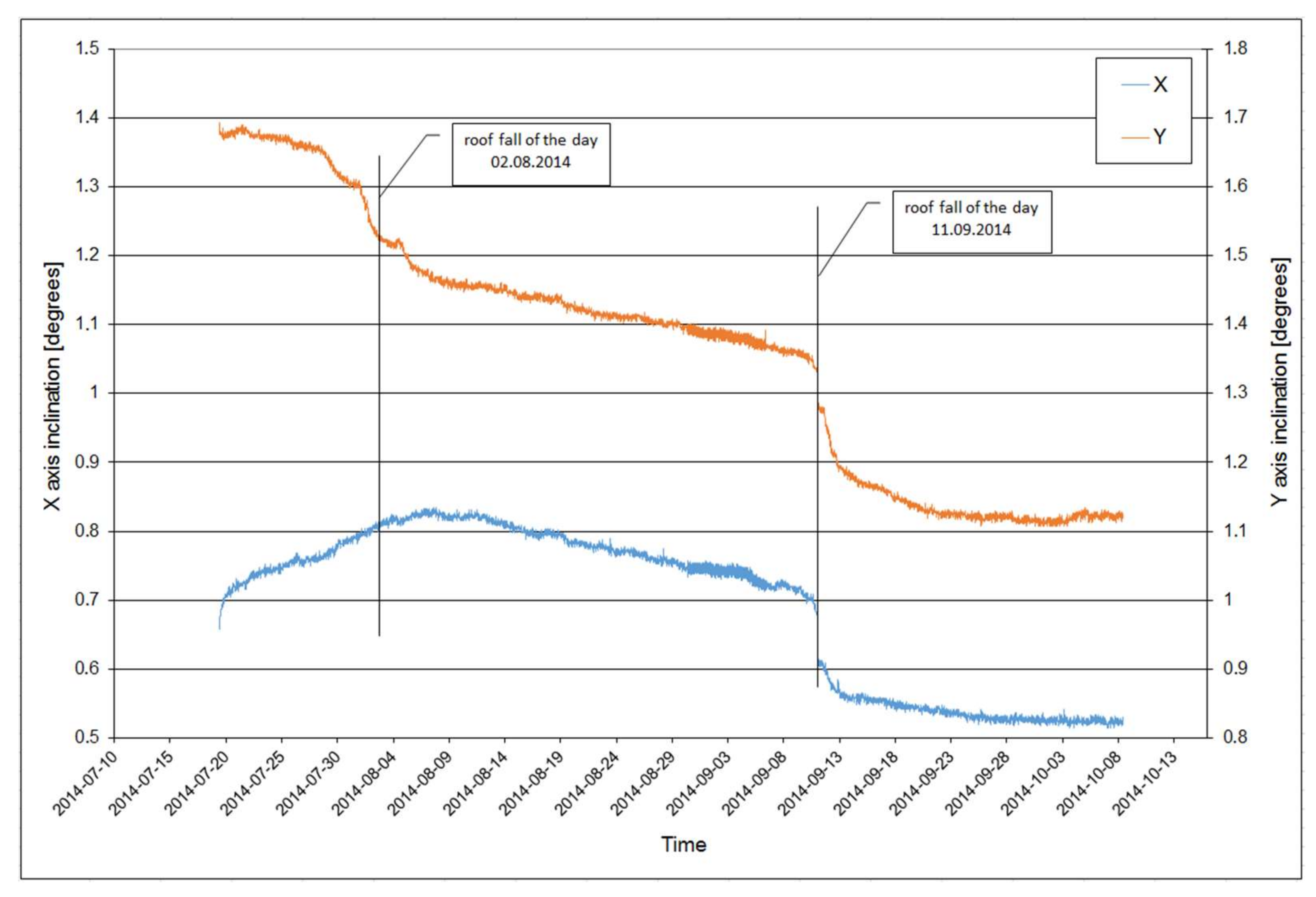
The last observation was related to the monitoring of the roof layers’ deflection within the experimental panel of copper ore exploitation with the longwall system (panel A-5/1). Measurements were carried out at three different stations in a period of 07.2014 to 10.2014 (Figure 10). Stations 1 and 3 were located in the headgate (Figure 20 and Figure 21), while site 2 was built in the tailgate (Figure 22).
The X component was oriented parallel to the workings axis while the Y component was situated perpendicular to it. The ranges of the recorded changes in the angle of inclination are clearly different for both of the components. In the case of component X, the lowest value equal to 0.1° was recorded on work station 1, and the highest—on work station 2, equal to 0.4°. In turn, when analyzing data recorded in the Y direction one may conclude that the highest value of inclination, equal to 0.8° was recorded at station 1. In the case of the remaining two stations, the same value equal to 0.6° was recorded. During the conducted monitoring, in the area of the roof deflection monitoring, there were two roof falls within the excavated area (Figure 10). Figure 20, Figure 21 and Figure 22 (a vertical line) the moment of the roof fall occurrence. The analysis of the obtained data showed that clear changes in the inclination were observed both before and after the occurrences of the roof falls.

5. Discussion

The performed measurements allowed us to obtain a database on the characteristics of roof deflection in various sectors of the underground mine. In the case of measurements carried out in the area of the exploitation front, the impact of the location of the monitoring station and mining conditions on the level of the registered deflection of the roof layers is noticeable. According to the performed analyses, one may conclude that the greatest deflection is observed in the central area of the mining panel, where the impacts related to the deflection caused by the progress of the mining front and the panel width accumulate. In the case of contour galleries, the magnitude of roof inclination is strictly related to local geomechanical conditions and mining situation (vicinity of excavated area, undisturbed rock mass, leaving a part of the deposit unexploited). In the case of sensors installed in the SI-XI/4 panel, the observed changes in the inclination were characterized by a slow and steady trend of inclination changes. During the analyzed period, none of the sensors signaled the deterioration of the conditions of the excavation stability and no such situation took place.
Examples of correlation between the recorded deflections and the occurring cases of roof falls occur in the case of monitoring carried out in the area of the A-5/1 panel. In accordance with the adopted exploitation technology, the periodically occurring falls of the roof layers constituted an excellent testing ground.
The collected material made it possible to identify and characterize the process of the stability loss of the roof layers. The conducted analyses showed that the phenomenon is preceded by a clear acceleration of the process of deflection of the roof layers, occurring in a short period of time, i.e., from a few to up to several days. The level of the registered changes is significantly affected by the location of the sensor in relation to the observed phenomenon.
The performed analyzes showed that the sensors located within 30 m from the roof fall clearly indicate the process of loss of stability. However, in the case of the sensor located far (more than 30 m) from the place of the roof fall, we observe slight changes in the inclination of the roof layers. These changes are caused by a change in the state of stress in the area of the excavation affected by the roof fall.
The inclinometric method to assess the stability of excavations uses two parameters: The value of the registered slope and rate of changes of the measured angles. The results of the performed tests of stability loss of the roof layers leading to the roof fall show that this is a clearly determined phenomenon. It is preceded by a characteristic process of destruction of the roof rocks described using the recorded changes of inclination of the angle of the inclinometer. Three phases of destabilization can be separated in this process, for which duration intervals and measured angle change ranges were determined. This knowledge was the basis for the development of the so-called stability criterion of the roof layers, which in a simplified way reflects the rate of the roof layer destruction process (Figure 5). The obtained time differences of the particular phases mainly reflect a different geological structure of the roof layers and the applied additional protections (e.g., of the hydraulic prop support) or their lack. Regarding the differences in measured inclination angles, the location of the sensor in respect to the center of the collapse has a very large impact on the measured value. For tectonically undisturbed roof surfaces, the maximum monitoring range of the inclinometer is about 30 m. It was found that, depending on the distance between the place of deterioration of the roof stability and the location of the test stand, the range of the measured slope changes will be different. At the same time, analysis of the measurement data has shown that the nature of these changes for sensors installed at different distances from the center of the collapse will be similar. Therefore the values measured in the central zone will be substantially higher than the limit of the sensor monitoring range. The developed criterion of the roof rock destabilization has found practical application in the form of a signaling algorithm implemented in the inclinometer. The sensors have been equipped with a signaling diode, which informs about the present phase in which the working roof is located using an appropriate color. In case of Polish copper ore mines, this is the first, and currently the only quantitative measurement method enabling estimation of the roof collapse risk occurrence [20].
One issue that needs to be discussed is the influence of ambient temperature changes on the measuring system. This phenomenon was observed with the sensors installed in the chamber of KMC C-30D machines. Conducting measurements in one location for a long period of time (about two years) allowed to record data enabling the identification of such a phenomenon. On the other hand, the main factor influencing the registered changes is the location of the measuring stations. Both sites where such changes occurred are located in the fresh air ventilation zone. Additionally, in the vicinity of the analyzed area, there is a ventilation shaft, which supplies fresh air to the mine workings (about 2 km away). Sensors situated in such a way were in the zone of influence of clear, seasonal changes in air temperature. The described changes are not clearly visible in the case of sensors situated closer to the operational front, where large fluctuations in temperature are not recorded [27]. The conducted analyses and experiments related to the implementation of inclinometer measurements allow us to formulate a statement that the identified changes may be caused by two factors. The first one is the influence of the temperature on the accuracy of the inclinometer sensor. Despite the application of the correction taking into account the temperature coefficient (provided by the sensor manufacturer), there is always a small indication error, with which we can deal in this case. In addition, changes in types of used rockbolt to which the sensor is attached should be taken into account as well. In the case of the analyzed locations, there may occur clear, seasonal temperature fluctuations (up to about 15 °C). Such values of temperature fluctuations may contribute to a change in the shape of the rockbolt’s rod described by the coefficients of the linear and volumetric expansion of the steel. These will be small changes (tenths or hundredths of a millimeter); however, it should be noted that the changes observed at the stations located in the area of the KMC C-30D chamber are very small and reach values of hundredths of a degree. Their identification was only possible due to the use of very sensitive measuring devices. In the case of inclinometer sensors (CNS), their measurement resolution is approximately 0.005°.

6. Conclusions

The results of the roof layer deflection measurements presented in the article were obtained in studies carried out in various regions of the underground mine (mining front, heavy machinery chamber, and the area of experimental copper ore extraction with the longwall system). The measurements were carried out in accordance with the assumptions of the inclinometric method consisting of continuous registration of changes in the angle of inclination of the roof strata. The obtained results showed the great usefulness of the inclinometric method in the process of assessing the stability of mining excavations. The use of high sensitivity sensors along with the simple method of carrying out measurements and the high accuracy of the results obtained prove the practical usefulness of this method. At the same time, it is a versatile method that can be used to monitor mine workings with different functions. It should be noted, however, that the methodology for conducting measurements and interpreting measurement data is adapted to the geological and mining conditions of Polish copper ore mines. An attempt to use the inclinometric method to assess the stability of the floor layers in other conditions requires the implementation of appropriate research and development works.

Author Contributions

Conceptualization, L.S. and K.S.; methodology, L.S.; software, L.S..; validation, L.S. and K.S.; formal analysis, L.S.; investigation, L.S.; resources, K.S.; data curation, L.S and K.S.; writing—original draft preparation, L.S.; writing—review and editing, L.S. and K.S.; visualization, L.S. and K.S.; supervision, L.S.; project administration, L.S.; funding acquisition, L.S. All authors have read and agreed to the published version of the manuscript.

Funding

This work was supported by the Polish Ministry of Science and Higher Education (grant number 554/E-578/S/2011) and commercial grant (number B/16/0070).

Data Availability Statement

The study did not report any data.

Conflicts of Interest

The authors declare no conflict of interest. The funders had no role in the design of the study; in the collection, analyses, or interpretation of data; in the writing of the manuscript, or in the decision to publish the results.

References

  1. Chudek, M. Rock Mass Mechanics; Silesian University of Technology Publisher: Gliwice, Poland, 2010. [Google Scholar]
  2. Bajpayee, T.S.; Pappas, D.M.; Ellenberger, J.L. Roof instability: What reportable non-injury roof falls in underground coal mines can tell us. Prof. Saf. 2014, 59, 57–62. [Google Scholar] [PubMed]
  3. Cała, M.; Flisiak, J.; Tajduś, A. The Mechanism of Operation of the Roof Bolt in the Rock Mass of Various Structure; Library of the School of Underground Exploitation Publisher: Kraków, Poland, 2001. [Google Scholar]
  4. Sinha, S.; Chugh, Y.P. Validation of critical strain technique for assessing stability of coal mine intersections and its potential for development of roof control plans. J. Rock Mech. Geotech. Eng. 2018, 10, 380–389. [Google Scholar] [CrossRef]
  5. Maleki, H.; Jung, Y.; Hollberg, K. Case study of monitoring changes in roof stability. Int. J. Rock. Mech. Min. Sci. 1993, 30, 1395–1401. [Google Scholar] [CrossRef]
  6. Sikora, M. Induction and pruning of classification rules for prediction of microseismic hazards in coal mines. Expert Syst. Appl. 2011, 38, 6748–6758. [Google Scholar] [CrossRef]
  7. Will, R.; Smith, V.; Leetaru, H.E.; Freiburg, J.T.; Lee, D.W. Microseismic monitoring, event occurrence, and the relationship to subsurface geology. Energy Procedia 2014, 63, 4424–4436. [Google Scholar] [CrossRef] [Green Version]
  8. Sellers, E.J.; Kataka, M.O.; Linzer, L.M. Source parameters of acoustic emission events and scaling with mining-induced seismicity. J. Geophys. Res. Solid Earth 2003, 108, 24. [Google Scholar] [CrossRef]
  9. Hesser, J.; Kaiser, D.; Schmitz, H.; Spies, T. Measurements of acoustic emission and deformation in a repository of nuclear waste in salt rock. Eng. Geol. Soc. Territ. 2015, 6, 551–554. [Google Scholar] [CrossRef]
  10. Kong, X.; Wang, E.; He, X.; Li, D.; Liu, Q. Time-varying multifractal of acoustic emission about coal samples subjected to uniaxial compression. Chaos Solitons Fractals 2017, 103, 571–577. [Google Scholar] [CrossRef]
  11. Bigby, D.; MacAndrew, K.; Hurt, K. Innovations in mine roadway stability monitoring using dual height and remote reading electronic telltales. In Proceedings of the Underground Coal Operator’s Conference 2010, The Aus IMM Illawara Branch, University of Wollongong, HongKong, China, 11–12 February 2010; pp. 146–160. [Google Scholar]
  12. Zhao, Y.; Zhang, N.; Si, G. A fibre bragg grating-based monitoring system for roof safety control in underground coal mining. Sensors 2016, 16, 1759. [Google Scholar] [CrossRef] [PubMed] [Green Version]
  13. Song, D.; Wang, E.; Li, Z.; Qiu, L.; Xu, Z. EMR: An effective method for monitoring and warning of rock burst hazard. Geomech. Eng. 2017, 12, 53–69. [Google Scholar] [CrossRef]
  14. Zhang, K.; Ji, S.; Zhang, Y.; Zhang, J.; Pan, R. MEMS inertial sensor for strata stability monitoring in underground mining: An experimental study. Shock Vib. 2018, 2018, 1–8. [Google Scholar] [CrossRef] [Green Version]
  15. Ji, S.; Zhang, J.; Pan, R.; Karlovšek, J. Local acceleration monitoring and its application in physical modelling of underground mining. Int. J. Rock Mech. Min. Sci. 2020, 128, 104282. [Google Scholar] [CrossRef]
  16. Ryan, T.M.; Call, R.D. Applications of rock mass monitoring for stability assessment of pit slope failure. In Proceedings of the 33th U.S. Symposium on Rock Mechanics (USRMS), Santa Fe, NM, USA, 3–5 June 1992; pp. 221–229. [Google Scholar]
  17. Carla, T.; Intrieri, E.; Farina, P.; Casagli, N. A new method to identify impending failure in rock slopes. Int. J. Rock Mech. Min. Sci. 2017, 93, 76–78. [Google Scholar] [CrossRef]
  18. Matusz, C.; Szczerbiński, K. Activities aimed at reducing the number of accidents and roof falls at the “Polkowice-Sieroszowice” mine, Cuprum. Sci. Tech. J. 2013, 1, 33–53. [Google Scholar]
  19. Butra, J. Exploitation of the Copper Ore Deposit in the Conditions of Rock Burst and Roof Fall; KGHM Cuprum-CBR Publisher: Wrocław, Poland, 2010. [Google Scholar]
  20. Stolecki, L.; Grzebyk, W. The velocity of roof deflection as an indicator of underground workings stability—Case study from polish deep copper mines. Int. J. Rock Mech. Min. Sci. 2021, 143, 104717. [Google Scholar] [CrossRef]
  21. Polkowice-Sieroszowice. Available online: https://kghm.com/en/our-business/mining-and-enrichment/polkowice-sieroszowice (accessed on 25 August 2021).
  22. Grzebyk, W.; Stolecki, L. Volumetric changes of rock massif preceding mining seismic events. Int. J. Rock Mech. Min. Sci. 2015, 80, 147–154. [Google Scholar] [CrossRef]
  23. Grzebyk, W.; Stolecki, L. Measurements of volumetric changes of a rock mass as an index of rock mass assessment. In Proceedings of the GZN Conference; GIG Katowice: Katowice, Poland, 2013; pp. 423–430. [Google Scholar]
  24. Grzebyk, W.; Stolecki, L. Inclinometric measurements as a tool of monitoring rock mass deformation in underground mines. Bull. Miner. Energy Econ. Res. Inst. Pol. Acad. Sci. 2014, 86, 97–104. [Google Scholar]
  25. Grzebyk, W.; Stolecki, L. Identification of the air ionization phenomenon in mine excavations in terms of the rock mass deformation. Sci. J. Cuprum 2018, 3, 31–41. [Google Scholar]
  26. Grzebyk, W.; Stolecki, L. Reaction of roof-pillar system to the mining process influence in the chamber-pillar technology. Przegląd Górniczy 2016, 72, 37–41. [Google Scholar]
  27. Stolecki, L.; Grzebyk, W. Development of Guidelines for the Use of the Inclinometric Measurement Method to Assess the Stability of Excavation in the Aspect of Roof Fall, Research Work of KGHM Cuprum; KGHM Cuprum: Wroclaw, Poland, 2016; Unpublished work.
Figure 1. Location of the Mining Areas belonging to the Polkowice-Sieroszowice mine.
Mining 02 00002 g001
Figure 2. Geological cross-section of the copper ore in the Fore-Sudetic Monocline [22].
Mining 02 00002 g002
Figure 3. Measurement equipment (the TK communication terminal + the CNS-2 inclinometer) [20].
Mining 02 00002 g003
Figure 4. Operation diagram of inclinometer [20].
Mining 02 00002 g004
Figure 5. Criterion curve of roof layer destabilization [20].
Mining 02 00002 g005
Figure 6. Location of measurement stations against the background of mining excavations at the start of the measurements.
Mining 02 00002 g006
Figure 7. Location of measurement stations against the background of mining excavations at the completion time of the measurements.
Mining 02 00002 g007
Figure 8. Location of the measuring stations in the C-30D chamber.
Mining 02 00002 g008
Figure 9. Location of the C-30D chamber against the background of the workings of the Polkowice-Sieroszowice mine (the moment of starting the measurements).
Mining 02 00002 g009
Figure 10. Location of measurement sensors against the mining situation in the A-1/5 panel.
Mining 02 00002 g010
Figure 11. Changes in the slope (X and Y components) recorded by the CNS 221 sensor in the SI-XI/4 panel.
Mining 02 00002 g011
Figure 12. Changes in the slope (X and Y components) recorded by the CNS 225 sensor in the SI-XI/4 panel.
Mining 02 00002 g012
Figure 13. Changes in the slope (X and Y components) recorded by the CNS 217 sensor in the SI-XI/4 panel.
Mining 02 00002 g013
Figure 14. Changes in the slope (X and Y components) recorded by the CNS 227 sensor in the SI-XI/4 panel.
Mining 02 00002 g014
Figure 15. Changes in the slope (X and Y components) recorded by the CNS 218 sensor in the SI-XI/4 panel.
Mining 02 00002 g015
Figure 16. Changes in the slope (X and Y components) recorded by the CNS 220 sensor in the SI-XI/4 panel.
Mining 02 00002 g016
Figure 17. Changes in the slope (X and Y components) recorded at the first station with the sensor installed in the roof of the excavation (1-S).
Mining 02 00002 g017
Figure 18. Changes in the inclination (X and Y components) registered at the first station with the sensor installed in the pillar side (1-O).
Mining 02 00002 g018
Figure 19. Changes in the slope (X and Y components) recorded on the second station with the sensor built into the roof of the excavation (2-S).
Mining 02 00002 g019
Figure 20. Changes in the inclination (X and Y components) recorded at station 1.1 located in the headgate.
Mining 02 00002 g020
Figure 21. Changes in the inclination (X and Y components) recorded at station 1.3 located in the headgate.
Mining 02 00002 g021
Figure 22. Changes in the inclination (X and Y components) recorded at station 1.2 located in the tailgate.
Mining 02 00002 g022
Publisher’s Note: MDPI stays neutral with regard to jurisdictional claims in published maps and institutional affiliations.

