Article

A Statistically Based Methodology to Estimate the Probability of Encountering Rock Blocks When Tunneling in Heterogeneous Ground

1
Department of Structural, Geotechnical and Building Engineering, Politecnico di Torino, C.so Duca degli Abruzzi 24, 10124 Torino, Italy
2
Department of Mathematical Sciences, Politecnico di Torino, C.so Duca degli Abruzzi 24, 10124 Torino, Italy
*
Author to whom correspondence should be addressed.
Mining 2021, 1(3), 241-250; https://doi.org/10.3390/mining1030016
Submission received: 23 September 2021 / Revised: 20 October 2021 / Accepted: 22 October 2021 / Published: 26 October 2021

Abstract

:
Strong rock blocks embedded in a weaker soil matrix are found in many geological units. When tunneling in ground containing cobbles and boulders, extremely challenging conditions can be encountered. Such inconveniences may be avoided by means of appropriate tunneling methods and cutterhead designs, which require the content, frequency, and size of rock blocks to be predicted as accurately as possible. Several approaches have been developed to estimate the block fraction of heterogeneous geomaterials for excavation. However, the estimation of cobble–boulder quantities both all along the tunnel and only partially embedded within the tunnel face remains a critical issue. This study develops a methodology for the estimation of the probability of encountering blocks partially or totally contained within the tunnel excavation area, wherein the area of intersection with the tunnel face is greater than the given critical values. For this purpose, a statistical approach has been implemented in a Matlab routine. The potential of this code is that it provides extremely useful and statistically based information that can be used for making a more rational choice regarding tunneling technique and in terms of designing a suitable cutterhead in order to avoid technical problems during tunnel excavations in heterogeneous ground. The executable code is provided.

1. Introduction

Heterogeneous geological formations, such as glacial tills, conglomerates, flysches, breccias, melanges, alluviums, and talus deposits, are widespread all over the world and are characterized by strong rock blocks of variable dimensions embedded in a weaker soil matrix [1,2,3,4]. Due to their considerable spatial, lithological, and mechanical variability, the characterization, design, and construction concerning these geomaterials are extremely challenging tasks. Since the 1990s, by performing many laboratory and in situ tests, as well as numerical analyses, significant advancements have been made in understanding how these heterogeneous formations behave [5,6,7,8,9,10,11]. However, improvements are still needed, mainly to reduce the geotechnical and construction risks associated with the presence of rock inclusions in the different engineering works.
Unexpected and expensive difficulties can arise when tunneling in these geomaterials due to the mixed-face conditions [4,12]. Cobbles and boulders can cause technical problems at the heading and excavation chamber, and of the mucking system of a TBM if cutting tools are not capable of comminuting large blocks to small cobble or gravel sizes [13,14,15]. In fact, the content, distribution, dimension, lithology, abrasivity, and strength of cobbles and boulders can induce, among other problems, face instabilities, extraordinary high strains and stresses on the tunnel lining, obstructions or damage to cutter housings, and more rapid wear of cutters, with consequent schedule delays and costs increments [16,17,18,19,20,21].
The risks associated with tunneling in these heterogeneous geological formations mainly depend on the cobble–boulder characteristics but also on the site conditions (i.e., tunnel depth, surface access constraints, settlement limits, etc.), the size and type of the machine (i.e., TBM with or without face access), and the strength and stiffness of the matrix. Different strengths and stiffnesses of the matrix can significantly influence the effectiveness of the cutter type and the breaking mechanism when the cutter penetrates the block (i.e., classical chip formation, boulder plucking by adhesive bond or matrix-bearing capacity failure through going boulder fracturing) [13,14,22,23].
In order to limit the adverse impact of the cobbles and boulders on tunneling, an appropriate TBM type and an adequate cutterhead design (i.e., opening size, shape, etc.) are necessary. This requires careful geologic and subsurface investigations to predict the rock block content, lithology, frequency, and size. Large diameter borings, boulder volume surveys, geophysical methods, geological maps, test pits, and excavations may help in assessing boulder and cobble quantities, as well as their characteristics [2,22,24,25]. Boulder and cobble volume ratios (i.e., the total volume of rock blocks divided by the total excavation volume) may also be evaluated by means of semi-empirical correlations of geologic and volumetric data from previous excavation works in nearby areas (with the same geologic settings). Fractal block-size distributions have been observed by several authors for fractured rock masses, melange formations, and similar rock–soil mixtures containing a few large blocks and a greater number of smaller rock inclusions [26,27,28]. A few probabilistic methods have also been proposed [24,29,30]. Frank and Chapman (2005) developed a mathematical method for the prediction of rock block quantities and frequencies, which characterize the soil to be excavated. In particular, an exponential distribution of the form N = C/Vd was proposed, with N representing the number of clasts of a given size, C a constant dependent on the sample size data, V the size of the blocks being counted, and d a constant correlated with the clast size distribution. Napoli et al. [30] developed a 3D statistical approach to provide an uncertainty factor to adjust the estimated block quantity as a function of the size of the outcrop area investigated. These methods represent extremely valid and useful tools for the estimation of boulder and cobble quantities contained in an entire rock mass.
However, the prediction of the number and position of blocks of different clast sizes that could be encountered during underground excavation works is of utmost importance. In particular, the estimation of boulders that are near the tunnel perimeter or only partially embedded within the tunnel face (i.e., protruding rock blocks) represents a critical issue [2,17,18,24]. In fact, these blocks are much more difficult to cut and more likely to be pushed aside or plucked, and may cause severe impacts, such as significant settlements, mucking system damage, sinkholes, high contact stresses at the cutterhead-ground interface causing lining damage, boring machine stuck, and obstruction or deflection of a TBM shield. Moreover, they may also produce excessive torque and thrust demand and a significant wear (or breakage) of the cutterhead tools, with consequent lower cutting efficiency, more frequent cutter-change intervention intervals, safety risks, and higher costs.
The aim of this study is to develop a statistically based methodology to estimate the probability of encountering blocks partially or totally contained within both the whole excavation area and the lateral extremities of the tunnel when excavating through heterogeneous ground. The blocks to be considered are those for which the area of intersection (with the tunnel face) is greater than a given critical value. This value must be chosen on the basis of the current project characteristics (i.e., geological–geotechnical soil properties, tunnel diameter, etc.) and must correspond to boulder dimensions that may cause technical problems during the excavation work. The possibility of coming across such boulders should be considered when choosing the excavation method as well as for designing an appropriate cutterhead.
For this purpose, a Matlab routine implementing a statistical approach was written. The code allows for different ground conditions to be simulated in order to take the inherent variability of these geological deposits into account. It is based on algorithms that, among others, (i) generate many tunnel configurations composed of populations of 2D circular blocks with random dimensions and positions within a control area containing the tunnel geometry in order to take the inherent spatial and dimensional variability of the heterogeneous formations into account; (ii) check if the blocks generated intersect—totally or partially—the tunnel face; (iii) identify the blocks that are located at the lateral distance furthest from the center of the tunnel; (iv) determine the intersection area of each block and their equivalent diameter; and (v) calculate the average number and probability of encountering rock blocks of different dimensions—up to six size classes—during the excavation work. Although based on conceptually quite simple operations, the code developed in this paper provides (in a very short time) extremely useful and statistically based information that geopractitioners can use for making a more rational choice of tunneling technique and for designing a proper cutterhead in order to avoid damage to cutting tools, obstructions, etc., during tunnel excavations in heterogeneous ground.
The executable open-source code, named PBE_vers1.2, is provided for further research on this topic.

2. The PBE Code

In order to statistically model the spatial and dimensional variability inherent in heterogeneous formations, a specific Matlab code, performing Monte Carlo simulations, was implemented to generate a great number of boulder–ground configurations. As illustrated in Figure 1, each configuration is characterized by a control area of dimension BxH, represented by the square window, containing the blocks and the tunnel section (i.e., the circular region in the center of the control area). The dimension of the control area can be set each time according to the tunnel diameter. A ratio of at least 5 between the side of the control area and the tunnel diameter is suggested to ensure that the control area is representative of the real in situ geological conditions.
The tunnel has a circular shape and its center can be located anywhere within the control area. This allows for the modelling of different geological ground properties in the tunnel section. For example, if blocks are expected to occur only in half of the tunnel section, the center of the tunnel can be positioned on one control area boundary (Figure 2).
For the estimation of cobble–boulder quantities at the lateral distance furthest from the center of the tunnel, the thickness of an internal circular crown must be set. This value represents the distance of the inner boundary of the circular crown from the tunnel perimeter, defining the position of the dotted line in Figure 1. The probability of encountering blocks located inside this tunnel sub-area or that extending past the perimeter (i.e., protruding blocks) is extremely important for the reasons highlighted above.
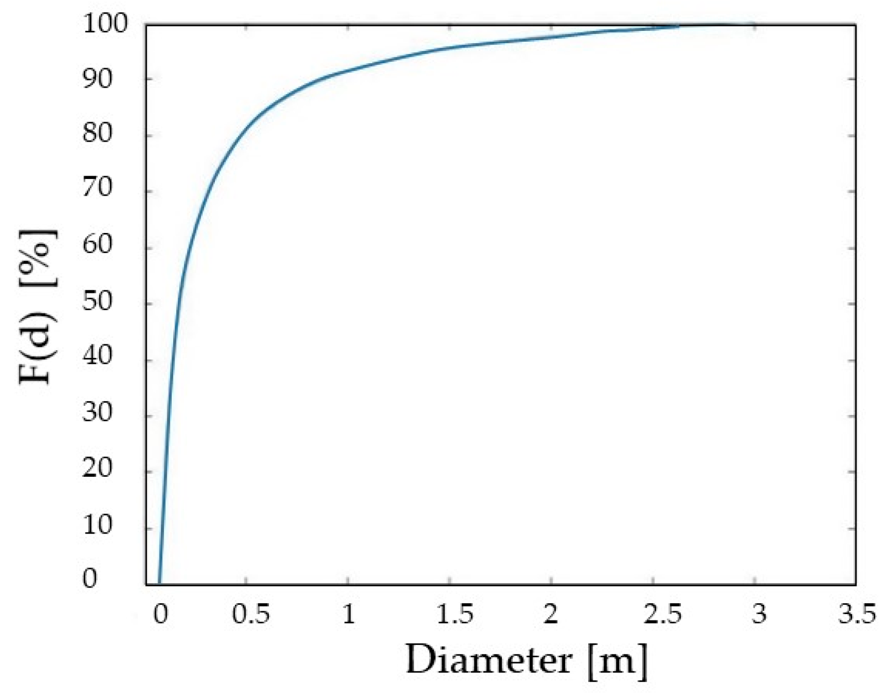
The clasts, represented by circles of variable sizes, are located randomly within the control area. Their number depends on the boulder and cobble volume ratio expected. For each configuration, the code randomly generates n diameters (d) extracted from a population distributed according to the cumulative distribution function of Equation (1), as shown in Figure 3 [31,32], until the block content requested as input is achieved:
F ( d ) = ( a 1 + D d 1 + D ) / ( a 1 + D b 1 + D )
where D is the fractal dimension and a and b are the minimum and maximum expected clast dimensions [31].
Such a distribution properly reflects the grain size distribution of geological units with a block-in-matrix fabric containing a few large boulders and increasing numbers of smaller blocks [33,34]. The parameters a, b, and D of Equation (1) should be estimated on the basis of geological surveys, site observations, and field data, all of which should be as detailed as possible.
Once the n diameters are generated, the code locates the blocks randomly within the control area while avoiding block–block interpenetrations, as this would have no physical meaning. Furthermore, intersections between the blocks and control area boundaries are not allowed either as this would no longer reflect the requested rock content. To these aims, a minimum distance between two clasts and between the clasts and control area boundaries were set and equal to 10 cm.
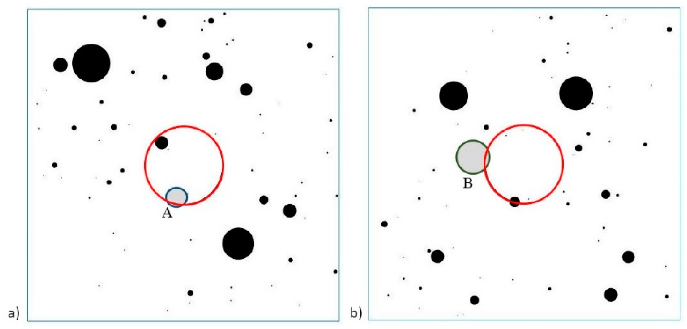
A great number of simulations can be requested in order to achieve a statistical validity of the results. For each configuration generated, the code computes and returns the number and intersection area of all the blocks that are either entirely or partially contained within the tunnel section. Then, the code compares each intersection area with a threshold user-defined value corresponding to the minimum block dimension deemed a possible cause of obstruction or tool damage. If the intersection area of a block (either fully or partially contained within the excavation volume) is smaller than the minimum requested intersection area (i.e., the threshold value), the block is not considered problematic and is discarded from the subsequent analyses (Figure 4).
Furthermore, in order to estimate the probability of encountering cobbles and boulders of different sizes during the excavation, six dimensional categories of intersecting rock blocks (i.e., six equivalent clast areas) can be set. The smallest category corresponds to the previously defined threshold value.
The estimated probability that a certain number, n, of rock blocks (with n = 0, 1, 2, …, 10, >10) belonging to a given size class can be encountered during the tunnel excavation is finally computed by dividing the number of configurations, in which n blocks of that size class were found for the total number of simulations performed. The potential of this new tool is discussed in the next section.

3. Application Example

In order to show the validity of the Matlab routine implemented in the free executable code PBE_vers1.2, the excavation of a circular tunnel in heterogeneous ground was simulated. The parameters required as input are listed in Table 1.
The values assigned in this example to the 16 input parameters can be found as default values in the executable code. The A_thr1 variable corresponds to the minimum requested intersection area (i.e., the minimum block dimension deemed a possible cause of technical problems). Its default value was set as equal to 177 cm2, corresponding to an equivalent circular block fully encapsulated in the tunnel with a diameter of 15 cm, according to [24]. The threshold areas listed in Table 1 define six size classes in terms of equivalent clast diameters: class 1: 15–30 cm (i.e., 177–707 cm2); class 2: 30–50 cm (i.e., 707–1,963 cm2); class 3: 50–75 cm (i.e., 1963–4418 cm2); class 4: 75–100 cm (i.e., 4418–7854 cm2); class 5: 100–150 cm (i.e., 7854–17,663 cm2); and class 6: >150 cm (i.e., >17,663 cm2). All the blocks with an intersecting area smaller than A_thr1 (i.e., 177 cm2, corresponding to an equivalent circular block with a diameter of 15 cm) were not considered further in this study.
In total, 500 configurations were generated in this example in about 4 min. However, since the computation only takes a few minutes, many more configurations can easily be requested and obtained. Moreover, since uncertainties always exist in the determination of some of the input parameters (i.e., BC, a, b, and D), more than a single value may be assumed for each of them and a greater number of analyses can also be performed in a very short time. In this way, by averaging the data obtained, the user can obtain more reliable statistically based results.
Figure 5 shows five of the 500 configurations generated for the example considered, while the probability of finding n intersecting blocks greater than the threshold value, A_thr1, both within the tunnel and at the lateral distance furthest from the center of the cutterhead (i.e., inside the circular crown) is given in Table 2.
What stands out in Table 2 is the high probability of encountering zero blocks (i.e., P_0 blocks was always greater than 49% and up to over 90%). This result is clearly related to the low BC set (i.e., 2%), which produced many configurations without blocks inside the tunnel section (e.g., configuration 1 of Figure 5).
Table 2 also shows that the probability of encountering a single boulder during tunneling (P_1 block) is higher than (or at least equal to) the probability of encountering two (P_2 blocks) or more blocks of the same clast size, regardless of the area examined (i.e., the entire tunnel face or a part of it).
Moreover, for a given number n of blocks, with n ≥1, the highest probability is related to the smallest clast dimension (i.e., equivalent clast diameter in the range 0.15–0.30 m). Furthermore, in the proposed example, a very low probability of encountering blocks during the tunnel excavation was reached for n equal to four and six, while no configuration has more than six intersecting blocks (i.e., PTUNNEL_n≥7 blocks = 0). Conversely, the results obtained for the circular crown of the tunnel indicate that the probabilities of encountering two to four blocks are much lower than those related to the entire tunnel section. Moreover, no configuration had more than four blocks in the sub-area furthest from the center (i.e., PCIRCULARCROWN_n>=5 blocks = 0) and the probability of encountering more than two blocks was very low in the case related to only cobbles belonging to the smallest class dimension.
The executable code also generates other outputs, which are listed and described in Table 3 as text files or JPG images.

4. Discussion and Conclusions

When tunneling in soil containing cobbles and boulders, a number of unfavorable conditions may be encountered related to the size and type of the machine, as well as to the design of its cutterhead. Among other technical difficulties, damage to cutting tools, obstructions, lower penetration rates, and more rapid cutter wear, with consequent delays and extra tunneling costs, may often occur due to the presence of strong rock blocks.
This study provides a statistically based tool for the estimation of the probability of encountering a number n (with n = 0, 1, 2, …, 10, >10) of cobbles and boulders during underground excavations. Specifically, blocks fully or partially located within the entire tunnel section or in a part of it at lateral distance furthest from the center of the cutterhead, have been considered. This information can be extremely useful for making a more rational choice of the tunneling technique and for designing a more suitable cutterhead.
In order to do this, a statistical method implemented in an executable free code is provided. A great number of boulder–ground configurations can be generated according to a given tunnel dimension and location within a control area of rectangular shape, block content, and clast-size distribution. This last input parameter can be estimated using one of the mathematical methods proposed in the literature. The area of intersection between the tunnel face and each block encountered is calculated and compared with a threshold area corresponding to the minimum block size deemed a possible cause of obstruction, tool damage, or other technical problems. Since problematic blocks can be manifold and depend on the excavation method and cutterhead design, up to six threshold values (i.e., size classes) can be set by the user. Finally, the probability of encountering one or more boulders of each size class, in part or in the whole excavation area, is provided. This information can be an extensive and useful tool to predict boulder occurrences all along the tunnel stretch to be excavated within a heterogeneous ground and close to its perimeters in order to appropriately choose the TBM type, including face access, cutterhead design, cutter types, and machine power (i.e., torque, thrust, and speed).
A limitation of the proposed tool is that only circular blocks are considered. Although they may well represent geological units, such as conglomerates and sedimentary melanges, most of the heterogeneous formations generally contain non-spherical rock inclusions. Hence, a future work could address the extension of the PBE code to simulate other block shapes, such as more realistic ellipses.

Author Contributions

Conceptualization, M.L.N. and M.B.; methodology, M.L.N.; software, M.L.N.; validation, M.L.N., M.B. and R.F.; formal analysis, M.L.N.; investigation, M.L.N. and M.B.; data curation, M.L.N.; writing—original draft preparation, M.L.N.; writing—review and editing, M.L.N., M.B. and R.F.; supervision, M.B. and R.F.; project administration, M.L.N. All authors have read and agreed to the published version of the manuscript.

Funding

This research study received no external funding.

Data Availability Statement

The data presented in this study are openly available on Mendeley Data at https://data.mendeley.com/datasets/jjgw7s8yvr/draft?a=d24acd93-5d7c-4bc3-b46a-e5f1280b76da (accessed on 7 September 2021)—doi:10.17632/jjgw7s8yvr.1.

Acknowledgments

The authors thank Eng. Alessandro Cresto from Herrenknecht Italia S.r.l. for the useful discussion on the topic of this research.

Conflicts of Interest

The authors declare no conflict of interest.

References

  1. Jee, W.W.; Ha, S.G. Feasible Boulder treatment methods for soft ground shielded TBM. In Underground Space—The 4th Dimension of Metropolises; Taylor & Francis Group: Abingdon, UK, 2007; pp. 217–222. [Google Scholar]
  2. Hunt, S.W. Tunneling in Cobbles and Boulders. In Proceedings of the Breakthroughs in Tunneling Short Course, Chicago, IL, USA, 14–16 August 2017; pp. 1–46. [Google Scholar]
  3. Dong, W.; Pimentel, E.; Anagnostou, G. Experimental Investigations into the Mechanical Behaviour of the Breccias around the Proposed Gibraltar Strait Tunnel. Rock Mech. Rock Eng. 2013, 46, 923–944. [Google Scholar] [CrossRef] [Green Version]
  4. Marinos, V. Tunnel behaviour and support associated with the weak rock masses of flysch. J. Rock Mech. Geotech. Eng. 2014, 6, 227–239. [Google Scholar] [CrossRef] [Green Version]
  5. Montoya-Araque, E.A.; Suarez-Burgoa, L.O. Automatic generation of tortuous failure surfaces in block-in-matrix materials for 2D slope stability assessments. Comput. Geotech. 2019, 112, 17–22. [Google Scholar] [CrossRef]
  6. Sonmez, H.; Ercanoglu, M.; Kalender, A.; Dagdelenler, G.; Tunusluoglu, C. Predicting uniaxial compressive strength and deformation modulus of volcanic bimrock considering engineering dimension. Int. J. Rock Mech. Min. Sci. 2016, 86, 91–103. [Google Scholar] [CrossRef]
  7. Kalender, A.; Sonmez, H.; Medley, E.; Tunusluoglu, C.; Kasapoglu, K. An approach to predicting the overall strengths of unwelded bimrocks and bimsoils. Eng. Geol. 2014, 183, 65–79. [Google Scholar] [CrossRef]
  8. Xu, Y.; Cai, M. Numerical study on the influence of cross-sectional shape on strength and deformation behaviors of rocks under uniaxial compression. Comput. Geotech. 2017, 84, 129–137. [Google Scholar] [CrossRef]
  9. Coli, N.; Tanzini, M. Characterization of the “Chaotic Complex” (Northern Apennines, Italy). In Rock Mechanics for Resources, Energy and Environment; Taylor & Francis Group: London, UK, 2013; pp. 111–116. [Google Scholar]
  10. Napoli, M.L.; Barbero, M.; Scavia, C. Effects of block shape and inclination on the stability of melange bimrocks. Bull. Eng. Geol. Environ. 2021, 80, 7457–7466. [Google Scholar] [CrossRef]
  11. Napoli, M.L.; Barbero, M.; Scavia, C. Slope stability in heterogeneous rock masses with a block-in-matrix fabric. In Proceedings of the ISRM 2019, Foz do Iguassu, Brazil, 13–18 September 2019; pp. 3482–3489. [Google Scholar]
  12. Kanji, M.A. Critical issues in soft rocks. J. Rock Mech. Geotech. Eng. 2014, 6, 186–195. [Google Scholar] [CrossRef] [Green Version]
  13. Hunt, S.W.; Del Nero, D.E. Two Decades of Advances Investigating, Baselining and Tunneling in Bouldery Ground. In Proceedings of the World Tunneling Congress, Vancouver, BC, Canada; 2010; pp. 1–8. [Google Scholar]
  14. Tarkoy, P.J. The boulder facts of life. In Proceedings of the World Tunneling Congress, Agra, India, 22–24 September 2008; pp. 25–28. [Google Scholar]
  15. Medley, E.W. Bimrocks—Part 2: Case histories and Practical Guidelines. Newsl. Hell. Soc. Soil Mech. Geotech. Eng. 2007, 8, 26–31. [Google Scholar]
  16. Barla, G.; Pelizza, S. TBM tunnelling in difficult ground conditions. In Proceedings of the GeoEng 2000, International Conference on Geotechnical & Geological Engineering, Melbourne, Australia, 19–24 November 2000. [Google Scholar]
  17. DiPonio, M.A.; Chapman, D.; Bournes, C. EPB tunnel boring machine design for boulder conditions. In Proceedings of the Rapid Excavation and Tunneling Conference, Toronto, ON, Canada, 11 June 2007; pp. 215–228. [Google Scholar]
  18. Gwildis, U.; Aguilar, J.; Mosavat, K. TBM Tool Wear Analysis for Cutterhead Configuration and Resource Planning in Glacial Geology. In Proceedings of the North American Tunneling Conference, Washington, DC, USA, 24–27 June 2018. [Google Scholar]
  19. Moritz, B.; Grossauer, K.; Schubert, W. Short term prediction of system behaviour of shallow tunnels in heterogeneous ground. Felsbau 2004, 22, 44–52. [Google Scholar]
  20. Button, E.A.; Riedmueller, G. Shallow Tunneling in a Tectonic Mélange: Rock Mass Characterization and Data Interpretation. In Proceedings of the 5th North American Rock Mechanics Symposium, Toronto, ON, Canada, 7–10 July 2002; pp. 1125–1132. [Google Scholar]
  21. Li, C.; Zhang, D.; Du, S.-S.; Shi, B. Computed tomography based numerical simulation for triaxial test of soil–rock mixture. Comput. Geotech. 2016, 73, 179–188. [Google Scholar] [CrossRef]
  22. Hunt, S.W. Managing Risk of Tunneling in Cobbly, Bouldery Ground. In Proceedings of the TAC 2014: Tunnelling in a Resource Driven World, Vancouver, BC, Canada, 26–28 October 2014. [Google Scholar]
  23. Napoli, M.L.; Barbero, M.; Scavia, C. Tunneling in heterogeneous rock masses with a block-in-matrix fabric. Int. J. Rock Mech. Min. Sci. 2021, 138, 104655. [Google Scholar] [CrossRef]
  24. Frank, G.; Chapman, D.R. A new model for characterizing the cobble and boulder fraction for soft ground tunneling. In Proceedings of the Rapid Excavation and Tunneling Conference, Seattle, WA, USA, 27–29 June 2005; pp. 780–791. [Google Scholar]
  25. Goss, C.M. Predicting boulder cutting in soft ground tunneling. In North American Tunneling; Ozdemir, L., Ed.; CRC Press: Boca Raton, FL, USA, 2002. [Google Scholar]
  26. Nagahama, H. Technical note fractal fragment size distribution for brittle rocks. Int. J. Rock Mech. Geomech. 1993, 30, 469–471. [Google Scholar] [CrossRef]
  27. Riedmüller, G.; Brosch, F.J.; Klima, K.; Medley, E.W. Engineering Geological Characterization of Brittle Faults and. Felsbau 2001, 19, 13–19. [Google Scholar]
  28. Medley, E.W. The Engineering Characterization of Melanges and Similar Block-in-Matrix Rocks (Bimrocks). Ph.D. Thesis, University of California, Berkeley, CA, USA, 1994. [Google Scholar]
  29. Medley, E.W. Uncertainty in estimates of block volumetric proportions in melange bimrocks. In Proceedings of the International Symposium on Engineering Geology and the Environment, Athens, Greece, 23 June 1997; pp. 267–272. [Google Scholar]
  30. Napoli, M.L.; Milan, L.; Barbero, M.; Scavia, C. Identifying uncertainty in estimates of bimrocks volumetric proportions from 2D measurements. Eng. Geol. 2020, 278, 105831. [Google Scholar] [CrossRef]
  31. Napoli, M.L.; Barbero, M.; Ravera, E.; Scavia, C. A stochastic approach to slope stability analysis in bimrocks. Int. J. Rock Mech. Min. Sci. 2018, 101, 41–49. [Google Scholar] [CrossRef]
  32. Barbero, M.; Bonini, M.; Borri-Brunetto, M. Three-Dimensional Finite Element Simulations of Compression Tests on Bimrock. In Proceedings of the 12th International Conference of International Association for Computer Methods and Advances in Geomechanics (IACMAG), Goa, India, 1–6 October 2008; pp. 631–637. [Google Scholar]
  33. Wakabayashi, J.; Medley, E.D.; Wilcox, G.; Risden, C. Tunnels through Fault Rocks and Tectonic Melanges: A Short Course for Engineering Geologists and Geotechnical Engineers; Association of Engineering Geologist: San Francisco, CA, USA, 2002. [Google Scholar]
  34. Medley, E.W. Orderly Characterization of Chaotic Franciscan Melanges. Felsbau 2001, 19, 20–33. [Google Scholar]
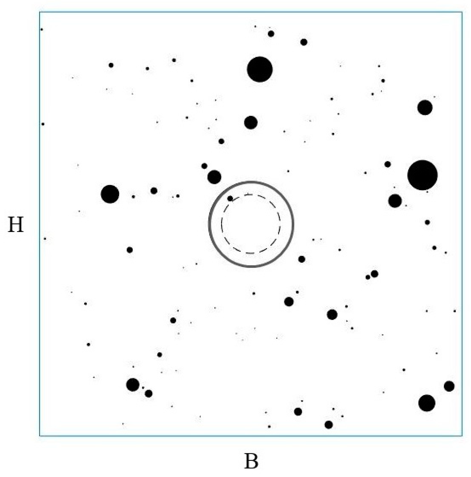
Figure 1. An example of a tunnel configuration in a block-in-matrix formation with a VBP equal to 2%. The length of the control area was set at 5 times greater than the tunnel diameter, indicated with the continuous circle. The dotted line indicates the inner boundary of the tunnel sub-area, where blocks are more difficult to cut and may cause severe impacts, such as higher tool wear.
Mining 01 00016 g001
Figure 2. An example of a tunnel partially located outside the rectangular control area to simulate different geologic units being present in a tunnel section.
Mining 01 00016 g002
Figure 3. An example of a cumulative distribution function (CDF) obtained for D = −1.75, a = 0.075 m, and b = 3 m.
Mining 01 00016 g003
Figure 4. Two tunnel configurations with a protruding boulder (in light gray). (a) The protruding block A has an intersection area greater than the threshold value. Hence, the code classifies it as a possible cause of obstruction. (b) The protruding block B has an intersection area smaller than the threshold value. Since it does not represent a possible cause of obstruction or other technical problems, the code discards it.
Mining 01 00016 g004
Figure 5. Five of the 500 configurations generated with the Matlab code. Different block sizes and positions are shown.
Mining 01 00016 g005
Table 1. Input parameters for the probabilistic analysis.
ParameterVariableAssigned Value
Length of the control area[m]B32.5
Height of the control area[m]H32.5
Tunnel radius[m]R_t3.25
Circular crown thickness[m]R_ext0.8
Tunnel x–y coordinates[m]coord_tB/2 =16.25
H/2 =16.25
Threshold area class 1
(equivalent diameter of 0.15 m)
[m2]A_thr10.0177
Threshold area class 2
(equivalent diameter of 0.3 m)
[m2]A_thr20.0707
Threshold area class 3
(equivalent diameter of 0.5 m)
[m2]A_thr30.1963
Threshold area class 4
(equivalent diameter of 0.75 m)
[m2]A_thr40.4418
Threshold area class 5
(equivalent diameter of 1 m)
[m2]A_thr50.7854
Threshold area class 6
(equivalent diameter of 1.5 m)
[m2]A_thr61.7663
Block content[-]BC0.02
Minimum expected clast dimension [m]a0.075
Maximum expected clast dimension [m]b 3
Fractal dimension[-]D−1.75
Number of configurations to generate[-]z500
Table 2. Probability, P, of encountering n blocks (with n from zero to more than seven) with an intersection area greater than the threshold value A_thr1, equal to 0.0177 m2. The average number of blocks corresponding to each equivalent clast diameter is also provided. The results are related to the entire tunnel section (table above) and to the circular crown (table below). These results are contained in the output text files “Probability” and “N_Average” of Table 3.
TUNNEL
Equivalent clast diameter [m]
P0 blocks [%]P1 blocks [%]P2 blocks [%]P3 blocks
[%]
P4 blocks [%]P5 blocks [%]P6 blocks
[%]
P≥7 blocks [%]Average
number of blocks
0.15–0.3049.431.413.84.40.800.200.77
0.30–0.5067.427.84.00.60.20000.38
0.50–0.7579.019.41.40.200000.23
0.75–1.086.613.00.20.200000.14
1.0–1.584.415.40.2000000.16
>1.590.88.21000000.10
CIRCULAR CROWN
Equivalent clast diameter [m]
P0 blocks [%]P1 blocks [%]P2 blocks [%]P3 blocks
[%]
P4 blocks [%]P5 blocks [%]P6 blocks
[%]
P≥7 blocks [%]Average
number of blocks
0.15–0.3065.427.85.80.80.20000.43
0.30–0.5077.620.42.0000000.24
0.50–0.7587.412.00.6000000.13
0.75–1.093.66.40000000.06
1.0–1.586.613.00.4000000.14
>1.597.62.40000000.02
Table 3. Outputs of the executable code. The output files with the “*” contain the results related to both the entire tunnel section and the circular crown.
ParameterOutput File Name
Total number of intersecting blocks [-]Total_IB *
Total intersection area [m2]A_int *
Total number of intersecting blocks greater than the threshold value, A_thr1 [-]N_crit_IB *
Intersection area of all the blocks greater than the threshold value [m2]A_int_cr *
Probability of finding n intersecting blocks greater than the threshold value during the excavation[%]Probability * (Table 2)
Average number of intersecting blocks greater than the threshold value during the excavation[-]N_Average * (Table 2)
Graphical representation of the cumulative distribution function F(d)-d[-]CDF
Graphical representation of the configurations generated[-]Configuration 1 up to z (Figure 5)
List of input variables and values assigned[-]Info_viewer
Publisher’s Note: MDPI stays neutral with regard to jurisdictional claims in published maps and institutional affiliations.