Article

RAMPA Therapy: Impact of Suture Stiffness on the Anterosuperior Protraction of Maxillae; Finite Element Analysis

1
Department of Mechanical Engineering, Sogang University, Seoul 04107, Republic of Korea
2
Dentistry, Codomo Clinic, Tokyo 160-0022, Japan
3
Dentistry, Children and Women Dental Clinic, Tokyo 160-0022, Japan
4
Faculty of Mechanical Engineering, Guilan University, Rasht 41996-13776, Iran
5
Irsa Sanat Shar NoAfarin Engineering Co., Tehran 14399-36311, Iran
*
Author to whom correspondence should be addressed.
Submission received: 8 July 2025 / Revised: 18 September 2025 / Accepted: 19 September 2025 / Published: 1 October 2025

Abstract

Objective: The material properties of craniofacial sutures significantly influence the outcomes of orthodontic treatment, particularly with newer appliances. This study specifically investigates how the Young’s modulus of craniofacial sutures impacts the anterosuperior protraction achieved using a recently developed extraoral appliance. Our goal is to identify the patterns by which suture properties affect skull deformation induced by this device. Materials and Methods: We conducted four finite element (FE) simulations to evaluate the Right Angle Maxillary Protraction Appliance (RAMPA) when integrated with an intraoral device (gHu-1). We tested Young’s moduli of 30 MPa, 50 MPa, and 80 MPa for the sutures, drawing on values reported in previous research. To isolate RAMPA’s effects on craniofacial deformation, we also performed an additional simulation with rigid sutures and a separate model that included only the intraoral device. Results: Simulations with flexible sutures showed consistent displacement and stress patterns. In contrast, the rigid suture model exhibited substantial deviations, ranging from 32% to 76%, especially in the maxillary palatine suture and orbital cavity. Both displacements and von Mises stresses were proportional to the Young’s modulus, with linear variations of approximately 15%. Conclusions: Our findings demonstrate that RAMPA effectively achieves anterosuperior protraction across a broad spectrum of suture material properties. This positions RAMPA as a promising treatment option for patients with long-face syndrome. Furthermore, the observed linear relationship (with a fixed slope) between craniofacial deformation and the Young’s modulus of sutures provides a crucial foundation for predicting treatment outcomes in various patients.

1. Introduction

Finite Element (FE) simulations are widely employed to assess the effects of various orthodontic appliances. Numerous studies have documented significant variations in the material properties of craniofacial sutures, influenced by factors such as age, sex, and race. These variations underscore the importance of understanding how the selection of an elastic modulus for sutures impacts FE predictions of skull deformation under different orthodontic appliances [1].
The reported Young’s modulus of sutures shows considerable variation. For instance, Moazen et al. [2] considered a suture property of 10 MPa for a lizard. Jasinoski and Reddy [3] used a value of 28 MPa in their FE simulations, while Popowics et al. [4] measured the Young’s modulus of pig sutures at 18 MPa and 38 MPa. Eom et al. [5] assumed a value of 68.7 MPa for sutures, and Jasinoski et al. [6] suggested an average value of 50 MPa, which they incorporated into their FE models. Understanding how these variations influence craniofacial deformations is crucial for improving orthodontic treatment outcomes. Syndromes such as long-face syndrome, often caused by chronic mouth breathing and the effects of gravity, present complex challenges that conventional orthodontic methods like extraction orthodontics or simple palatal bone expansion cannot effectively manage. Extraction orthodontics, which involves removing teeth to create space and aligning them with wires, can lead to significant complications, including contact stress, concentrated stress, and residual stress, potentially resulting in long-term side effects. Similarly, while palatal bone expanders can widen the oral space, they fail to prevent the downward displacement of the maxilla caused by gravity.
To overcome these limitations, an anterosuperior protraction force is essential. Mitani et al. [7,8] designed the Right Angle Maxillary Protraction Appliance (RAMPA) to address this issue. Subsequent FE study demonstrated that RAMPA, when combined with an intraoral semi-rapid maxillary expansion device (gHu-1) [9] and VomPress [10], generated effective treatment capable of providing expansion forces in both the longitudinal and lateral directions. Both of these studies used a suture Young’s modulus of 50 MPa, as suggested by Jasinoski et al. [6].
In recent years, there has been a large number of innovative orthodontic devices. Choi and Kim [11] reviewed the clinical applications of 3D printing in craniofacial plastic surgery, drawing on experience from over 500 cases using 3D-printed prototype models. Van Hevele et al. [12] found that bone-anchored maxillary protraction with four miniplates achieved high survival rates and modest skeletal gains in Class III patients, with better outcomes linked to antibiotics, attached-gingiva placement, and self-drilling screws. Andreucci et al. [13] introduced a novel 3D mandibular ramus beveled osteotomy that preserves traditional surgical principles while aiming to minimize vascular and nerve injury, reduce operative time, and lower postoperative complications. Its feasibility was demonstrated using 3D-printed synthetic bone models.
As RAMPA is a relatively new extraoral appliance, it is important to understand and quantify the patterns through which it impacts the anterosuperior protraction of the craniofacial complex for patients with different suture stiffness. Hence, this paper investigates the effect of suture Young’s modulus on the FE prediction of anterosuperior deformation caused by RAMPA with gHu-1. Specifically, the effects of three different values of suture Young’s modulus: E = 30 MPa [14] (representing flexible sutures), 50 MPa [6] (average stiffness), and 80 MPa [15] (one of the highest reported values for suture stiffness) are investigated. This range allows a broader understanding of their impact on treatment outcomes. Additionally, a rigid model (E = 13,800 MPa [8,16,17]) was also simulated. Quantitative and qualitative comparisons of displacements and von Mises stresses were performed, and deformation patterns for a patient with varying suture properties under RAMPA treatment were studied in detail.
The novelty of this study lies in its systematic investigation of how varying suture stiffness values affect the anterosuperior protraction induced by the RAMPA device. By incorporating multiple levels of suture stiffness—including a rigid case—and comparing both displacement and stress outcomes, this work offers a more comprehensive and predictive framework for optimizing treatment outcomes across diverse patient populations. This approach, to our knowledge, has not been thoroughly addressed in the existing literature on RAMPA or similar maxillary protraction devices.

2. Materials and Methods

To ensure the credibility of our finite element simulations, all settings, boundary conditions, and mesh sizes were maintained consistently with those reported in previous studies by the same research team [9,10].

2.1. Skull Model Generation

A 3D CAD model, digitized from a 3B Scientific skull replica (Model: 9982-1000069), served as the basis for the simulation. To maximize the similarity between the finite element model and a real skull and enhance the accuracy of the predicted patterns, the model was constructed with a high level of detail, incorporating both cancellous and cortical bones. The thicknesses of these bones were examined and confirmed to fall within the range of previously reported values [18,19].
The periodontal ligaments (PDLs) were modeled as shell-type structures with a uniform thickness of 0.1 mm, consistent with prior studies [20,21]. Particular attention was given to accurately representing the thickness of craniofacial sutures, as reported in earlier research [22,23]. Although these sutures are not directly visible in Figure 1(a–d) due to their minimal thickness, they were carefully incorporated into the model. The material properties of all components were selected based on established references [9,10,17] and are summarized in Table 1. While bones and sutures are anisotropic in reality, they were modeled as isotropic in this study to simplify the finite element analysis (FEA) and to isolate the effect of a single factor in line with the study’s objectives.

2.2. Meshing and Finite Element Analysis

ANSYS Workbench 17 was employed for both meshing and FEA. All simulations were conducted as linear static analyses. To ensure the accuracy and convergence of the results, the meshing settings and element sizing used in this study were adopted from the research team’s previous validated Finite Element Analysis (FEA) [9,10].
The tetrahedral element SOLID187, which is the default element type in ANSYS Workbench for meshing complex 3D geometries, was employed throughout this study. Element sizes were customized for different bones based on anatomical complexity, with finer meshes applied specifically to regions near craniofacial sutures to capture localized deformations accurately. To ensure that the suture elements exhibited flexible behavior, a mesh sensitivity analysis was performed on their maximum element size, confirming that the employed mesh sizes were sufficient to model flexible sutures (Figure 2a). A minimum of five flexible elements was incorporated across the thickness of each suture to represent their mechanical behavior faithfully. The final mesh (Figure 2b) consisted of 739,000 tetrahedral elements and 1,400,000 nodes, which is significantly denser than those used in comparable studies (e.g., 292,728 elements in [8], 419,000 in [24], and 462,916 in [25]).

2.3. Orthodontic Appliances: RAMPA and gHu-1
RAMPA is an orthodontic device composed of connecting rods, spongy cushions, and six hooks positioned on its front and sides for attaching rubber bands. The gHu-1device, which integrates with RAMPA, consists of two symmetrical acrylic resin components and an activation screw, all connected to RAMPA via a metal rod (see Figure 3a–c).
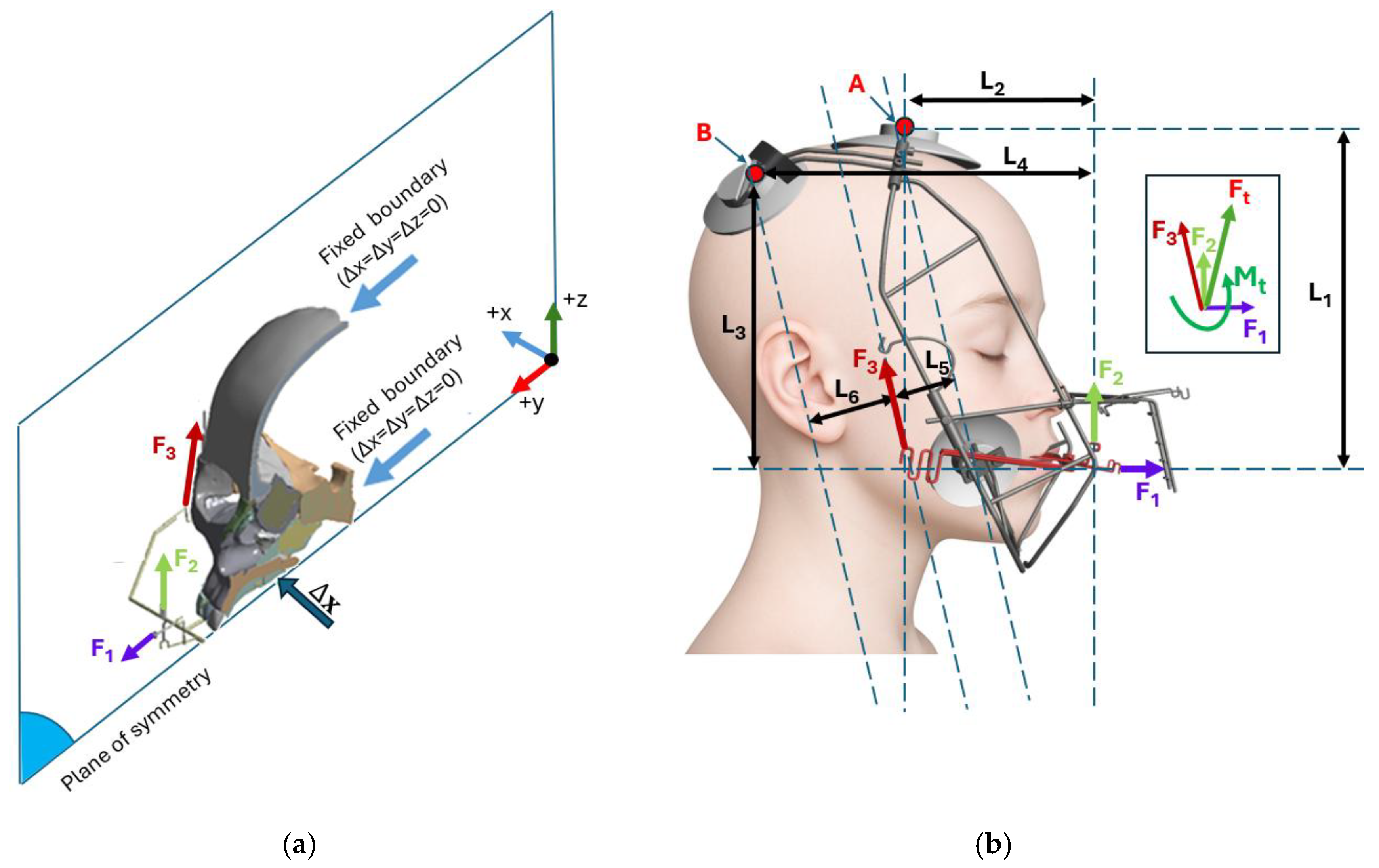
Forces are applied to the RAMPA via rubber bands. As depicted in Figure 4, six forces are typically utilized: two horizontal (anterior) forces on the front hooks, and four vertical (superior) forces—two on the front hooks and two on the side hooks. The magnitudes of these forces were determined through tensile testing and are as follows [8]:
F 1 =   2.94   N ;   F 2 =   1.44   N ;   F 3 =   4.0   N
For the purposes of our simulations, only three forces were applied due to the inherent symmetry of the model. The total force ( F t ) and moment ( M t ) acting on RAMPA can be calculated as:
F t = F 1 + F 2 + F 3
M t = M A + M B
where
M A = F 1 L 1 + F 2 L 2 + F 3 L 5
M B = F 1 L 3 + F 2 L 4 + F 3 L 6
In Equations (1) and (2), F t and M t represent the resulting loads in vector form. The total force, F t , is directed anterosuperiorly. The total moment, M t , generates a rotational moment that causes the skull to rotate in the upward direction. Additionally, due to the inherent symmetry of the model, the midplate of the palatal suture (MPS) is constrained to move only within the sagittal plane. Finally, the back of the foramen magnum and the coronal suture are assumed to be fixed.
Figure 4. (a) Boundary conditions applied to the FEA model; (b) External forces applied to the FEA model and the resulting force and moment (Forces F 1 , F 2 , and F 3   are presented with the same color in both sub-figures).
Oral 05 00074 g004

3. Results

As noted in Section 2.2, the mesh parameters were adopted from the authors’ previously validated FEA [9,10], and the final mesh is significantly finer than those used in comparable work [8,24,25]. Although a separate convergence test was not performed here, the high mesh resolution—especially near sutures—supports the reliability of the numerical results.
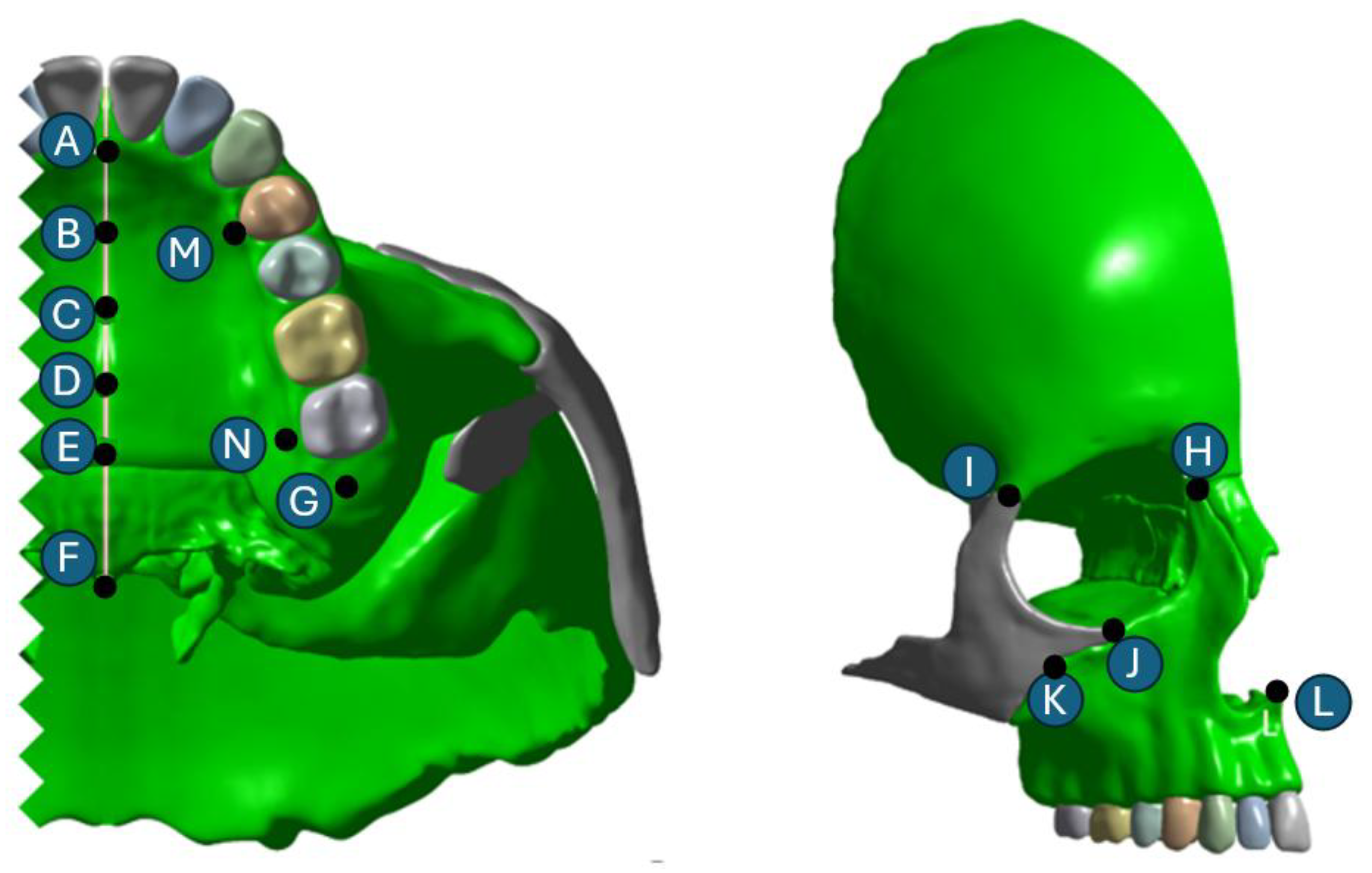
With confidence in the mesh quality established, we proceed to examine how variations in suture Young’s modulus influence skull deformation under RAMPA loading. To thoroughly evaluate how the suture Young’s modulus affects skull deformation, we present our results using color contour plots, line graphs, and tables, focusing on key landmark points (Figure 5). This approach aligns with recommendations from previous studies [8,17].
For comparative analysis, all results are normalized against the deformation of a model with a suture Young’s modulus of 50 MPa. This value was selected as the average property for suture material [6] and serves as our baseline case. This normalization allows us to compare deformation results for other Young’s moduli—specifically 30 MPa (60% of the baseline value) and 80 MPa (160% of the baseline value)—by expressing them as percentage differences relative to the baseline model.
The results of this study are presented and discussed in the following sequence:
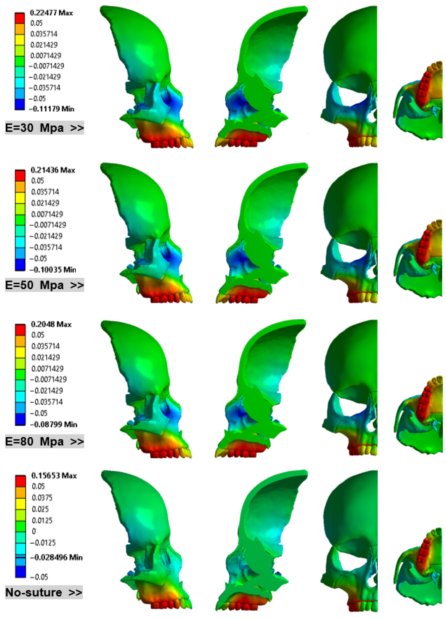
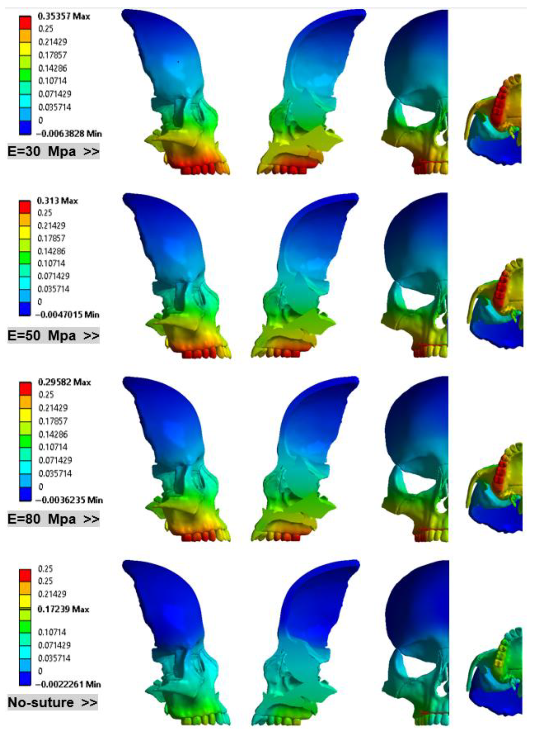
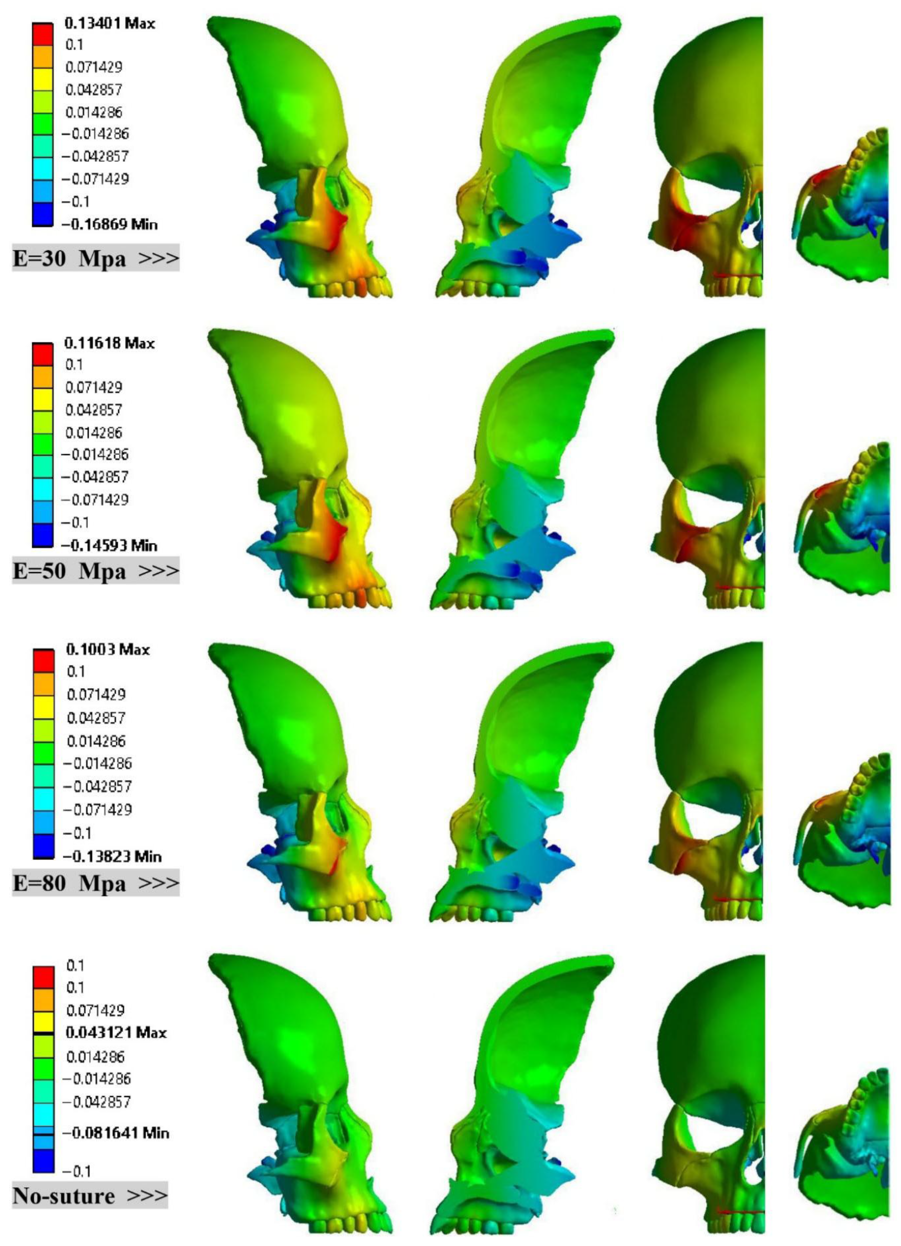
  • Displacement Contours and Stress Distributions: Figure 6, Figure 7 and Figure 8 illustrate and compare the displacement contours in the lateral direction, anterior, and vertical directions, followed by von Mises stress distributions on the skull bones in Figure 9.
  • Vertical Maxillary Movement: Figure 10a,b analyze the vertical expansion and the relative displacement of the maxilla, on points A–F (Figure 5).
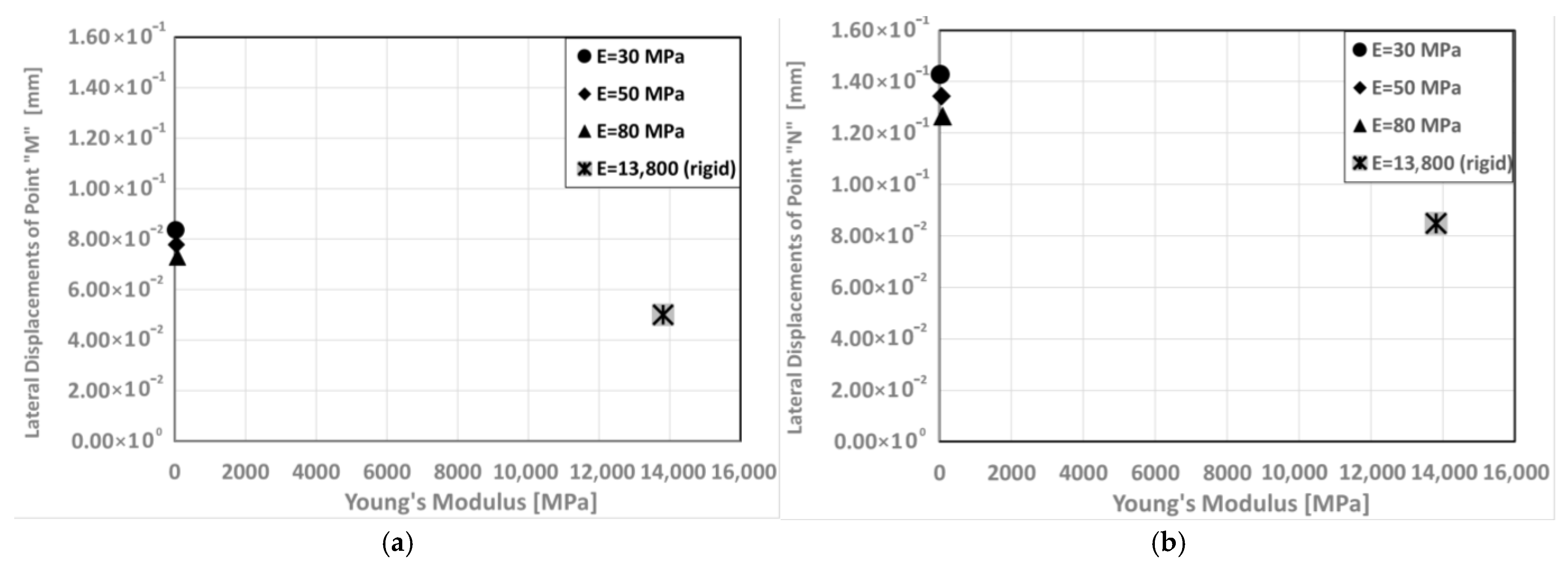
  • Lateral Expansion of Maxillary bone: Figure 11 investigates the displacements of point M and N in the lateral direction in models with different Young’s modulus.
  • Tabular Summaries of Key Data:
    • Table 2 provides a summary of how the suture Young’s modulus affects the maximum and minimum displacements.
    • Table 3 and Table 4 present the nodal displacements for 12 designated landmark points (Figure 5A–L).

4. Discussion

Regarding displacement in the lateral direction (Figure 6), increasing the Young’s modulus from 30 MPa to 80 MPa does not alter the overall displacement patterns. Areas near the nasal bone consistently exhibit the minimum displacement values, while the inner part of the maxillary bone (near points M and N) shows the largest displacement. For the 30 MPa model, the minimum displacement is approximately 10% lower than that of the 50 MPa model. Conversely, the maximum displacement increases by about 5%. This indicates that reducing the Young’s modulus from 50 MPa to 30 MPa results in a total deviation of 15% (10% + 5%) in the lower and upper bounds of predicted lateral displacements. Similarly, a comparison between the 80 MPa and 50 MPa models reveals that the minimum and maximum lateral displacements decreased by −12% and −4%, respectively, leading to a total decrease of 16%. Notably, the absolute change rate for negative displacement is comparable to that of positive displacement (16% vs. 15%).
A comparison between the results of the no-suture model and those of the E = 50 MPa model reveals significant differences in the minimum and maximum displacement values in the X (lateral) direction, despite the overall trend remaining similar. The observed trend indicates that the maxillary bone near the nasal and lacrimal bones exhibits positive movement, while the maxillary bone above the second molar tooth shows negative movement. These opposing displacements induce a rotational effect around the vertical) axis. Furthermore, the positive movement of the maxilla results in an expansion of the orbital cavity in the lateral direction.
Figure 7 illustrates distinct patterns in anterior displacement based on the Young’s modulus of the sutures. For the 30 MPa model, the maximum lateral displacement is 13% larger than that observed in the 50 MPa model. Conversely, in the 80 MPa model, the maximum displacement is 94% of the 50 MPa model’s value, indicating a 6% deviation. When comparing this 6% deviation in the anterior (Y) direction with the 15% deviation observed in the lateral (X) direction, it becomes evident that the skull exhibits greater stiffness in the anterior (Y) direction. This conclusion is further supported by comparing the maximum lateral displacement of the 50 MPa model with that of the no-suture (rigid) model, which confirms the skull’s higher rigidity in the anterior (Y) direction compared to the lateral (X) direction.
From Figure 8, one can observe clear trends in the superior (Z) displacement based on suture Young’s modulus. The maximum deformation in the superior direction for the E = 30 MPa model is approximately 15% higher than that for the E = 50 MPa model. Conversely, a comparison between the E = 80 MPa and E = 50 MPa models reveals that the maximum value decreases by about 9%. These changes collectively demonstrate a linear trend. Furthermore, the minimum and maximum deflections in the no-suture (rigid) model are 56% and 37%, respectively, of those observed in the E = 50 MPa model. Figure 8 also indicates that sutured models consistently predict maximum deflections on the zygomatic bone, while an area near the midpalatal suture exhibits the minimum values. A comprehensive summary of these displacement changes is provided in Table 2.
According to Figure 9, as the Young’s modulus increases from 30 MPa to 80 MPa, the overall von Mises stress distribution patterns remain largely similar. The locations of both minimum and maximum stress values are unchanged within this range. However, in the no-suture (rigid) model, the von Mises stress distribution differs significantly. These differences are particularly noticeable in two key areas: near the coronal suture (adjacent to the nasal bone) and inside the orbital cavity.
Figure 10a clearly illustrates that, when gHu-1 is combined with RAMPA, the downward movement of the MPS (from points A to F) is mitigated in all sutured models. These models consistently follow a similar trend, further confirming the upward movement of the maxillary bone due to RAMPA. In stark contrast, the no-suture model exhibits distinct behavior. From points A to B, the vertical displacement values remain constant. This is then followed by a significant upward movement from points B to C, which directly contrasts with the steady downward trend observed in the sutured models. Between points C and F, the rigid model shows a continuous decline, but both the slope and the final displacement values differ markedly from those observed in the sutured models. The observed upward and downward movements of these points directly correspond to the motion of the vomer bone and soft palate. These findings conclusively demonstrate that, regardless of the specific suture material properties, RAMPA effectively moves the posterior part of the maxilla upward and the entire skull forward. This makes RAMPA a highly promising tool in orthodontic treatment, especially for addressing anterosuperior movements in conditions such as long-face syndrome. To further complete this discussion, the relative movement of all models was compared against that of the model with E = 50 MPa (Figure 10b). The results clearly demonstrate that suture stiffness has a significant influence on the relative movement of the MPS, although no specific trend was observed from the results.
Finally, Figure 11a,b illustrate that the displacement of point N in lateral direction is approximately 58% greater than that of point M. Referring back to Figure 4, this significant difference indicates that, as a result of using the RAMPA, the posterior part of the maxilla expands more in the X direction than the anterior part. Furthermore, the displacement values across the suture cases consistently demonstrate a nearly linear variation in the X direction with respect to Young’s modulus. For example, the displacements of both points M and N in the 30 MPa model are approximately 7% higher than those in the 50 MPa model, while the 80 MPa model shows a 6% decrease relative to the 50 MPa case—reflecting the expected inverse relationship between stiffness and deformation, consistent with Hooke’s law under linear conditions.
An additional insight from Figure 11 is that, while the suture cases exhibit this expected linear behavior, the rigid (no-suture) model deviates significantly. This divergence reinforces the notion that omitting or oversimplifying suture properties can lead to unrealistic predictions in FEA, especially when modeling complex craniofacial structures.

5. Conclusions

Craniofacial sutures exhibit significant variability in material properties across patients of different ages, sexes, and races when subjected to orthodontic appliances. This study establishes a foundation for understanding the impact of suture properties on the performance of RAMPA by examining how the Young’s modulus of craniofacial sutures influences the anterosuperior protraction achieved through this device.
The findings demonstrate the effectiveness of RAMPA in achieving anterosuperior protraction, making it a promising treatment option for patients with long-face syndrome. Additionally, the observed linear relationship between craniofacial deformation and Young’s modulus provides a predictive basis for treatment outcomes in diverse patients undergoing RAMPA. By utilizing interpolation or extrapolation techniques, this approach enables more personalized and precise treatment planning.
Key findings include:
  • Maxillary Rotation: Regardless of the suture material properties, RAMPA consistently rotates the maxilla around the X-axis, resulting in an upward rotation.
  • Consistent Linear Displacement Slopes: Models incorporating sutures demonstrate consistent linear displacement slopes (approximately 15%) in the X, Y, and Z directions. The locations of minimum and maximum displacements remain unchanged across these sutured models. However, the rigid (no-suture) model predicts significantly different patterns and values for both minimum and maximum displacements.
  • Directional Rigidity of the Skull: The skull is mechanically more rigid in the Y direction (anterior) than in the X (lateral) direction. Furthermore, this rigidity increases as suture stiffness increases.
  • Mitigation of Downward Displacement: RAMPA significantly mitigates the downward displacements caused by the intraoral device on the midpalatal suture.
  • MPS Deformation Patterns: Sutured models treated with RAMPA exhibit a consistent downward displacement trend in the MPS from the front to the back. In sharp contrast, the no-suture (rigid) model shows a completely different deformation pattern.
While this study provides valuable findings for clinicians in understanding the impact of RAMPA based on the linear isotropic elastic modulus of sutures, the authors strongly suggest that future finite element simulations incorporate sutures with anisotropic material properties, as this would more accurately reflect their biomechanical behavior. In addition, investigating nonlinear finite element analysis and comparing the results with those from linear analysis would help clarify the influence of the modeling approach on simulation outcomes. Finally, future research could also explore assigning different material properties to bones and modeling bones themselves as anisotropic materials to further enhance the anatomical and mechanical fidelity of the simulations.

6. Disclosure

The authors whose names are listed immediately below certify that they have NO affiliations with or involvement in any organization or entity with any financial interest (such as honoraria; educational grants; participation in speakers’ bureaus; membership, employment, consultancies, stock ownership, or other equity interest; and expert testimony or patent-licensing arrangements) or non-financial interest (such as personal or professional relationships, affiliations, knowledge, or beliefs) in the subject matter or materials discussed in this manuscript.

Author Contributions

Y.M.: Data Curation, Methodology, Supervision; M.M.: CAD, FEA Software and post-processing, Writing-the draft and original manuscripts; Y.O.-K.: Data Curation, Validation; B.C.: Conceptualization, Writing-Reviewing and Editing, Supervision; P.E.: CAD, Validation. All authors have read and agreed to the published version of the manuscript.

Funding

This research received no external funding.

Data Availability Statement

Data is contained within the article.

Conflicts of Interest

Author Peiman Emamy was employed by the company Irsa Sanat Shar NoAfarin Engineering Co. The remaining authors declare that the research was conducted in the absence of any commercial or financial relationships that could be construed as a potential conflict of interest.

References

  1. Romanyk, D.L.; Collins, C.R.; Lagravere, M.O.; Toogood, R.W.; Major, P.W.; Carey, J.P. Role of the midpalatal suture in FEA simulations of maxillary expansion treatment for adolescents: A review. Int. Orthod. 2013, 11, 119–138. [Google Scholar] [CrossRef]
  2. Moazen, M.; Curtis, N.; O’Higgins, P.; Jones, M.E.H.; Evans, S.E.; Fagan, M.J. Assessment of the role of sutures in a lizard skull: A computer modelling study. Proc. R. Soc. B 2008, 276, 39–46. [Google Scholar] [CrossRef]
  3. Jasinoski, S.C.; Reddy, B.D. Mechanics of cranial sutures during simulated cyclic loading. J. Biomech. 2012, 45, 2050–2054. [Google Scholar] [CrossRef]
  4. Popowics, T.E.; Herring, S.W. Load transmission in the nasofrontal suture of the pig, Sus scrofa. J. Biomech. 2007, 40, 837–844. [Google Scholar] [CrossRef]
  5. Eom, J.; Bayome, M.; Park, J.H.; Lim, H.J.; Kook, Y.A.; Han, S.H. Displacement and stress distribution of the maxillofacial complex during maxillary protraction using palatal plates: A three-dimensional finite element analysis. Korean J. Orthod. 2018, 48, 304–315. [Google Scholar] [CrossRef]
  6. Jasinoski, S.C.; Reddy, B.D.; Louw, K.K.; Chinsamy, A. Mechanics of cranial sutures using the finite element method. J. Biomech. 2010, 43, 3104–3111. [Google Scholar] [CrossRef] [PubMed]
  7. Mitani, Y.; Banabilh, S.M.; Singh, G.D. Craniofacial changes in patients with Class III malocclusion treated with the RAMPA system. Int. J. Orthod. Milwaukee 2010, 21, 19–25. [Google Scholar] [PubMed]
  8. Mitani, Y.; Choi, B.; Choi, J. Anterosuperior protraction of maxillae using the extraoral device, RAMPA; finite element method. Comput. Methods Biomech. Biomed. Eng. 2018, 21, 722–729. [Google Scholar] [CrossRef]
  9. Moshfeghi, M.; Mitani, Y.; Choi, B.; Emamy, P. Finite element simulations of the effects of an extraoral device, RAMPA, on anterosuperior protraction of maxillae and comparison with gHu-1 intraoral device. ANGEL Orthod. 2021, 91, 804–814. [Google Scholar] [CrossRef] [PubMed]
  10. Mitani, Y.; Moshfeghi, M.; Kumamoto, N.; Choi, B. Finite element and clinical analyses of effects of a new intraoral device (VomPress) combined with extraoral RAMPA on improving the overjet of craniofacial complex. Comput. Methods Biomech. Biomed. Eng. 2021, 25, 1099–1110. [Google Scholar] [CrossRef]
  11. Choi, J.W.; Kim, N. Clinical application of three-dimensional printing technology in craniofacial plastic surgery. Arch. Plast. Surg. 2015, 42, 267–277. [Google Scholar] [CrossRef] [PubMed]
  12. Van Hevele, J.; Nout, E.; Claeys, T.; Meyns, J.; Scheerlinck, J.; Politis, C. Bone-anchored maxillary protraction to correct a class III skeletal relationship: A multicenter retrospective analysis of 218 patients. J. Cranio-Maxillofac. Surg. 2018, 46, 1800–1806. [Google Scholar] [CrossRef]
  13. Andreucci, C.A.; Fonseca, E.M.M.; Jorge, R.N. Biomechanics of a Novel 3D Mandibular Osteotomy Design. Designs 2024, 8, 57. [Google Scholar] [CrossRef]
  14. Savoldi, F.; Tsoi, J.; Paganelli, C.; Matinlinna, J.P. Biomechanical behaviour of craniofacial sutures during distraction: An evaluation all over the entire craniofacial skeleton. Dent. Mater. 2017, 33, e290–e300. [Google Scholar] [CrossRef] [PubMed]
  15. Li, Y.; Ortiz, C.; Boyce, M.C. Stiffness and strength of suture joints in nature. Phys. Rev. E 2011, 84, 062904. [Google Scholar] [CrossRef]
  16. Rees, J.S.; Jacobsen, P.H. Elastic modulus of the periodontal ligament. Biomaterials 1997, 18, 995–999. [Google Scholar] [CrossRef]
  17. Lee, S.C.; Park, J.H.; Bayome, M.; Kim, K.B.; Araujo, E.A.; Kook, Y.A. Effect of bone-borne rapid maxillary expanders with and without surgical assistance on the craniofacial structures using finite element analysis. Am. J. Orthod. Dentofac. Orthop. 2014, 145, 638–648. [Google Scholar] [CrossRef]
  18. Lillie, E.M.; Urban, J.E.; Weaver, A.A.; Powers, A.K.; Stitzel, J.D. Estimation of skull table thickness with clinical CT and validation with microCT. J. Anat. 2015, 226, 73–80. [Google Scholar] [CrossRef]
  19. Lillie, E.M.; Urban, J.E.; Lynch, S.K.; Weaver, A.A.; Stitzel, J.D. Evaluation of Skull Cortical Thickness Changes with Age and Sex from Computed Tomography Scans. J. Bone Miner. Res. 2016, 31, 299–307. [Google Scholar] [CrossRef]
  20. Qian, H.; Chen, J.; Katona, T.R. The influence of PDL principal fibers in a 3-dimensional analysis of orthodontic tooth movement. Am. J. Orthod. Dentofac. Orthop. 2001, 120, 272–279. [Google Scholar] [CrossRef]
  21. Cattaneo, P.M.; Dalstra, M.; Melsen, B. The finite element method: A tool to study orthodontic tooth movement. J. Dent. Res. 2005, 84, 428–433. [Google Scholar] [CrossRef]
  22. Fricke-Zech, S.; Gruber, R.M.; Dullin, C.; Zapf, A.; Kramer, F.J.; Kubein-Meesenburg, D.; Hahn, W. Measurement of the midpalatal suture width. Angle Orthod. 2012, 82, 145–150. [Google Scholar] [CrossRef] [PubMed]
  23. Fill, T.S.; Toogood, R.W.; Major, P.W.; Carey, J.P. Analytically determined mechanical properties of, and models for the periodontal ligament: Critical review of literature. J. Biomech. 2012, 45, 9–16. [Google Scholar] [CrossRef] [PubMed]
  24. Serpe, L.C.T.; Las Casas, E.B.; Toyofuku, A.C.M.M.; González-Torres, L.A. A bilinear elastic constitutive model applied for midpalatal suture behavior during rapid maxillary expansion. Res. Biomed. Eng. 2015, 31, 319–327. [Google Scholar] [CrossRef]
  25. Lee, H.; Ting, K.; Nelson, M.; Sun, N.; Sung, S.J. Maxillary expansion in customized finite element method models. Am. J. Orthod. Dentofac. Orthop. 2009, 136, 367–374. [Google Scholar] [CrossRef]
Figure 1. Different parts simulated in the FEA; (a) frontal view of skull; (b) cancellous bone of skull; (c) teeth; and (d) periodontal ligament.
Oral 05 00074 g001
Figure 2. (a) Mesh sensitivity analysis performed on the sutures; (b) Two views of the final tetrahedral mesh arrangement used for the FEA models in the present research.
Oral 05 00074 g002
Figure 3. (a) RAMPA worn by a manikin; (b,c) side and top views of gHu-1 connected to the metal rods.
Oral 05 00074 g003
Figure 5. Landmark points for analyzing displacements and stresses; (A): near the incisive foramen; (E): near the palatine bone; (BD): equidistance points on AE line; (F): posterior nasal spine; (G): maxillary tuberosity; (H): frontomaxillary suture; (I): frontozygomatic suture; (J): infraorbital margin; (K): zygomaticomaxillary suture; (L): anterior nasal spine; (M): on the maxillary near the first premolar; (N): on the maxillary near the second molar.
Oral 05 00074 g005
Figure 6. Distribution of displacement along the X-axis (lateral direction) for different values of Young’s modulus.
Oral 05 00074 g006
Figure 7. Distribution of displacement along the Y-axis (anterior direction) for different values of Young’s modulus.
Oral 05 00074 g007
Figure 8. Distribution of displacement along the Z-axis (superior direction) for different values of Young’s modulus.
Oral 05 00074 g008
Figure 9. Distribution of von-Mises stress for cases with different Young’s modulus.
Oral 05 00074 g009
Figure 10. Impact of different Young’s modulus on (a) Displacement of midpalatal points for models in vertical direction; (b) The relative vertical displacements with respect to case with E = 50 MPa.
Oral 05 00074 g010
Figure 11. Effect of Young’s modulus on lateral displacements of point M (a); and point N (b).
Oral 05 00074 g011
Table 1. Material properties applied to the FEA [9,10,17].
ItemYoung’s Modulus [MPa]Poisson’s Ratio
Cortical bone13,800 MPa0.26
Cancellous bone1370 MPa0.3
Stainless steel (AISI 316)193,000 MPa0.31
Teeth18,600 MPa0.31
Periodontal ligament50 MPa0.49
Midpalatal suture (MPS)50 MPa50
Acrylic Resin
(Orthocryl® from DENTAURUM, Ispringen, Germany)
3543 MPa0.3
Sutures30 MPa (Case 1)-
50 MPa (Case 2)0.49
80 MPa (Case 3)0.49
13,800 MPa (rigid; Case 4)0.49
Table 2. The ratio of Maxi. and Min. displacements of the No-suture model to the models with flexible sutures.
X DirectionY DirectionZ Direction
Variation in maximum ratio69.6%~76.1%34.9%~61.1%32.1–43.1%
Variation in minimum ratio25.1%~31.8%48.7%~58.1%49.0–59%
Table 3. Midpalatal suture displacement for cases with suture of different Young’s Modulus.
PointCase 1 (30 MPa)Case 2 (50 MPa)Case 3 (80 MPa)Case 4 (No-Suture)
X [mm]Y [mm]Z [mm]X [mm]Y [mm]Z [mm]X [mm]Y [mm]Z [mm]X [mm]Y [mm]Z [mm]
A3.155 × 10 −20.195−5.228 × 10 −32.590 × 10 −20.163−1.470 × 10 −22.141 × 10 −20.152−1.670 × 10 −21.96 × 10 −37.2728 × 10 −2−1.785 × 10 −2
B2.215 × 10 −20.195−1.189 × 10 −21.853 × 10 −20.168−1.704 × 10 −21.521 × 10 −20.159−1.761 × 10 −21.233 × 10 −38.496 × 10 −2−1.786 × 10 −2
C2.714 × 10 −20.207−3.244 × 10 −22.283 × 10 −20.181−2.945 × 10 −21.95 × 10 −20.172−2.564 × 10 −22.655 × 10 −39.727 × 10 −2−2.516 × 10 −3
D3.546 × 10 −20.225−8.773 × 10 −22.868 × 10 −20.197−7.551 × 10 −22.355 × 10 −20.187−6.640 × 10 −21.936 × 10 −30.109−1.723 × 10 −2
E4.107 × 10 −20.228−0.1313.342 × 10 −20.200−0.1142.759 × 10 −20.190−0.1021.624 × 10 −30.112−3.348 × 10 −2
F−8.089 × 10 −20.238−0.126−1.432 × 10 −40.209−0.113−1.822 × 10 −40.200−0.1065.904e−60.122−6.072 × 10 −2
Table 4. Maxillofacial landmarks displacement for cases with suture of different Young’s Modulus.
PointCase 1 (30 MPa)Case 2 (50 MPa)Case 3 (80 MPa)Case 4 (No-Suture)
X [mm]Y [mm]Z [mm]X [mm]Y [mm]Z [mm]X [mm]Y [mm]Z [mm]X [mm]Y [mm]Z [mm]
G0.1540.308−0.0590.1440.271−0.050.1340.256−0.0550.0760.143−0.034
H0.0020.0760.0260.0020.0650.0180.0020.0600.0120.0010.0350.000
I0.0000.0450.0300.0010.0340.0230.0010.0280.0190.0050.0140.012
J−0.0410.1210.109−0.0360.1070.093−0.0290.1040.079−0.0040.0670.027
K−0.0270.1690.115−0.0250.1500.101−0.0200.1430.0890.0020.0770.036
L−0.0050.1730.019−0.0030.1530.009−0.0020.1470.0050.0000.092−0.012
Disclaimer/Publisher’s Note: The statements, opinions and data contained in all publications are solely those of the individual author(s) and contributor(s) and not of MDPI and/or the editor(s). MDPI and/or the editor(s) disclaim responsibility for any injury to people or property resulting from any ideas, methods, instructions or products referred to in the content.