Simple Summary
Microbeam radiation therapy uses microscopic beams spaced hundreds of micrometers apart for cancer treatment. The unique treatment field contains two distinct regions of the radiation dose: the peak (in-beam) and valley (between beams). This work compares which dose region is the most important for tumor control and investigates dose modulation with Monte Carlo simulations in Geant4, and is assessed by long-term survival of rats bearing 9 L-gliosarcoma tumors. A bolus modulated the peak and valley doses with depth under the same irradiation conditions to understand which dose was most crucial for tumor control, to improve tumor dose targeting and to reduce variation in the survival outcome.
Abstract
Synchrotron Microbeam Radiation Therapy (MRT) is an innovative technique that spatially segments the synchrotron radiation field for cancer treatment. A microbeam peak dose is often hundreds of times the dose in the valley (the sub-millimeter region between the peaks of the microbeams). Peak and valley doses vary with increasing depth in tissue which effects tumor dose coverage. It remains to be seen whether the peak or valley is the primary factor in MRT cancer control. This study investigates how unilateral MRT doses can be modulated using a bolus, and identifies the valley dose as a primary factor in MRT cancer control. Fischer rats bearing 9 L gliosarcoma tumors were irradiated with MRT at the Imaging and Medical Beam Line of the Australian Synchrotron. MRT valley doses of 8–15 Gy (250–1040 Gy peak doses) were used to treat tumors with and without a 5 mm dose-modulating bolus. Long-term survival depended on the valley dose primarily (92% correlation), and the use of the bolus reduced the variance in animal survival and improved to the mean survival of rats treated with MRT by 47% and 18% using 15 Gy and 8 Gy valley doses, respectively.
1. Introduction
Glioblastoma multiforme (GBM) is the most common and aggressive of all primary brain tumors [1]. GBMs are often difficult to surgically remove and have inherent resistances to both radiation and chemotherapy [2,3]. Median survival is 3 months without treatment, and only 18 months with surgery and adjuvant radiotherapy (RT) and chemotherapy [4].
Conventional radiotherapy is the primary contributor to patient survival after surgery and is typically delivered up to a maximal dose of 60 Gy [1]. However, radiosurgical and hypo-fractioned stereotactic radiosurgery (SRS) show improved survival outcomes for GBM patients [5], including SRS boosts to the standard RT course [6].
Novel RT techniques such as synchrotron radiation therapy show promising outcomes for cancer treatment and have potential as a treatment boost for standard RT [7]. Synchrotrons generate X-rays with dose rates of tens to thousands of Gy per second, which has useful therapeutic implications, including overcoming radiation resistance for GBMs [8,9,10,11] and promoting normal tissue sparing through FLASH therapy effects [9,12].
The highly intense, polarized synchrotron light is collimated into micron-sized beamlets to produce a spatially fractionated field [9,10,11,13,14,15,16,17,18,19,20]. This technique, Microbeam Radiation Therapy (MRT), has been considered for GBM treatment as it combines the advantages of synchrotron radiation with microscopic radiosurgery. MRT typically uses high-dose microbeams in the order of hundreds of Gy in a single fraction. This is remarkably well-tolerated by normal tissue as the in-beam dose is limited to 25–75-micron-wide tracks that are spaced 200–400 microns apart for tissue sparing [17]. Further, MRT has been shown to impair tumor vasculature support, enhance immune responses to cancer cells, and facilitate tumor regression in preclinical studies [10,11,17,18,19,20]. Single, multiple, and grid MRT fields have been explored with promising outcomes in rodents, duck embryos, piglets, and canines [14,21].
Quality assurance for MRT is performed in water-equivalent phantoms using high-resolution detectors or Gafchromic film [15,22,23,24]. Simulations are used to model the MRT dose within certain target volumes [24,25,26]. Due to the spatially segmented MRT fields, two distinct dose regions occur. These correspond to the in-beam dose (peaks) and dose between microbeams (valleys). With increasing depth in a target volume, the absorbed dose in each region behaves very differently [24]; peak doses decline steadily with depth and valley doses increase and plateau at greater depths before declining. This has consequences for the accurate prescription of target dose coverage in MRT. The challenge of individualized tumor volume coverage, in practice, however, has only recently been addressed. Our previous study indicated that adequate valley dose coverage of the tumor for individual animals has a significant impact on long-term survival [11].
MRT for GBMs has been extensively investigated using 9 L gliosarcoma (9LGS) cells in rats [10,11,18,19]. Studies have documented the 9LGS cancer response to MRT in terms of proliferation, immune activity, long-term quality of life, histology, and long-term survival. MRT increases 9LGS vasculature deterioration, enhances the immune response [20], and increases rodent survival when compared to seamless broad beam [19].
MRT is also exceptionally well tolerated compared to the conventional seamless broad beam and has also been shown to preserve the normal function of the brain long term. Studies measuring memory loss [27,28] and behavioral changes such as anxiety and depression in rats [29] demonstrate minimal impact and recoverable long-term normal brain function. However, in all this there has been no definitive assessment on whether the peak or valley dose is the primary factor in MRT.
The goal of this work is to investigate how MRT dose coverage can be modulated to meet treatment requirements, ensure better tumor dose coverage, and provide further evidence for the valley dose as the primary factor in both survival and normal tissue tolerance. Dose modulation in radiotherapy is achieved with a bolus material. Bolus use in brain radiotherapy with megavoltage or electron beams is often implemented to reduce hotspots and improve the dose coverage of superficial tumors [30,31]. For the first time, we will use a dose-modulating bolus for MRT tumor dose conformity and investigate the effect of a bolus on critical structures. We will characterize the MRT field with simulation verified by dosimetry and assess the long-term survival of GBM-bearing rats.
2. Methods
2.1. Cell Preparation
9LGS cells were acquired from the European Collection of Cell Cultures (ECACC). 9LGS cells were cultured in T75 cm2 flasks containing Gibco® Dulbecco’s Modified Eagle Medium supplemented with 10% fetal bovine serum (FBS) and 1% penicillin and streptomycin (PS). Cells were incubated at 37 °C and 5% (v/v) CO2. At passage 12–14, 9LGS cells were implanted into the animals.
2.2. Tumor Implantation and Animal Monitoring
All operative procedures and animal care conformed to the guidelines of the Australian Code for the Care and Use of Animals for Scientific Purposes [32] under the approval of the University of Wollongong and Australian Synchrotron animal ethics committees’ agreements (AE17/05 and AS-2017-01, respectively).
Over the course of 3 experiments, 35 Fisher rats (7-week-old, inbred, male F344/Arc) were acquired from the Animal Resource Centre, Canning Vale, Perth, Australia. All animals were housed at the Australian Synchrotron, Clayton, Victoria, Australia for tumor implantation and MRT. A total of 2–3 animals were housed in ventilated cages containing Pura Chips bedding, specialty irradiated feed, with access to water and environmental enrichments. Rats experienced 1 week of acclimation before tumor implantation surgery at 8 weeks of age.
The procedure for implantation has been described by Engels et al. [11]. Two hours prior to surgery, pre-emptive analgesia was provided by voluntary oral administration of 0.4 mg/kg buprenorphine in Nutella paste (Ferrero Australia Pty Ltd., Lithgow, NSW, Australia). Rats were anesthetized for surgery with 2.5 to 3% isoflurane after induction with 5% isoflurane. Ophthalmic lubricant was applied to protect the eyes and each rat was placed on a heat mat and monitored using PhysioSuite®, (Kent Scientific Corporation, Torrington, CT, USA). The scalp was shaved, and bupivacaine (4 mg/kg at 0.25%) was injected subcutaneously in the scalp for local analgesia. Rats were mounted with ear bars on a small animal Kopf Model 900 stereotaxic frame, which includes a microinjection unit (Kopf Instruments, Tujunga, CA, USA). Once positioned, a solution of chlorhexidine in alcohol was applied to the scalp to clean the area, followed by 10% povidone–iodine antiseptic, and a disposable sterile plastic sheet covered the rat.
An aseptic environment was implemented for surgery [33,34]. Surgical drapes, instruments, and protective gear were sterile, and surgical equipment was repeatedly sterilized for each rat [34]. A dorsal midline incision was made through the plastic sheet commencing posterior to the eyes and extending rostral to the ears. The skull was exposed, and any minor bleeds cauterized. A 0.6–1 mm burr hole was made at 3.5 mm to the right of the bregma crossing on the skull.
9LGS cells were harvested from T75 cm2 flasks by washing with Dulbecco’s Phosphate Buffered Saline (DPBS) and trypsinizing for 5 min. Cells were counted, centrifuged and washed with DMEM only (without FBS or PS) twice. After final resuspension in DMEM, the 9LGS concentration was 10,000 cells per μL for injection. 9LGS cells were drawn into a 2 µL Neuros Hamilton syringe with a 30-gauge needle (Hamilton Company, Reno, NV, USA) and were loaded onto the microinjection unit. The syringe needle was inserted through the burr hole to a 6 mm depth into the right caudate nucleus, over 2 min. Before injection, the syringe was retracted 0.5 mm to produce a void for the cells. 1 µL of cells was injected with the microinjection unit over 3 min. Before withdrawing, a 1 min pause was allowed, and then the needle was retracted slowly and continuously over 2 min to avoid the deposition of cells along the path of needle entry. The burr hole was disinfected with 70% ethanol and the wound closed with polypropylene non-absorbable monofilament sutures.
2.3. Tumor Imaging
All rats were prepared for CT imaging on day 11 after tumor implantation and imaged at the Monash Biomedical Imaging (MBI) Facility, Clayton, VIC, Australia. Initially, a Siemens Inveon PET/CT Scanner (97 µm acquisition resolution and 80 kVp energy) was used for 10 rats. As the duration of the micro-CT was too lengthy for optimum contrast accumulation in the tumor, the remaining 25 rats were imaged using a Somatom go.Up (slice thickness of 0.6 mm and 80–110 kVp) in accordance with the clinical imaging protocol outlined in our earlier work [35].
Prior to imaging, rats were pre-warmed under a heat lamp before anesthesia induction using 5% isoflurane. The rats were maintained at 2.5–3% isoflurane for CT imaging, and warmed with a heat mat. Vital signs were monitored and maintained.
An intravenous injection of Iomeron-350 (Regional Health Care Group, Rosebery, NSW & Bracco Ltd., LIN, Italy) was used to visualize the tumor in the brain. The injected iodinated contrast media had a concentration of 350 mg/mL iodine. Before contrast injection, the tail was warmed to dilate the veins. The tail was swabbed with water and then disinfected with 70% (v/v) ethanol before a 24 G ¾” Teflon catheter was inserted into the lateral tail vein. A volume of 1 mL of contrast was gradually injected. For the case of the micro-CT, a pump was used for imaging during the 8 min CT acquisition. Rats were positioned on small couch bed with ear bars to keep the skull level in the field. After imaging, rats were recovered from anesthesia with oxygen and placed in a warm recovery cage before returning to their home cage. After image reconstruction, the position of the tumor was measured individually in a coronal view with respect to the bony anatomy of the rat.
2.4. MRT Irradiation Setup and Dosimetric Verifcation
All animal irradiations used the dynamic mode option at hutch 2B of the Imaging and Medical Beamline (IMBL) at the Australian Synchrotron. Synchrotron X-ray beams were generated using a 3T or 4T superconducting multipole wiggler to obtain a lower and higher treatment dose rate, respectively. Filtration of the synchrotron beam was 1 mm Cu with 2.4 mm Al (CuAl) and 2 × 2.4 mm Al (AlAl), for 3T and 4T, respectively. These filtrations produced a weighted mean beam energy of 81 keV and 58 keV, respectively [16]. In-beam dose rates for 3T and 4T at 12.5 mm reference depth using an 8 mm × 8 mm field were 280 Gy/s and 3700 Gy/s, respectively. A tungsten carbide multi-slit collimator (MSC) striated the broad synchrotron beam into microbeams (50 µm in width and 400 µm pitch). A conformal tungsten mask produced a treatment field size of 8 mm × 8 mm to adequately cover the projected tumor target volume in a single fraction of unidirectional MRT. Tumor dose coverage was achieved by moving the target (and mask) vertically at a rate of ~0.5 mm/s. As such, the 0.5 mm high intrinsic MRT field travels from the cranial to caudal direction on each rat, targeting the tumor from the top of the skull, as shown in Figure 1.
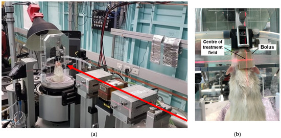
Figure 1.
MRT irradiation beam set up (a) showing beam direction (red arrow) and treatment stage position. On treatment stage (beam view) placement of bolus is shown (b) with target position shown with red laser light.
Dosimetric verification was performed with the X-Tream System developed by the Centre for Medical Radiation Physics (CMRP) [36,37]. Solid-state epitaxial (EPI) detectors were used to measure the peak and valley doses in the MRT field due to their tolerance of high dose rates, high spatial resolution, and fast online readout [37]. The EPI detectors, however, first require cross-calibration with an ionization chamber (IC), as described previously [11,23]. A PTW PinPoint IC (Model 31014) was placed in a 100 × 100 × 100 mm3 RMI 457 Solid Water® phantom at 20 mm depth to measure the dose and dose rate of the broad 20 × 20 mm2 synchrotron beam. All air gaps were filled with water or pieces of Solid Water®. The IC was then replaced with the EPI detector for cross-calibration at 20 mm depth.
Following these measurements, final dosimetry was performed in a 25 × 25 × 50 mm3 Solid Water® phantom that modeled the rat head dimensions. The EPI and IC detectors were placed at 12.5 mm depth in the phantom for further cross-calibration. The MRT field dose profile of the 8 × 8 mm2 treatment field was then characterized solely with the EPI detector. Peak and valley doses were measured across 5 central microbeams, and 5 valley regions, at a 5 and 20 μm sampling step size, respectively.
Our recent study has linked Geant4 radiation transport simulations to absorbed dose measurements at various depths in Solid Water® [24]. As in our previous research, MRT dose simulations were calibrated using dose measurements in the Solid Water® rat head phantom [11]. The G4-IMBL simulation was used to record a 3D matrix of the dose deposited within the phantom. Custom Python3 analysis scripts were then used to retrieve the peak and valley dose at every depth within the phantom. The Geant4 simulations [38] and dose measurements were used to deduce the vertical target translation speed necessary to deliver the prescribed treatment dose to the target depth (tumor site) for each rat. For irradiation programs without a bolus, the target site for the prescribed dose was the same as the tumor implantation depth at 5.5 mm in the brain. Simulations were performed with and without a 5 mm water bolus to mimic the water-equivalent bolus used experimentally, made from a Super-Flex Akton® Viscoelastic Polymer (Radiation Product Design Inc., Albertville, MN, USA, which was 5 mm thick and cut to an area of 1.5 × 1.5 cm2 (see Figure 1b).
Dose–volume histograms (DVHs) were calculated for each individual tumor using the Geant4 simulations dose map along with tumor location and volume data acquired from CT imaging. The DVHs were retrospectively assessed for our first experiments (treatment programs 2, 4 and 5 in Table 1). For our final improved experiments (programs 3 and 6 in Table 1), DVHs were estimated prior to MRT to establish optimal tumor coverage conditions, and included the bolus.

Table 1.
MRT treatment programs. Bolus (yes (Y) or no (N)), valley doses, dose rates, and PVDR values are given at target depth for each treatment configuration.
2.5. MRT Animal Irradiation
On day 12, a total of 25 rats were treated with MRT in hutch 2B on IMBL. A total of 10 rats were used as controls. MRT programs were performed as described in Table 1. 3T MRT was performed in programs 2, 4, 5 and 6, and 4T MRT with program 3. A bolus was used to ensure better tumor coverage for programs 3 and 6. Each treatment program consisted of 5 rats, except the control which consisted of 10 from 2 separate experiments.
After induction with 5% isoflurane, rats were maintained under general anesthesia at 2.5–3% isoflurane while warmed with heat mats and a heat lamp. Vital signs including respiratory rate and temperature were monitored as previously. Rats were mounted on the Kopf stereotaxic frame without the microinjection unit using a bite block and ear bars. The frame was mounted on the treatment stage, securing the rat vertically, with the beam directed through the top of the skull. A heat lamp was used for warming during the treatment. See Figure 1 for animal setup.
For each rat, tumors were aligned in the MRT field using an image guidance method (SyncMRT) developed for pre-clinical radiotherapy applications on IMBL [39]. The IMBL image guidance procedure is described in the work of Engels et al. [11] and Paino et al. [35]. Briefly, 2 planar X-rays of each rat were taken prior to MRT using an X-ray tube and detected on a Hamamatsu flat panel detector. These images were co-registered with the bony landmarks obtained with the CT image. Bony landmarks included the length and width of the eye orbits, length and width of the skull, and width of the nasal bone. After the tumor position was verified within ±0.34 mm using the bony landmarks, the stage holding the Kopf stereotaxic frame was rotated and translated in 4 degrees of freedom accordingly for each rat to ensure tumor coverage using the 8 × 8 mm2 field. Two pieces of Gafchromic® film were placed anterior and posterior to the skull to confirm treatment delivery. Once image alignment was performed, the rat was treated with unidirectional MRT. The animal positioning for treatment and placement of the 5 mm bolus is shown in Figure 1.
Following MRT, the animals were recovered. During recovery, groups 1 (n = 5/10), 3, and 6 received 1 dose of 30 mg/kg of methylprednisolone and 50 mg/kg of levetiracetam to improve their short-term recovery. Groups 2 and 4 received levetiracetam and meloxicam (2 mg/kg), and animals in groups 1 (n = 5/10) and 5 had meloxicam only.
Symptom management was introduced to better manage short-term edema 4–8 h after MRT, and there was no significant impact on long-term cancer growth or survival between meloxicam or levetiracetam plus methylprednisolone in control animals (p = 0.4). All animals were monitored up to 365 days, with twice-daily checks for at least 3 weeks after MRT and until 2 weeks had passed without any clinical signs including weight loss, poor body condition, and neurological signs. From this point, daily checks were made, and monitoring increased again if animals began scoring for these clinical signs. Euthanasia was performed with pentobarbitone sodium if there was indication of a reoccurring tumor, and these primarily included neurological signs, loss of mobility, poor gait, and weight loss greater than 10%.
3. Results and Discussion
3.1. MRT Dose Modulation
The doses of the peak (in-beam) and valley regions between microbeams in the MRT field differ greatly with changing depth. Figure 2 shows the peak and valley doses with increasing depth in a rat-head phantom, simulated in Geant4 using the G4-imbl code detailed in the study Dipuglia et al. [24] and verified with dose measurements at reference conditions. With increasing depth, the peak dose declines linearly, showing minimal build-up region as is characteristic to the depth dose curves of broad kilovoltage radiation. The valley dose, however, increases with increasing depth, as noted previously [11,24].
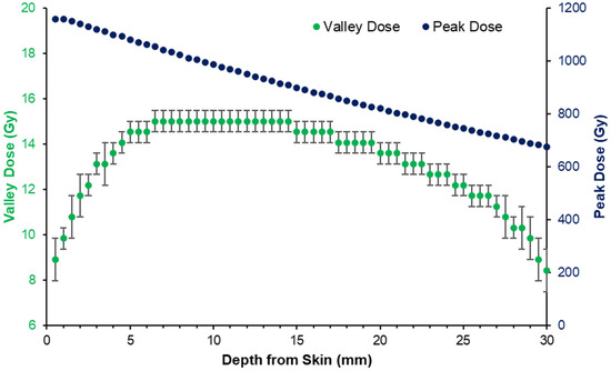
Figure 2.
Peak and valley dose with depth produced by the 3T (CuAl) treatment program 5 in Table 1, as simulated in Geant4. Dose curves calibrated to 15 Gy prescribed to the depth of tumor implantation at 5.5 mm.
As the MRT peak and valley doses varied, the tumor dose coverage was also subject to variation depending on the position of the tumor with depth in the rat brain (which spanned approximately 13 mm). According to the CT images, the majority of 9LGS tumors occupied depths of 2–8 mm from the skin layer atop the rat head, or 0–6 mm from the top of the skull. According to Figure 2, tumors at 2 mm depth may receive just 80% of the prescribed valley dose.
To modulate the MRT peak and valley doses, a bolus was used to increase the depth of the tumors for treatment groups 3 and 6 in Table 1. Figure 3 shows how the addition of a 5 mm bolus increases the effective depth of the average tumor volumes (as determined from CT imaging) from 2–3 mm to 7–8 mm, for these treatment groups. This corresponds to a reduction in the valley dose variation over the tumors from over 20% to less than 5% (according to the simulation predictions), as shown in Figure 2.
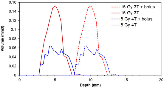
Figure 3.
Normalized distribution of 9LGS tumor volumes with respect to depth from the top of the head/bolus within each treatment group prescribed with valley doses of 8 Gy and 15 Gy (or treatment groups 3 and 6 in Table 1, respectively). Each treatment group contained 5 animals.
Figure 4 shows the DVH produced using the tumor-depth distributions from Figure 3 and the depth dose curve shown in Figure 2 for treatment group 6 in Table 1. The bolus increased the minimum valley dose (or the dose that 100% of the tumor volume receives) by 112% on average. However, the peak dose received by a portion of the tumor was reduced by over 100 Gy (8%).
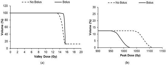
Figure 4.
Dose volume histograms of treatment group 6 in Table 1 showing the average tumor volume within the group receiving valley (a) and peak MRT doses (b).
3.2. Implementation of MRT Dose Modulation and Effect on Survival
Figure 5 shows DVHs that were developed using the peak- and valley-dose depth dependence (shown in Figure 2 and Supplementary Figure S1) for each irradiation condition, and the average tumor volume of each group. For programs 3 and 6, preliminary DVHs were developed prior to treatment to determine the best coverage dose; for programs 2, 4 and 5, DVHs were produced retrospectively.
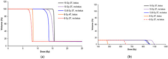
Figure 5.
Dose volume histograms (DVHs) for each MRT condition in Table 1, showing the valley dose (a) and peak dose (b) coverage of the average of the tumors from each cohort. The treatment conditions are indicated by the wiggler field and presence of the bolus.
The peak dose varied greatly across the cohorts (from 270 to 1100 Gy) due to the necessity to increase the valley dose, presence of a bolus, or variation in the beam quality (3T/4T), as shown in Figure 5b. The valley-dose coverage of the tumor was improved with the use of a bolus for the 15 Gy 3T and 8 Gy 4T treatment conditions. Without the bolus, the valley dose did not build up to a dose plateau for all cohorts, as demonstrated in Figure 2, and is represented in the curved (non-sharp) shoulders of the DVHs in Figure 5a. The use of the 5 mm bolus ensured that the target dose was delivered to 95% of the tumor prior to treatment, and )we prescribed the dose for the animal experiments according to the minimum dose the tumor would receive (or the valley dose), rather than the peak dose, based on our previous study (Engels et al. [11]).
The survival for each treatment program in Table 1 is shown in Figure 6. Dose escalation from the MRT valley dose of 8 Gy to 15 Gy increased the overall survival and, therefore, tumor control, as expected. Using the 5 mm bolus produced an overall greater consistency in the survival, likely due to less variation in the dose over the tumor target volume. Table 2 shows the survival statistics obtained from the Kaplan–Meier curves shown in Figure 6, including the mean survival time (MST) and median survival time (MeST) after tumor implantation, the increase in mean lifespan (ILS), increase in median lifespan (IMLS), standard error of the mean of each group (SE), and log-rank significance compared to the control.
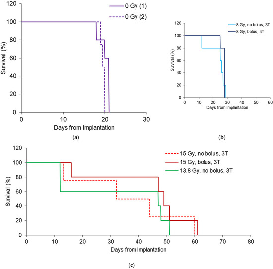
Figure 6.
Survival outcomes for 8 Gy (a) 13.8 Gy (b) and 15 Gy (c) MRT conditions shown in Table 1. All survival curves have n = 5, except 15 Gy 3T (n = 4), to include only rats with tumors >1 mm3.

Table 2.
Survival results for all treatment programs (#1-#6) in Table 1, including mean survival time (MST), median survival time (MeST), increase in mean life span (ILS) and increase in median life span (IMLS). These were measured in days from tumor implantation. Standard error of the mean (SE) also provided for each trial. Log-rank significance of the survival of each group compared to the control was included using MedCalc® Software (version 20). Each treatment condition contained 5 rats.
In all cases except 13.8 Gy MRT, survival was significantly increased due to the irradiation. For 13.8 Gy animals, there were losses after MRT that caused greater variance in the results compared to control animals. The bolus indicates better survival outcomes overall with an increase in IMLS by 67% for rats treated with 15 Gy and 18% for rats treated with 8 Gy. This is likely due to better conformity of the valley dose to reduce survival variation, as there was no significance in the survival between 15 Gy groups with a bolus (p = 0.39, log-rank test). For 8 Gy groups with and without bolus, survival significance was p = 0.36.
As intended by our study design, the overall benefit of the bolus was the reduction in the variance of the mean survival (standard error, SE) and increase in lifespan. For the 15 Gy and 8 Gy groups, the mean increase in life span (ILS) increased by 45% and 21%, respectively. The SE for the 15 Gy cohort was 1.3 times greater than when a bolus was used (9.9 days compared to 7.6, respectively). For 8 Gy cohorts, the SE was 5 times greater without a bolus (3 days compared to 0.6 days with a bolus).
It should be noted that the variation observed in the no bolus cohorts is due to some individuals with >95% valley dose coverage of the tumor, and others without adequate coverage. Figure 7 demonstrates that not only may there be differences in tumor shapes and sizes, but occasionally a ‘natural’ dose modulation occurred in some rats due to skin swelling. This increased the effective depth of the tumor, causing an increase in valley dose and improvement in the valley dose consistency. With the bolus in place, we ensured full target-dose coverage, even for large or shallow tumors.
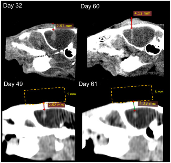
Figure 7.
CT images of rats treated with and without bolus at 15 Gy (treatment programs 5 and 6 in Table 1). CT images were obtained from the Inveon (top) and Somatom (bottom). The depth of the tumor was measured from the top of the rat head to the top of the tumor (lines with crosses), and placement of the bolus is provided to indicate how the overall depth increased (yellow lines—not to scale).
Another finding was that the bolus had direct consequences on the peak and valley doses, and this can be compared to identify which factor is most likely to effect MRT survival. Table 3 shows the analysis from the DVHs of all treatment groups, including the minimum valley dose received to 100% of the tumor volume and the minimum peak dose exposed to the tumor. Table 3 does not show a correlation between the treatment groups’ MST with minimum peak dose (peak dose to 100% of the tumor volume). The bolus reduces the peak dose for 8 Gy and 15 Gy cohorts as expected, but this does not correspond to a decrease in the MST. Instead, the minimum valley dose appears to have the greater correlation to survival. For cohorts with the bolus, the valley dose increased and showed an increase in survival. These relationships are further summarized in Figure 8, which shows the survival of individuals compared to the minimum valley and peak doses that each individual tumor volume received. Both the individuals with and without the bolus are included.

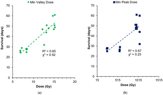
Figure 8.
Comparison of individual survival with the minimum valley dose (a) and minimum peak dose (b) each tumor receives.
Figure 8 indicates that survival increased with the increasing minimum valley dose to the tumor, with a mostly linear fit (92% correlation with chi-squared test). Some outliers remaining may be due to the natural variation in tumor responses, tumor vascularization and oxygenation, and the initial tumor volume, which was not accounted for in this comparison. The dependence of survival on the peak dose is less apparent (25% correlation) than the valley dose, but there is a general increase in survival due to the dose escalation from the 8–15 Gy valley doses prescribed. In the 13.8–15 Gy valley-dose cohorts with 955–1043 Gy peak doses, survival ranged from 32 to 61 days without any linear dependence. For 8 Gy valley-dose cohorts, survival was similar, between 25 and 29 days, while the peak dose varied from 250 to 566 Gy (by 2.6-fold).
This further indicates that the peak dose is not responsible for the survival increase alone, but rather the minimum dose to the tumor associated with the valley dose. This result is likely due to the fact that the cells receiving the peak dose (over 250 Gy in all our treatment groups) were unable to survive. Thus, regardless of the peak dose delivered, these cells did not participate in the tumor’s ability to recover, causing the valley dose to be the most prominent indicator for tumor control.
It is important to note that the peak doses are, however, instrumental in the destruction of the tumor vasculature and destabilizing the tumor microenvironment in MRT. In a comparison of these results to those of a previous conventional 250 kVp X-ray irradiation of 9 L tumors in Fischer rats, those results showed an MST of just 26 days with 15 Gy, and 31 days with 22.5 Gy [40], compared to our 27 days and 45 days survival with 8 Gy and 15 Gy, respectively. MRT peak radiosurgery not only directly destroys tumor cells, but previous studies have linked secondary tumor elimination to the preferential tumor vasculature response towards MRT [18,41,42,43,44]. Tumor vasculature is juvenile and more sensitive to radiation [41], whereas the mature vasculature networks in normal tissue are not permanently affected by microbeams, even up to 1000 Gy [42].
The destruction of the tumor vasculature may largely be similar between our treatment groups, as we delivered damaging peak doses of 250–1000 Gy that were well above the reported threshold for the tumor vasculature radiation resistance of 10 Gy [43].
Perhaps at lower doses, we might observe a stronger survival dependence on the peak dose.
In our work, the single port of MRT exposed just 12.5% of the tumor (and its vasculature) to peak doses, which is a lower percentage than multi-port MRT [10]. Therefore, we may have had less probability of destroying tumor vasculature than other MRT studies, but clearly, we exceeded the MST of the 15 Gy broad beam despite 87.5% of the tumor receiving the 15 Gy dose. We can attribute this to the role of the peak dose.
Variation was noted in our survival and likely linked to the individual tumor condition, including the tumor volume. In particular, we obtained two extremes in individual tumors; one individual had a tumor volume of 0.6 mm3 and survived to 528 days following a 15 Gy dose (shown in previous work [11]), and another with the largest tumor of 8.5 mm3 had a survival of only 32 days despite being in a 15 Gy cohort. This is summarized in Figure 9, showing the individual volumes of the tumor with respect to survival for each treatment-cohort valley dose.

Figure 9.
Individual tumor volumes measured from CT images with respect to individual survival in the 8 Gy, 13.8 Gy and 15 Gy treatment groups.
The 8 Gy treatment, regardless of individual tumor sizes, was not sufficient to increase survival beyond 29 days, and, thus, no dependence of survival on tumor volume was observed for this group. For the higher treatment doses of 13.8–15 Gy, larger tumors tended to have lower survival. This highlights that the tumor volume is a contributing factor to long-term survival following MRT, as a result of marked differences in the tumor microenvironment, including hypoxic cells and hypoxic tumor vasculature.
Hypoxic cells lie dormant within the tumor, and repopulate the tumor after radiotherapy, as they are extremely radiation-resistant in absence of the oxygen that triggers indirect radiation damage [45]. MRT overcomes this radiation resistance with significant direct damage from radiosurgical peak doses, and destabilizes not only the oxic, but also the radiation-resistant hypoxic tumor vasculature that allows tumor angiogenesis [46].
It is possible, therefore, that our valley-dose coverage of 87.5% of the tumor volume could promote tumor repopulation due to the surviving hypoxic tumor cells. These are more numerous in the larger tumors and may nurture tumor recovery, leading to low survival for these individuals, where the dose may otherwise have been successful to destroy oxic tumor cells (valley doses > 8 Gy). We previously found that 8 Gy in the valley produces ~10% survival of oxic 9 L gliosarcoma cells in vitro [11], and so we believe it is not a curative dose for oxic cells, let alone hypoxic cells. Therefore, for 8 Gy doses in vivo, there was no significant dependence on tumor volume and the quantity of hypoxic cells.
To increase the tumor volume affected by the peak, and eliminate more hypoxic tumor cells or hypoxic vasculature, multiport cross-fired MRT methods [10], or nanoparticles [47,48] could be used to further increase the peak dose range of damage.
In this section, we have demonstrated promising outcomes for using a bolus to modulate the unilateral MRT dose as desired for the treatment of preclinical brain cancers. This has benefits for adjusting tumor target doses depending on the tumor’s location in the brain and can be applicable to multiport MRT [10]. We further highlighted the importance of the valley dose in long-term MRT survival using the bolus to modify the peak and valley doses with depth. As the peak and valley doses differ with depth, the peak-to-valley dose-ratio (PVDR) can, therefore, be manipulated using a bolus according to desired treatment requirements. This work has investigated the effect of a 5 mm bolus on the peak and valley for the same field size of 8 × 8 mm2, two different beam qualities, and through a rat’s head volume. For future preclinical studies, MRT peak and valley doses should be simulated through the correct volume to include backscatter components, and with the field size and beam energy desired. We believe the bolus would be useful to modulate valley doses under many conditions; however, the required bolus thickness will need to be assessed on a case-by-case basis.
It is important to note that a bolus increases the MRT valley dose to not only the tumor, but also the healthy brain where tissue sparing is critical. The next section investigates the potential impact of a bolus in unilateral MRT on the healthy brain.
3.3. Dose Modulation and Organs at Risk
DVHs were produced from CT imaging of the whole brain to determine the effect of MRT with and without a bolus. The hippocampus, located 1.8–6.3 mm posterior to the bregma crossing and 2.5–4 deep, is a critical structure in the brain for memory. The hippocampus is also particularly irradiated by our 8 × 8 mm2 treatment field centered at 3.5 mm to the right of the bregma crossing. To estimate the impact to the hippocampus and whole brain, the peak and valley doses were calculated with depth within each volume. Figure 10 shows the DVHs for the hippocampus and whole brain, and Table 4 further summarizes the volume of these critical organs receiving the target dose for each MRT treatment conditions in Table 1.
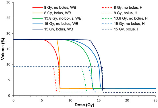
Figure 10.
Dose volume histograms for the hippocampus (H) and whole brain (WB), with and without a bolus according to the treatment conditions in Table 1. Whole brain volumes for the DVH were acquired from the CT imaging. Hippocampus volumes were mapped with a rodent brain atlas [49].

In all cases, the treatment programs without a bolus (2, 4 and 5) produced a lower %Vol of the target dose to the healthy brain. This is because the target valley dose is prescribed to 5.5 mm depth where the valley dose does not build to a maximum (refer to Figure 2). Ultimately, this spares the hippocampus and whole brain from high valley doses compared to the case with a bolus. The bolus instead shifts the valley-dose plateau to cover more of the brain, particularly towards shallower depths with respect to the bregma crossing, and into the somatosensory and motor cortexes.
The whole-brain dose was slightly increased by using a bolus (4–6%). It should be noted that MRT spares a significant amount of the whole brain compared to unidirectional broad beam due to the non-diverging microbeam array. Shaw et al. [50] showed that in single radiation treatments of human brain cancers, the maximum tolerated doses were 24 Gy, 18 Gy, and 15 Gy for tumors less than 20 mm, 21–30 mm, and 31–40 mm in maximum diameter, respectively. For this study, a single conformal exposure of 15 Gy for the treatment of human 40 mm diameter tumors we estimate that a minimum of 30% of the brain would receive a dose of ~15 Gy, which is similar to our study. Rats reportedly tolerate a whole-brain dose of 20 Gy, although with decreased hippocampal neurogenesis and cellular proliferation [51]. However, Yang et al. [51] summarized that cognitive function returned to normal at 60 days post-exposure to 20 Gy, with no pathological changes, and there was a normal brain water content despite increased blood–brain barrier permeability. Rather than the unidirectional approach in our work, cross-firing the MRT field multiple times [10] may offer greater reduction in the maximum whole-brain doses, and instead raise the overall volume of the brain that receives a radiation dose.
The hippocampus received more dose with a bolus (8% more of the total hippocampus volume received the target dose). However, less than 10% of the hippocampus was estimated to be irradiated with 8 or 15 Gy. An indication of radiation tolerance doses for the hippocampus is summarized by Scoccianti et al. [52]. Maximum doses ranged between 12 and 54 Gy, with maximum avoidance volumes requiring <20Gy to 20% of the volume and <7.2 Gy to 40% of the volume. Considering the valley dose alone, we are within these tolerance requirements. However, within the MRT peak, maximum doses of >300 Gy were delivered in 50 μm wide sections onto the hippocampus. We did not observe memory deficits in our qualitative observations of our animals, and MRT has not been shown to cause memory deficits in other work [27]. We hypothesize that the hippocampus tolerance to MRT, therefore, may exceed the current maximum avoidance dose constraints when delivered within micrometer segments. The valley dose is more likely to be the limiting factor, provided it does not exceed the maximum dose constraints given by Scoccianti et al. [52].
3.4. Bolus and Hair Recovery
Finally, we were interested in the effect of the improved MRT method compared to the nominal MRT on hair recovery. The use of a bolus was expected to raise the minimum skin dose from 5.5 to 7.5 Gy and from 8.5 to 14.9 Gy, for 8 Gy and 15 Gy target doses, respectively. Table 5 shows the time taken after MRT to recover hair, and Figure 11 shows the loss of hair and hair regrowth over time for an individual rat receiving 15 Gy target dose with the bolus. MRT did not cause visible skin redness; however, hair was lost in all animals (n = 25) by the 5th day post-MRT. For the 8 Gy groups, hair began to completely return from day 16 post-MRT (survival day 28). However, due to the brain tumor reoccurrence, some rats required euthanasia before the hair fully returned.

Table 5.
Hair recovery after MRT due to each irradiation treatment program (#2-6). Errors refer to subjective assessment of complete hair return, and variation amongst individuals. Living animals assessed only. * For the 8 Gy cohort, hair had begun to return from day 28 after tumor implantation; however, due to euthanasia from tumor symptoms, the full extent of hair recovery could not be determined.
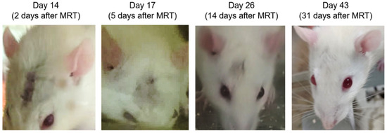
Figure 11.
Examples of hair loss and regrowth over time after MRT for an animal receiving 15 Gy target dose using a bolus.
For treatment doses >13 Gy, hair returned before clinical signs were observed for tumor recurrence. There was no significant difference in hair recovery between 13.8 Gy and 15 Gy, or due to the presence of a bolus. This is promising for the use of a bolus in MRT. Radiotherapy with a bolus increases skin dose [30,31], and we can confirm that this is also the case with the MRT valley dose, and not so with the peak dose, which is 20% less without the bolus. It should be noted that the high dose rates used for MRT (280–6000 Gy/s in-beam) may further facilitate skin-tissue sparing due to the FLASH effect above 40 Gy/s [12].
4. Conclusions
In this study, we have demonstrated how modulation of the unilateral MRT dose can be used to improve tumor control. By simulating the MRT field using Geant4 (verified with dosimetry), we calculated the change in the MRT valley and peak doses with respect to depth for the treatment of rat brain tumors. We found that depending on the location of the tumor with respect to depth, a tumor could receive 20% less dose to some of its volume when prescribing to the nominal implantation depth at 5.5 mm. This was determined by analyzing the tumors of over 30 rats bearing 9 L gliosarcoma tumors at day 11 after implantation. A 5 mm dose-modulating bolus was then used to shift the effective depth of the tumors and ensure the valley dose was consistent across the tumor volume. This improved the valley-dose consistency across the tumor volume and showed improvements in survival of 47% and 18% for the valley doses of 15 Gy and 8 Gy, respectively. We also found that escalating the dose from 8 Gy to 15 Gy increased the survival of 9 L gliosarcoma-bearing rats by 1.7 times. On analyzing the individual valley and peak doses received by tumors across all treatment groups, there was a 92% correlation between the MRT valley dose and survival, and only 25% correlation for the peak dose (chi-squared). Therefore, the MRT valley dose should be considered as a primary factor in long-term survival. The bolus showed that the peak had no significant effect on the survival, and it is likely that peak doses of over hundreds of Gy eliminated all viable tumor cells within the peak in all our treatments. Instead, regions with valley doses are where tumor cells may recover to repopulate the tumor. The use of a bolus was also predicted to increase valley doses to the whole brain and hippocampus, (with up to 8% more of the target valley dose).
As preclinical studies move forward, MRT delivered both unilaterally or in cross fired methods both require consideration of individual tumor coverage and may benefit from the use of a bolus. Our method outlined here can be applied to other cancer targets and treatment conditions. The advantage a bolus presents is in changing the valley dose as required relative to the peak (or altering the PVDR), which may be also become useful to modulate the dose rate in the peak or valley. MRT dose modulation using a bolus can be applied when the peak and valley doses with respect to depth can be calculated, as doses will depend on treatment conditions, including field size, target volumes and beam energy. Bolus thickness, if any is required, should be determined on a case-by-case basis.
Supplementary Materials
The following supporting information can be downloaded at: https://www.mdpi.com/article/10.3390/radiation3040015/s1, Figure S1: Tumor volume and valley dose coverage with depth
Author Contributions
Conceptualization: E.E., S.C., M.L. and M.T.; methodology: E.E., M.T., S.E.V., M.V., J.R.P., N.L., J.A.D., M.B., M.C., A.D., M.L. and S.C.; software: J.R.P., M.C., A.D., A.W.S., M.B. and M.L.; formal analysis: E.E. and J.R.P.; investigation: E.E., S.E.V., N.L., M.L., J.R.P., M.V., A.K., M.T., A.O. and J.A.D.; data curation: E.E.; writing—original draft preparation: E.E.; writing—review and editing: E.E., J.R.P., S.E.V., M.L., S.C. and M.T.; visualization: E.E. and J.R.P.; supervision: M.T., M.L., S.C. and A.R.; project administration:, M.T., M.L. and S.C.; resources: M.L., M.T., A.R. and S.C.; funding acquisition: M.T., M.L. and A.R. All authors have read and agreed to the published version of the manuscript.
Funding
We acknowledge the financial support of the Australian Government Research Training Program Scholarship, Australian Synchrotron travel funding (proposals 12955, 14127, and 15023), and Australian National Health & Medical Research Council (APP1084994 and APP1093256).
Institutional Review Board Statement
The animal study protocol was approved by the Ethics Committees of the University of Wollongong (AE17/05, 2017), Australian Synchrotron and ANSTO (AS-2017-01, 2017).
Informed Consent Statement
Not applicable.
Data Availability Statement
The data presented in this study are available on request from the corresponding author. The data are not publicly available due to data Embargo and intellectual protection.
Acknowledgments
We acknowledge the time in and access to the lab facilities at Building 32 at the University of Wollongong (UOW), Wollongong, Australia, the Australian Synchrotron and Australian Nuclear Science and Technology Organisation (ANSTO), and the UOW Animal House. The authors acknowledge the facilities and scientific and technical assistance of the National Imaging Facility (NIF), a National Collaborative Research Infrastructure Strategy (NCRIS) capability at Monash Biomedical Imaging (MBI), a Technology Research Platform at Monash University. We are grateful to all assisting personnel including UOW Animal Welfare Officer Sarah Toole, Beamline Veterinary Scientist Mitzi Klein, Daniel Häusermann (principal scientist on the IMBL), Michael de Veer (National Imaging Facility fellow, and head of Preclinical Imaging at the MBI), Tara Sepehrizadeh, MBI, all UOW animal research and teaching staff, and IMBL staff. We acknowledge and thank glioblastoma multiforme patient advocate David Wood for his support of this research. We acknowledge the support of the Monash, Australian Synchrotron and UOW Animal Ethics Committees.
Conflicts of Interest
The authors declare no conflict of interest.
References
- Iacob, G.; Dinca, E.B. Current data and strategy in glioblastoma multiforme. J. Med. Life 2009, 2, 386–393. [Google Scholar] [PubMed]
- Osuka, S.; Van Meir, E.G. Overcoming therapeutic resistance in glioblastoma: The way forward. J. Clin. Investig. 2017, 127, 415–426. [Google Scholar] [CrossRef] [PubMed]
- Kowalski-Chauvel, A.; Modesto, A.; Gouaze-andersson, V.; Baricault, L.; Gilhodes, J.; Delmas, C.; Lemarie, A.; Toulas, C.; Cohen-Jonathan-Moyal, E.; Seva, C. Alpha-6 integrin promotes radioresistance of glioblastoma by modulating DNA damage response and the transcription factor Zeb1. Cell Death Dis. 2018, 9, 872. [Google Scholar] [CrossRef]
- Del Maestro, R. A History of Neuro–Oncology; Montreal DW Medical Consulting Inc.: Westmount, QC, Canada, 2006. [Google Scholar]
- Combs, S.E.; Widmer, V.; Thilmann, C.; Hof, H.; Debus, J.; Schulz-Ertner, D. Stereotactic radiosurgery (SRS): Treatment option for recurrent glioblastoma multiforme (GBM). Cancer 2005, 104, 2168–2173. [Google Scholar] [CrossRef] [PubMed]
- Nwokedi, E.C.; DiBiase, S.J.; Jabbour, S.; Herman, J.; Amin, P.; Chin, L.S. Gamma Knife Stereotactic Radiosurgery for Patients with Glioblastoma Multiforme. Neurosurgery 2002, 50, 41–47. [Google Scholar]
- Potez, M.; Bouchet, A.; Flaender, M.; Rome, C.; Collomb, N.; Grotzer, M.; Krisch, M.; Djonov, V.; Balosso, J.; Brun, E.; et al. Synchrotron X-Ray Boost Delivered by Microbeam Radiation Therapy After Conventional X-Ray Therapy Fractionated in Time Improves F98 Glioma Control. Int. J. Radiat. Oncol. Biol. Phys. 2020, 107, 360–369. [Google Scholar] [CrossRef]
- Engels, E.; Lerch, M.; Tehei, M.; Konstantinov, K.; Guatelli, S.; Rosenfeld, A.; Corde, S. Synchrotron activation radiotherapy: Effects of dose-rate and energy spectra to tantalum oxide nanoparticles selective tumour cell radiosensitization enhancement. J. Phys. Conf. Ser. 2017, 777, 012011. [Google Scholar] [CrossRef]
- Eling, L.; Bouchet, A.; Nemoz, C.; Djonov, V.; Balosso, J.; Laissue, J.; Bräuer-Krisch, E.; Adam, J.F.; Serduc, R. Ultra high dose rate Synchrotron Microbeam Radiation Therapy. Preclinical evidence in view of a clinical transfer. Radiother. Oncol. 2019, 139, 56–61. [Google Scholar] [CrossRef] [PubMed]
- Eling, L.; Bouchet, A.; Ocadiz, A.; Adam, J.F.; Kershmiri, S.; Elleaume, H.; Krisch, M.; Verry, C.; Laissue, J.A.; Balosso, J.; et al. Unexpected Benefits of Multiport Synchrotron Microbeam Radiation Therapy for Brain Tumors. Cancers 2021, 13, 936. [Google Scholar] [CrossRef]
- Engels, E.; Li, N.; Davis, J.; Paino, J.; Cameron, M.; Dipuglia, A.; Vogel, S.; Valceski, M.; Khochaiche, A.; O’Keefe, A.; et al. Toward personalized synchrotron microbeam radiation therapy. Sci. Rep. 2020, 10, 8833. [Google Scholar] [CrossRef]
- Vozenin, M.C.; Hendry, J.H.; Limoli, C.L. Biological Benefits of Ultra-high Dose Rate FLASH Radiotherapy: Sleeping Beauty Awoken. Clin. Oncol. 2019, 31, 407–415. [Google Scholar] [CrossRef]
- Slatkin, D.N.; Spanne, P.; Dilmanian, F.A.; Sandborg, M. Microbeam radiation therapy. Med. Phys. 1992, 19, 1395. [Google Scholar] [CrossRef]
- Bräuer-Krisch, E.; Serduc, R.; Siegbahn, E.A.; Le Duc, G.; Prezado, Y.; Bravin, A.; Blattmann, H.; Laissue, J.A. Effects of pulsed, spatially fractionated, microscopic synchrotron X-ray beams on normal and tumoral brain tissue. Mutat. Res. 2010, 704, 160–166. [Google Scholar] [CrossRef] [PubMed]
- Bräuer-Krisch, E.; Adam, J.F.; Alagoz, E.; Bartzsch, S.; Crosbie, J.; DeWagter, C.; Dipuglia, A.; Donzelli, M.; Doran, S.; Fournier, P.; et al. Medical physics aspects of the synchrotron radiation therapies: Microbeam radiation therapy (MRT) and synchrotron stereotactic radiotherapy (SSRT). Phys. Med. 2015, 31, 568–583. [Google Scholar] [CrossRef]
- Stevenson, A.W.; Crosbie, J.C.; Hall, C.J.; Häusermann, D.; Livingstone, J.; Lye, J.E. Quantitative characterization of the X-ray beam at the Australian Synchrotron Imaging and Medical Beamline (IMBL). J. Synchrotron Radiat. 2017, 24, 110–141. [Google Scholar] [CrossRef]
- Dilmanian, F.A.; Qu, Y.; Feinendegen, L.E.; Peña, L.A.; Bacarian, T.; Henn, F.A.; Kalef-Ezra, J.; Liu, S.; Zhong, Z.; McDonald, J.W. Tissue-sparing effect of x-ray microplanar beams particularly in the CNS: Is a bystander effect involved? Exp. Hematol. 2007, 35 (Suppl. S1), 69–77. [Google Scholar] [CrossRef]
- Bouchet, A.; Lemasson, B.; Le Duc, G.; Maisin, C.; Bräuer-Krisch, E.; Siegbahn, E.A.; Renaud, L.; Khalil, E.; Rémy, C.; Poillot, C.; et al. Preferential effect of synchrotron microbeam radiation therapy on intracerebral 9L gliosarcoma vascular networks. Int. J. Radiat. Oncol. Biol. Phys. 2010, 78, 1503–1512. [Google Scholar] [CrossRef]
- Bouchet, A.; Lemasson, B.; Christen, T.; Potez, M.; Rome, C.; Coquery, N.; Le Clec’h, C.; Moisan, A.; Bräuer-Krisch, E.; Le Duc, G.; et al. Synchrotron microbeam radiation therapy induces hypoxia in intracerebral gliosarcoma but not in the normal brain. Radiother. Oncol. 2013, 108, 143–148. [Google Scholar] [CrossRef]
- Sabatasso, S.; Fernandez-Palomo, C.; Hlushchuk, R.; Fazzari, J.; Tschanz, S.; Pellicioli, P.; Krisch, M.; Laissue, J.A.; Djonov, V. Transient and Efficient Vascular Permeability Window for Adjuvant Drug Delivery Triggered by Microbeam Radiation. Cancers 2021, 13, 2103. [Google Scholar] [CrossRef]
- Adam, J.F.; Balosso, J.; Bayat, S.; Berkvens, P.; Berruyer, G.; Bräuer-Krisch, E.; Brochard, T.; Chamel, G.; Desagneaux, A.; Drevon-Gaud, R.; et al. Toward Neuro-Oncologic Clinical Trials of High-Dose-Rate Synchrotron Microbeam Radiation Therapy: First Treatment of a Spontaneous Canine Brain Tumor. Int. J. Radiat. Oncol. Biol. Phys. 2022, 113, 967–973. [Google Scholar] [CrossRef]
- Cameron, M.; Cornelius, I.; Cutajar, D.; Davis, J.A.; Rosenfeld, A.; Lerch, M.; Guatelli, S. Comparison of phantom materials for use in quality assurance of microbeam radiation therapy. J. Synchrotron Radiat. 2017, 24, 866–876. [Google Scholar] [CrossRef] [PubMed]
- Davis, J.A.; Paino, J.R.; Dipuglia, A.; Cameron, M.; Siegele, R.; Pastuovic, Z.; Petasecca, M.; Perevertaylo, V.L.; Rosenfeld, A.B.; Lerch, M.L.F. Characterisation and evaluation of a PNP strip detector for synchrotron microbeam radiation therapy. Biomed. Phys. Eng. Express 2018, 4, 044002. [Google Scholar] [CrossRef]
- Dipuglia, A.; Cameron, M.; Davis, J.A.; Cornelius, I.M.; Stevenson, A.W.; Rosenfeld, A.B.; Petasecca, M.; Corde, S.; Guatelli, S.; Lerch, M.L.F. Validation of a Monte Carlo simulation for Microbeam Radiation Therapy on the Imaging and Medical Beamline at the Australian Synchrotron. Sci. Rep. 2019, 9, 17696. [Google Scholar] [CrossRef]
- Siegbahn, E.A.; Stepanek, J.; Bräuer-Krisch, E.; Bravin, A. Determination of dosimetrical quantities used in microbeam radiation therapy (MRT) with Monte Carlo simulations. Med. Phys. 2006, 33, 3248–3259. [Google Scholar] [CrossRef] [PubMed]
- Nettelbeck, H.; Takacs, G.J.; Lerch, M.L.; Rosenfeld, A.B. Microbeam radiation therapy: A Monte Carlo study of the influence of the source, multislit collimator, and beam divergence on microbeams. Med. Phys. 2009, 36, 447–456. [Google Scholar] [CrossRef] [PubMed]
- Schültke, E.; Juurlink, B.H.; Ataelmannan, K.; Laissue, J.; Blattmann, H.; Bräuer-Krisch, E.; Bravin, A.; Minczewska, J.; Crosbie, J.; Taherian, H.; et al. Memory and survival after microbeam radiation therapy. Eur. J. Radiol. 2008, 68 (Suppl. S3), S142–S146. [Google Scholar] [CrossRef]
- Schültke, E.; Balosso, J.; Breslin, T.; Cavaletti, G.; Djonov, V.; Esteve, F.; Grotzer, M.; Hildebrandt, G.; Valdman, A.; Laissue, J. Microbeam radiation therapy—Grid therapy and beyond: A clinical perspective. Br. J. Radiol. 2017, 90, 20170073. [Google Scholar] [CrossRef]
- Di Pietro, P.; Bucci, D.; De Fusco, A.; Le Duc, G.; Bräuer-Krisch, E.; Battaglia, G.; Romanelli, P.; Bravin, A. Evaluation of long-term effects of synchrotron-generated microbeams on rat hippocampal neurogenesis. Radiother. Oncol. 2016, 118, S14–S15. [Google Scholar] [CrossRef]
- Low, J.M.; Lee, N.J.H.; Sprow, G.; Chlebik, A.; Olch, A.; Darrow, K.; Bowlin, K.; Wong, K.K. Scalp and Cranium Radiation Therapy Using Modulation (SCRUM) and Bolus. Adv. Radiat. Oncol. 2020, 5, 936–942. [Google Scholar] [CrossRef] [PubMed]
- Kudchadker, R.J.; Antolak, J.A.; Morrison, W.H.; Wong, P.F.; Hogstrom, K.R. Utilization of custom electron bolus in head and neck radiotherapy. J. Appl. Clin. Med. Phys. 2003, 4, 321–333. [Google Scholar] [CrossRef]
- National Health and Medical Research Council. Australian Code for the Care and Use of Animals for Scientific Purposes, 8th ed.; National Health and Medical Research Council: Canberra, Australia, 2013. [Google Scholar]
- Cunliffe-Beamer, T. Surgical Techniques. Guidelines for the Well Being of Rodents in Research. Bethesda, Maryland; Scientists Center for Animal Welfare: Bend, OR, USA, 1990; pp. 86–92. [Google Scholar]
- Pritchett-Corning, K.R.; Mulder, G.B.; Luo, Y.; White, W.J. Principles of Rodent Surgery for the New Surgeon. J. Vis. Exp. 2011, 47, e2586. [Google Scholar]
- Paino, J.; Barnes, M.; Engels, E.; Davis, J.; Guatelli, S.; de Veer, M.; Hall, C.; Häusermann, D.; Tehei, M.; Corde, S.; et al. Incorporating Clinical Imaging into the Delivery of Microbeam Radiation Therapy. Appl. Sci. 2021, 11, 9101. [Google Scholar] [CrossRef]
- Petasecca, M.; Cullen, A.; Fuduli, I.; Espinoza, A.; Porumb, C.; Stanton, C.; Aldosari, A.H.; Brauer-Krisch, E.; Requardt, H.; Bravin, A.; et al. X-Tream: A novel dosimetry system for Synchrotron Microbeam Radiation Therapy. J. Instrum. 2012, 7, P07022. [Google Scholar] [CrossRef]
- Fournier, P.; Cornelius, I.; Dipuglia, A.; Cameron, M.; Davis, J.A.; Cullen, A.; Petasecca, M.; Rosenfeld, A.B.; Bräuer-Krisch, E.; Häusermann, D.; et al. X-Tream dosimetry of highly brilliant X-ray microbeams in the MRT hutch of the Australian Synchrotron. Radiat. Meas. 2017, 106, 405–411. [Google Scholar] [CrossRef][Green Version]
- Agostinelli, S.; Allison, J.; Amako, K.; Apostolakis, J.; Araujo, H.; Arce, P.; Asai, M.; Axen, D.; Banerjee, S.; Barrand, G.; et al. Geant4—A simulation toolkit. Nucl. Instrum. Methods Phys. Res. Sect. A Accel. Spectrometers Detect. Assoc. Equip. 2003, 505, 250–303. [Google Scholar] [CrossRef]
- Barnes, M.J.; Paino, J.; Day, L.R.; Butler, D.; Hausermann, D.; Pelliccia, D.; Crosbie, J.C. SyncMRT: A solution to image-guided synchrotron radiotherapy for quality assurance and pre-clinical trials. J. Synchrotron Radiat. 2022, 29, 1074–1084. [Google Scholar] [CrossRef] [PubMed]
- Joel, D.D.; Fairchild, R.G.; Laissue, J.A.; Saraf, S.K.; Kalef-Ezra, J.A.; Slatkin, D.N. Boron neutron capture therapy of intracerebral rat gliosarcomas. Proc. Natl. Acad. Sci. USA 1990, 87, 9808–9812. [Google Scholar] [CrossRef]
- Brönnimann, D.; Bouchet, A.; Schneider, C.; Potez, M.; Serduc, R.; Bräuer-Krisch, E.; Graber, W.; von Gunten, S.; Laissue, J.A.; Djonov, V. Synchrotron microbeam irradiation induces neutrophil infiltration, thrombocyte attachment and selective vascular damage in vivo. Sci. Rep. 2016, 6, 33601. [Google Scholar] [CrossRef]
- Bouchet, A.; Serduc, R.; Laissue, J.A.; Djonov, V. Effects of microbeam radiation therapy on normal and tumoral blood vessels. Phys. Med. 2015, 31, 634–641. [Google Scholar] [CrossRef]
- Song, C.W.; Terezakis, S.; Park, W.Y.; Paek, S.H.; Kim, M.S.; Cho, L.C.; Griffin, R.J. Preferential Tumor Vascular Damage Is the Common Antitumor Mechanism of High-Dose Hypofractionated Radiation Therapy: SABR, Spatially Fractionated Radiation Therapy, and FLASH Radiation Therapy. Int. J. Radiat. Oncol. Biol. Phys. 2023, 17, 701–704. [Google Scholar] [CrossRef]
- Kozin, S.V. Vascular damage in tumors: A key player in stereotactic radiation therapy? Trends Cancer 2022, 8, 806–819. [Google Scholar] [CrossRef]
- Menegakis, A.; Klompmaker, R.; Vennin, C.; Arbusà, A.; Damen, M.; van den Broek, B.; Zips, D.; van Rheenen, J.; Krenning, L.; Medema, R.H. Resistance of Hypoxic Cells to Ionizing Radiation Is Mediated in Part via Hypoxia-Induced Quiescence. Cells 2021, 10, 610. [Google Scholar] [CrossRef] [PubMed]
- Koonce, N.A.; Levy, J.; Hardee, M.E.; Jamshidi-Parsian, A.; Vang, K.B.; Sharma, S.; Raleigh, J.A.; Dings, R.P.; Griffin, R.J. Targeting Artificial Tumor Stromal Targets for Molecular Imaging of Tumor Vascular Hypoxia. PLoS ONE 2005, 10, e0135607. [Google Scholar] [CrossRef]
- Le Duc, G.; Miladi, I.; Alric, C.; Mowat, P.; Bräuer-Krisch, E.; Bouchet, A.; Khalil, E.; Billotey, C.; Janier, M.; Lux, F.; et al. Toward an image-guided microbeam radiation therapy using gadolinium-based nanoparticles. ACS Nano 2011, 5, 9566–9574. [Google Scholar] [CrossRef]
- Engels, E.; Corde, S.; McKinnon, S.; Incerti, S.; Konstantinov, K.; Rozenfeld, A.; Tehei, M.; Lerch, M.; Guatelli, S. Optimizing dose enhancement with Ta2O5 nanoparticles for synchrotron microbeam activated radiation therapy. Phys. Med. 2016, 32, 1852–1861. [Google Scholar] [CrossRef] [PubMed]
- Paxinos, G.; Watson, C. The Rat Brain in Stereotaxic Coordinates, 6th ed.; Academic Press: Cambridge, MA, USA; Elsevier: Amsterdam, The Netherlands, 2007. [Google Scholar]
- Shaw, E.; Scott, C.; Souhami, L.; Dinapoli, R.; Kline, R.; Loeffler, J.; Farnan, N. Single dose radiosurgical treatment of recurrent previously irradiated primary brain tumors and brain metastases: Final report of RTOG protocol 90-05. Int. J. Radiat. Oncol. Biol. Phys. 2000, 47, 291–298. [Google Scholar] [CrossRef] [PubMed]
- Yang, L.; Yang, J.; Guoqian, L.; Yi, L.; Rong, W.; Cheng, J.; Tang, Y. Pathophysiological Responses in Rat and Mouse Models of Radiation-Induced Brain Injury. Mol. Neurobiol. 2017, 54, 1022–1032. [Google Scholar] [CrossRef] [PubMed]
- Scoccianti, S.; Detti, B.; Gadda, D.; Greto, D.; Furfaro, I.; Meacci, F.; Simontacchi, G.; Di Brina, L.; Bonomo, P.; Giacomelli, I.; et al. Organs at risk in the brain and their dose-constraints in adults and in children: A radiation oncologist’s guide for delineation in everyday practice. Radiother. Oncol. 2015, 114, 230–238. [Google Scholar] [CrossRef]
Disclaimer/Publisher’s Note: The statements, opinions and data contained in all publications are solely those of the individual author(s) and contributor(s) and not of MDPI and/or the editor(s). MDPI and/or the editor(s) disclaim responsibility for any injury to people or property resulting from any ideas, methods, instructions or products referred to in the content. |
© 2023 by the authors. Licensee MDPI, Basel, Switzerland. This article is an open access article distributed under the terms and conditions of the Creative Commons Attribution (CC BY) license (https://creativecommons.org/licenses/by/4.0/).