Article

Optical Fiber-Based Monitoring of X-ray Pulse Series from a Linear Accelerator

1
CEA, DAM, DIF, F-91297 Arpajon, France
2
Laboratoire Hubert Curien, Université Jean Monnet, CNRS 5516, IOGS, F-42000 St Etienne, France
3
PhLAM (Physique des Lasers Atomes et Molécules), Université de Lille, CNRS, UMR 8523, F-59000 Lille, France
4
CEA, CEG, F-46500 Gramat, France
*
Author to whom correspondence should be addressed.
Radiation 2022, 2(1), 17-32; https://doi.org/10.3390/radiation2010002
Submission received: 10 November 2021 / Revised: 17 December 2021 / Accepted: 23 December 2021 / Published: 28 December 2021

Abstract

:

Simple Summary

This study demonstrated the potential of a cerium-doped optical fiber (11 cm in length) to monitor in real-time a pulsed (4.8 µs pulse duration) or quasi-continuous X-ray source. The developed system relied on the radiation-induced emission within this radio-sensitive optical fiber and can serve as pulse counter or pulse tracker. Furthermore, the measured radioluminescence linearly depended on the dose rate range delivered by the pulsed bremsstrahlung X-ray source and could then serve, after calibration, to characterize the time profile of the photon flux. Thanks to the fast luminescence decay time of cerium and the selected instrumentation, the flash structure of the X-ray ORIATRON facility was characterized.

Abstract

We investigated in this work the radioluminescence properties of a Ce-doped multimode silica-based optical fiber (core diameter of 50 µm) manufactured by the sol–gel technique when exposed to the high-energy X-rays (~600 keV) of the ORIATRON facility of CEA. We demonstrated its potential to monitor in real-time the beam characteristics of this facility that can either operate in a pulsed regime (pulse duration of 4.8 µs, maximum repetition rate of 250 Hz) or in a quasi-continuous mode. The radiation-induced emission (radioluminescence and a minor Cerenkov contribution) linearly grew with the dose rate in the 15–130 mGy(SiO2)/s range, and the afterglow measured after each pulse was sufficiently limited to allow a clear measurement of pulse trains. A sensor with ~11 cm of sensitive Ce-doped fiber spliced to rad-hard fluorine-doped optical fiber, for the emitted light transport to the photomultiplier tube, exhibited interesting beam monitoring performance, even if the Cerenkov emission in the transport fiber was also considered (~5% of the signal). The beam monitoring potential of this class of optical fiber was demonstrated for such facilities and the possibilities of extending the dose rate range are discussed based on possible architecture choices such as fiber type, length or size.

1. Introduction

A variety of radiation sources have been developed these last decades to satisfy the diversity of applications exploiting radiation–matter interactions. Fundamental research needs accelerator complexes with specific requests such as high energy, high luminosity and high beam current, as for example the Large Hadron Collider at CERN [1]. For medical applications, the proton-therapy and radiotherapy tools have evolved, resulting in a diversity of systems from radioactive sources, from X-ray tubes to ion beam accelerators. These radiation systems are optimized to become more compact and adapted to industrial requests. They can deliver either continuous or pulsed beams. As an example, the high energy physics facilities or the space industry need to perform radiation ageing and radiation testing of electronic components [2,3] to predict the cumulative dose effects on their performance and to imagine ways to improve their radiation tolerance. For such applications, both transient and steady state tests are carried out to understand the effects of dose rate and cumulated dose regarding medical applications. In addition, therapies using radiation to cure tumor cells are continuously improved for patient benefit, and today a lot of research is in progress to assess the potential of pulsed beams for FLASH therapy [4]. All of these tools need dosimetry systems to accurately measure the deposited energy to ensure the highest treatment efficiency. For all of these applications, beam control and monitoring of several parameters are crucial: energy, beam spatial distribution, flux (dose rate) and fluence (dose). Because of the diversity of existing facilities, many diagnostics are still under development to monitor and characterize the various beams. Among the investigated technologies, one can cite MOSFET detector [5] and scintillating devices [6]. For continuous X-ray machines, ready-for-use radiochromic films [7] or ionizing chambers [8] are commonly used for dosimetry. For FLASH dosimetry, LiF-based thermoluminescence sensors are usually considered thanks to their ability to measure the post-irradiation dose [9] in both steady state and pulsed conditions [10]. To design a reliable dosimeter, many conditions must be validated in terms of accuracy, spatial resolution, energy and angular independency, repeatability and finally linearity in the selected range of the measure (dose, dose rate, kerma, etc.). However, even more criteria have to be considered for pulsed beams for which the pulse counting and the pulse characteristics (duration, time structure, dose, etc.) are also important to monitor. For patient treatment by radiation, the exposure is fractioned in one or multiple irradiations strongly varying in terms of dose rate or dose [11]. To cover all the ranges of interest, specific dosimeters, able to operate over large domains of dose or dose rate, have to be developed.
For all of these aspects, optical fibers have interesting features for beam instrumentation or even dosimetry. With very small dimensions, angular independence provided by a sensor’s cylindrical geometry and immunity to electromagnetic perturbation, specialty optical fibers are well suited for radiation detection. By changing their core and cladding compositions through their doping with appropriate chemical elements such as phosphorous (P), fluorine (F), nitrogen (N), cerium (Ce), or gadolinium (Gd), their radiation behaviors can be tuned, resulting in very radiation-sensitive materials.
Three main radiation effects are known when a silica-based optical fiber is exposed to radiation [12]. The first one is compaction and appears at high ionizing dose levels (higher than 1 MGy) or at very high neutron fluences (>1019 n.cm−2 [13]); such environments are not part of this paper. The second one corresponds to the optical fiber darkening, which results in a decrease in its transparency with the dose. This effect is named radiation-induced attenuation or RIA [12]. RIA is explained by the generation of microscopic point defects [14] in the amorphous silica matrix. These defects, or color centers, are at the origin of absorption bands that increase the fiber attenuation. In other words, radiation reduces a fiber’s capacity to transport signals. This phenomenon depends on many parameters such as the deposited dose, the dose rate and the fiber composition. RIA of radiation-sensitive fibers has been characterized for different compositions under steady states 40 keV X-ray continuous beam [15], 6 MV and 15 MV X-rays [16], γ-rays [17], 74 MeV protons continuous beam [17,18], 14 MeV neutrons and even pulsed X-rays [17,19]. One of the most efficient methods for monitoring doses from 0.1 to 500 Gy consists in measuring the infrared RIA of P-doped single-mode fibers [20,21]. Aluminosilicate optical fibers are also strongly radiation sensitive, and a recent study [22] showed promising results for radiation detection. The phosphosilicate fibers are deployed in international facilities such as CHARM [23] or SPS [24] at CERN to perform distributed dose measurements. However, when the objective is to keep the fiber transmission at the highest level under irradiation, RIA impact should be mitigated. The optical fiber material can be radiation hardened by reducing the concentration impurities or using fluorine to adjust the silica refractive index [25]. However, other dopants are also interesting for this aspect, e.g., it was shown that the Ce-codoping of rare-earth-doped optical fibers efficiently limits the infrared RIA [26,27].
The third phenomenon is radiation-induced emission (RIE) [12]—the emission of light by radiation within the fiber. RIE is partially guided into the waveguide up to the detector. RIE comprises the contributions from both Cerenkov radiation and radiation-induced luminescence (RIL). Cerenkov radiation [28] is produced by the pounding of a charged particle faster than light in a given medium [29]. The result is an electromagnetic echo following the particle trajectory through the medium. In the case of an optical fiber, the produced photons can be guided along the fiber core up to the detector of the instrumentation chain. To produce Cerenkov photons, the charged particle passing through the matter needs to reach an energy threshold dependent on its refractive index. The Cerenkov photon spectrum varies, as shown in Equation (1) [29,30,31]:
2 N λ = 4 π 2 e 2 c h ( 1 1 β 2 n 2 ( λ ) ) 1 λ 2
where N is Cerenkov photons,   is the medium thickness interacting with the impacting particle, λ is the photon wavelength from the visible to the far UV, h is the Planck constant, e is the elementary charge, β = v/c is the relative velocity of the charged particle and n(λ) is the refractive index of the medium. The Cerenkov photon production depends on the particle flux and is exactly synchronized with the irradiation. It could be exploited for specific radiation detection applications, such as in medicine [32]. Cerenkov could represent a non-negligible part of the RIE in optical fiber irradiated with sup-MeV charged particles or photons. By an appropriate doping of the silica matrix, luminescence can also be observed under irradiation. Depending on the stimulation source, several mechanisms are distinguished: photoluminescence [33], thermoluminescence (TL) or optically stimulated luminescence (OSL) [34]. All of these mechanisms are explained by the presence of additional energy states in the silica band gap [35]. Radiation induces the transition of electrons from the valence band to the conduction band. However, some of these electrons will be trapped by new energy levels considered as metastable. In some case, their detrapping leads to luminescence at an energy depending on the energy gap between the considered levels, e.g., trap levels as in the Cerium case between Ce4+ considered as an electron trap and Ce3+ states considered as recombination center or between excited Ce3+ states and fundamental Ce3+ states [35]. As for Cerenkov emission, the luminescence intensity depends on the dose rate and can then be exploited for dosimetry applications in radiotherapy or proton therapy applications [36,37].
In this study, we evaluated the performance of a sensing probe consisting in a short length of Ce-doped optical fiber (50 µm core diameter) spliced to a radiation-resistant transport F-doped fiber. We show that this probe allowed the real-time monitoring of pulsed or quasi-continuous X-ray beams. The small size of the sensitive volume represents an advantage for the spatial mapping of the X-ray flux. Moreover, thanks to the fast time decay of the Ce3+ ions luminescence, this sensor can count the pulse number and provide the dose per pulse.

2. Materials and Methods

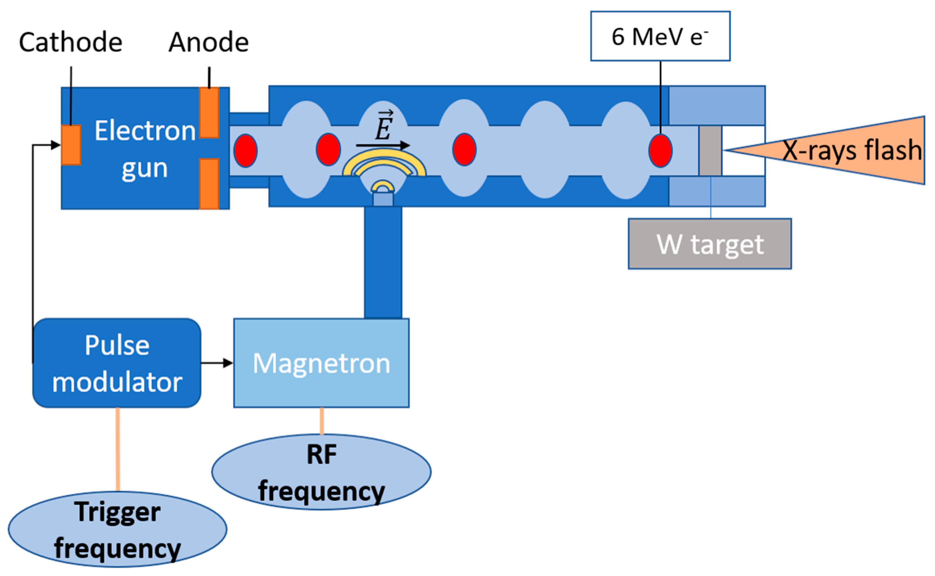
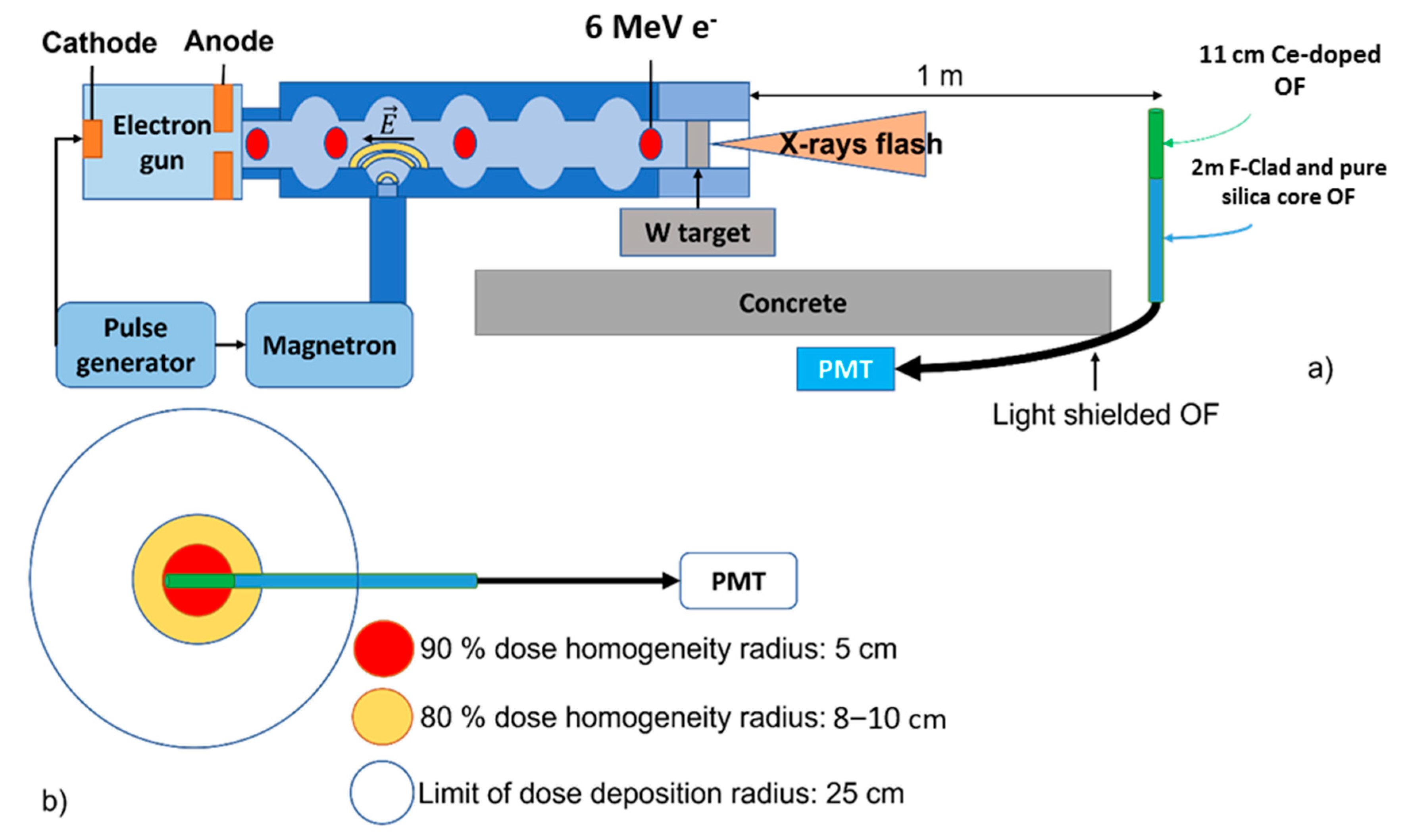
2.1. Irradiation Facility Description

This irradiation campaign was performed at the ORIATRON facility of CEA at Gramat in France [38,39]. This irradiator is a pulsed radiofrequency (RF) electron source, illustrated in Figure 1.
The electrons are produced by triggering a cathode with an electrical current pulse. The electric field taking place in the electron source cavity leads to the extraction and the drift of electrons towards an RF cavity. By the same electric trigger sent to the cathode, a magnetron is turned on and generates an RF electric field propagating from the magnetron cavity towards the RF cavity. The effect of the magnetron RF field on the electrons is double; first a spatial modulation of the electron beam shapes it in bunches, and second an acceleration of the electron bunches up to an energy peaked at 6 MeV.
The modulation of the electron bunch provides an initial pulse length of 4.8 µs. Each single bunch is repeated with a trigger frequency. Two pulsed regimes are available. The first one, called pulsed mode, produces a defined number of electron bunches at a maximum rate of 250 pulses per second. The second mode, called quasi-continuous mode, is an automatization of the pulse production for a delay defined by the user set by a trigger frequency between 25 Hz and 195 Hz. The beam nature can be modified by adding a tungsten target to produce X-rays with a distributed energy peaking around 600 keV, as illustrated in Figure 2 [38,39]. This configuration was used in this study. The X-ray beam characteristics follow the same regime as the electron beam interacting with the target. With the nominal parameters set at 1 m from the target, and a pulse temporal duration of 4.8 µs (full-width at half-maximum (FWHM)), the delivered X-ray dose reaches 6.8 × 10⁻⁴ Gy(SiO2) per pulse. This is given for a trigger frequency of 195 Hz and a dose rate of ~130 mGy(SiO2)/s measured with a reference ionizing chamber (PTW Farmer 30013 [40]).

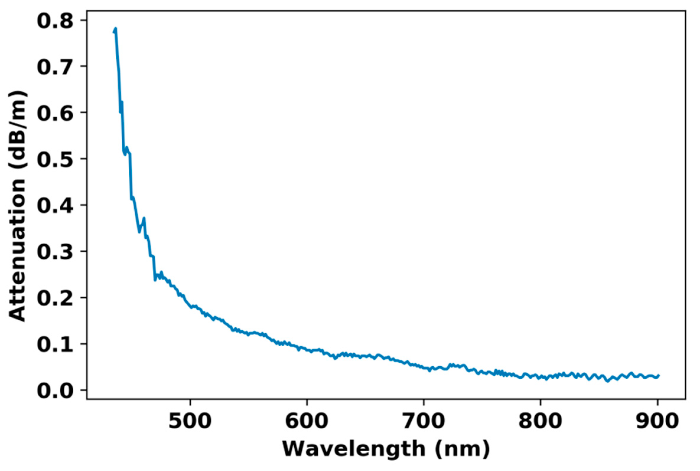
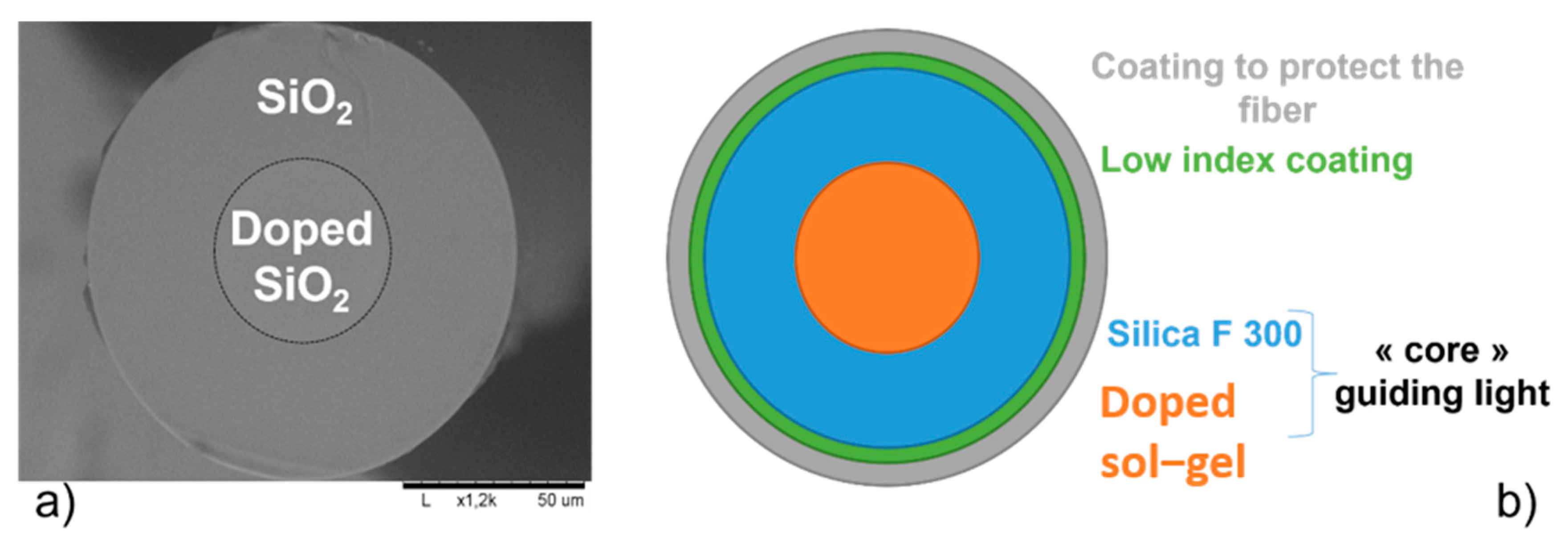
2.2. Description of the Fiber-Based Sensor

Several luminescence bands are associated with cerium ions. In bulk and powder samples, the authors of [43] reported one emission band centered at 460 nm (2.70 eV) that is also observed in optical fiber. This emission is associated with the 5d–4f transition of the Ce3+ ion and is associated with a decay time of 55 ns. In an air-clad Ce-doped optical fiber [44], PL (photoluminescence) measurements, under UV excitation, revealed an emission band centered at 450 nm (2.75 eV) with a decay time of ~84 ns, in agreement with previous studies [44,45].
The tested Ce-doped optical fiber was developed by the technological platform FiberTech Lille of the PhLAM laboratory, France. First, a cerium-doped silica glass rod was fabricated using the sol–gel method, as described in [46]. The obtained glassy rod was drawn down to millimeter-sized canes. After etching with HF and sleeving into F300 silica tube, a final drawing leads to an optical fiber with a diameter of about 125 µm, within which the Ce-doped core zone has a diameter of about 50 µm. The fiber structure is illustrated by the SEM transverse cross-section image presented in Figure 3a. As the cerium doping does not sufficiently change the refractive index of the silica to ensure the light guidance, a 30 µm thick low-refractive index coating was added for this purpose. To protect the optical fiber, an external coating was adjusted with a larger diameter of 340 µm. The whole fiber structure is schematically illustrated in Figure 3b.
The cutback method was applied to measure the background optical losses of the Ce-doped optical fiber (Figure 4) before irradiation. To this end, a supercontinuum source and an optical spectrum analyzer (OSA) were used. In the zone characteristic of RL emission band of Ce3+ ions, around 470 nm [35], this fiber presented a loss value of about 0.24 dB/m. Our OSA did not allow attenuation measurements for wavelengths below 435 nm. Despite this, the increase in the loss level, observed in the short wavelength region, could be associated with the presence of the characteristic absorption bands of Ce3+ ions around 320 nm [46].
The 11 cm long Ce-doped fiber was spliced to a 2 m long radiation-hardened fluorine-cladding doped fiber (RHF) with a core diameter of 50 µm. This fiber is known for its very high radiation resistance. This transport fiber allowed measurements to be taken of the instrumentation (radiation-free) area. All of the sensing line was shielded to avoid perturbations from the ambient light sources present in the facility.

2.3. Experimental Setup

The experimental setup is illustrated in Figure 5. Signal detection was recorded with a photomultiplier tube (Hamamatsu H7421-40) [47]. At the beam focal point, which is defined as the area where the dose rate is the highest and corresponding to the center of the irradiator window, at 1 m away from the tungsten target, the dose per pulse reached 6.7 × 10⁻⁴ Gy(SiO2). At 195 Hz, the dose rate measured at 1 m from the source as schemed in Figure 5a was 130.44 ± 2.22 mGy(SiO2)/s which was divided to calculate the dose per pulse. The homogeneity at 90% of the dose (i.e., 6.1 × 10⁻⁴ Gy(SiO2) per pulse) was reached on a 5 cm radius circle transverse to the beam propagation, as represented in Figure 5b. This homogeneity decreased with increasing radius. The area corresponding to 80% of the maximum dose (i.e., 5.4 × 10⁻⁴ Gy(SiO2) per pulse) is defined by an 8–10 cm radius circle. Finally, the dose per pulse is considered as negligible for a radius larger than 25 cm. Considering this dose homogeneity evolution, the 11 cm long sample was centered in the 90% area. Then the radiation-hardened fiber was used to exit from the irradiated area. A 25 cm length of this fiber was exposed to a dose evolving between almost zero to 90% of the maximum dose. For each set of pulses, the PMT integrated photons during a user-defined gate time ranging from 50 µs to 10 s. To track pulses, we chose to vary the gate time between 50 µs and 1 ms. When the bunch frequency was too low for a given acquisition gate or the irradiation delay was longer than 5 s, the integration time was adjusted accordingly.

2.4. Experimental Procedure

The first sets of irradiations were performed on the Ce-doped fiber coupled to the RHF using the quasi-continuous mode of the irradiator, which produced pulses at a frequency between 25 Hz and 195 Hz with pulse duration of 4.8 µs. In this regime, by changing the RF frequency of the magnetron it was possible to increase the delay between X-rays pulses, thereby decreasing the associated dose rate. When operating at a trigger frequency of 25 Hz, by decreasing the RF frequency we could perform irradiations with a dose rate between 6.62 and 130.4 mGy(SiO2)/s. Then the irradiator could be switched to perform pulsed irradiations with a given number of pulses from single shot to thousands of pulses.
After this series of experiments, the sensitive part of the setup, the Ce-doped fiber was removed to keep only the RHF fiber, and the same measurements were repeated. The aim of this second experiment was to measure the RIE coming from the sole transport line. We could reconstruct the response originating only from the Ce-doped sensitive probe by subtracting the parasitic RIE from the luminescence level measured in the complete sensing probe. The dose rates delivered by the accelerator were calibrated using the PTW farmer probe (PTW Farmer 30013 [40]) from the maximum dose rate available delivered at 195 Hz with a pulse duration of 4.8 µs. Then, the dose rates used in these experiments were defined by decreasing progressively the production rate down to 25 Hz. The two lower dose rates were obtained with 25 Hz, and dividing by 2 and 4, the pulse duration from 4.8 µs to 2.4 and finally 1.1 µs. All the dose rates used in these experiments are reported in the Figure 6.
The dose deposited in single bunch mode was obtained using a ratio between the dose rate at a given frequency (195 Hz) and the frequency itself. Previous studies showed a dependence of the RIL with the temperature of irradiation for this Ce-doped optical fiber [48]. In our case, the temperature was kept stable at around 25 ± 3 °C.

3. Results and Discussion

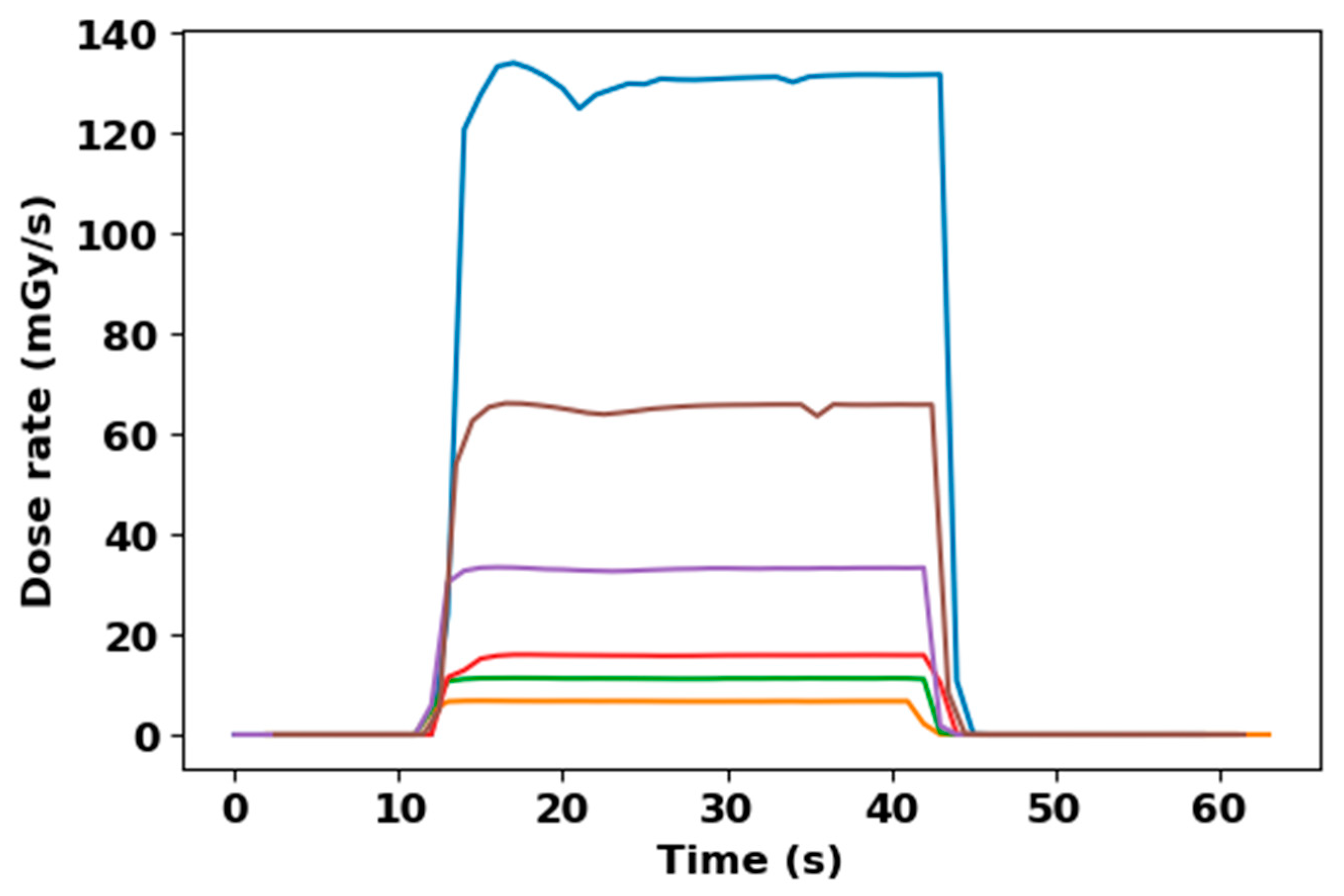
3.1. Quasi-Continuous Mode Characterization

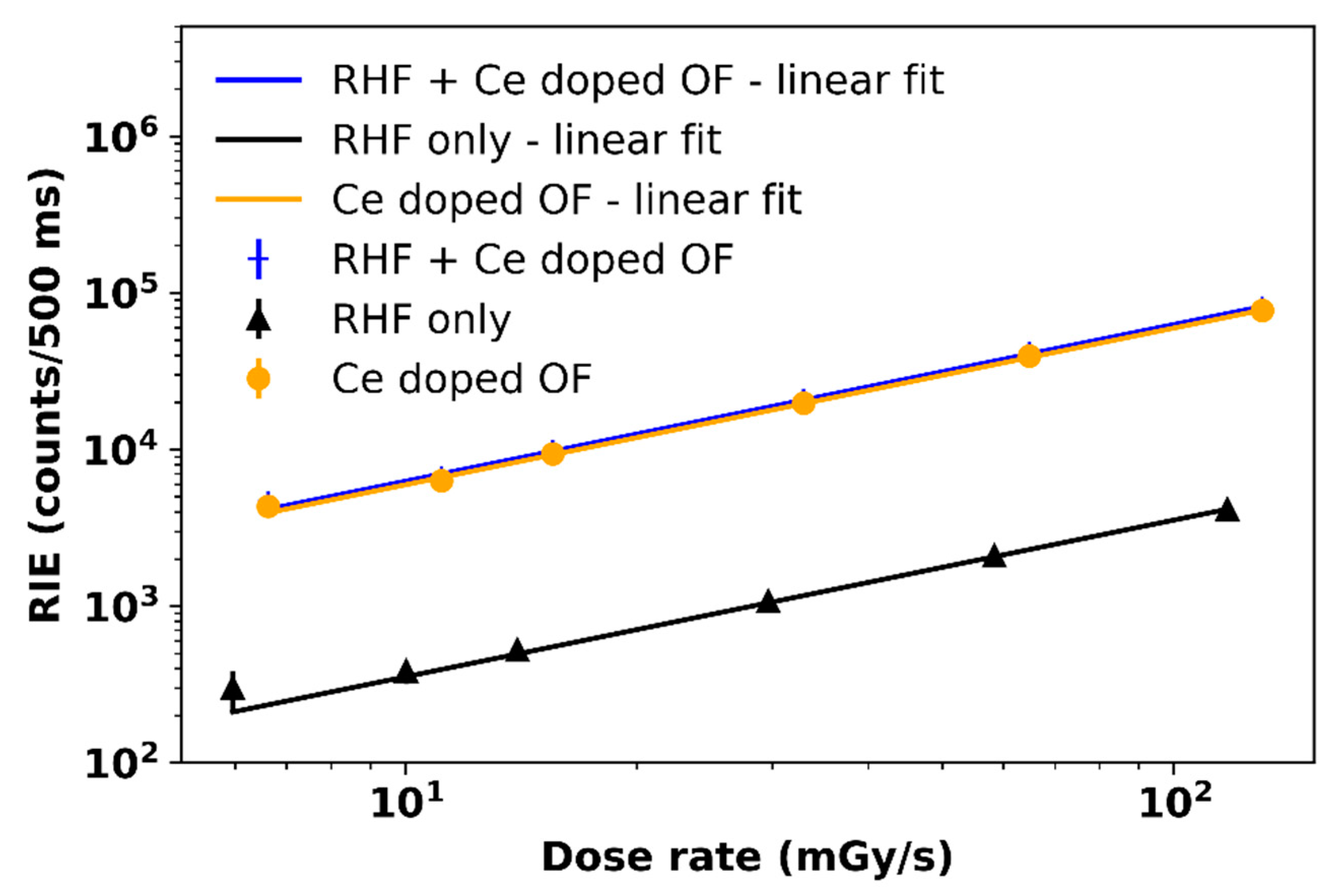
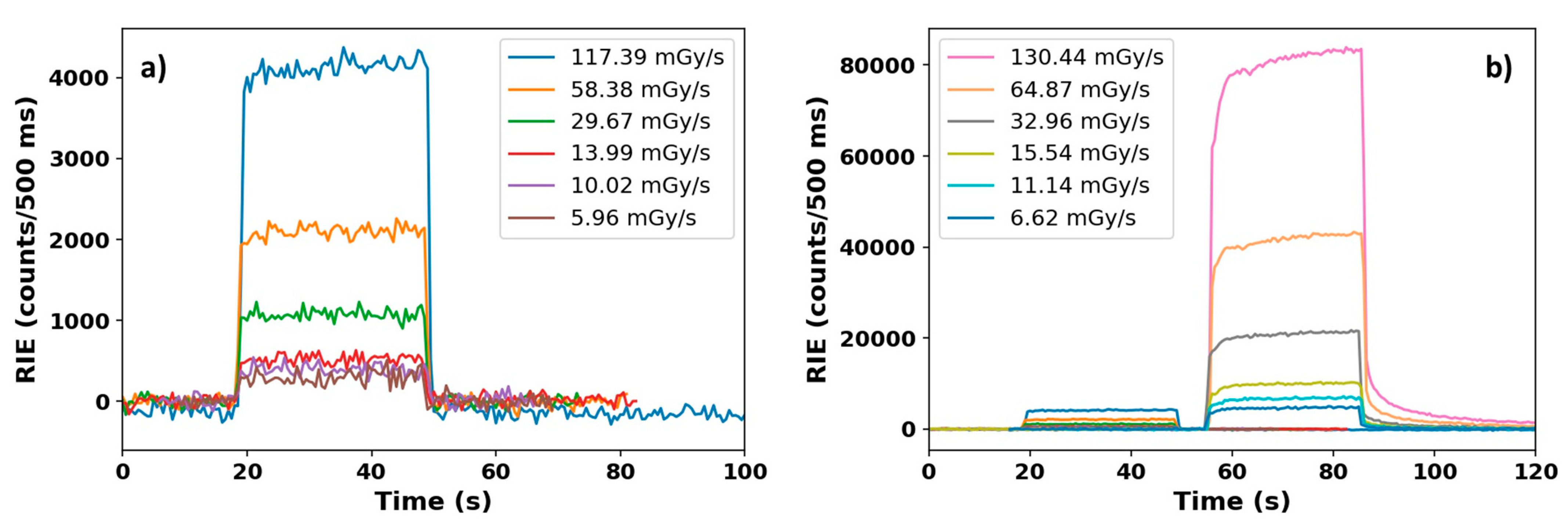
3.1.1. RIE versus Dose Rate Experiments

Four irradiations were performed at different trigger frequencies. At the maximal frequency available in quasi-continuous mode, i.e., 195 Hz, and the maximum RF frequency giving a pulse duration of 4.8 µs, the accelerator delivered a dose rate of 130.44 mGy(SiO2)/s at 1 m from the target. Irradiation runs that were 30 s long were successively performed at different frequencies, 98 Hz, 49 Hz and 25 Hz, corresponding to dose rate values of 64.87, 32.96 and 15.54 mGy(SiO2)/s, respectively. Additionally, as mentioned before, there was the possibility of changing the RF frequency to decrease the pulse duration, with the delivered dose rate reaching 11.14 and 6.62 mGy(SiO2)/s. For these tests, the PMT time gate was kept at 500 ms. The results are shown in Figure 7a for the sole RHF and in Figure 7b for the coupled RHF + Ce-doped fiber (entire sensor). Moreover, by considering the different locations of the RHF and the Ce-fiber within the beam, the dose rates used for the sole RHF were considered at 90% of the total dose rate (see Figure 7a). However, when the results were compared, the RHF intensity produced during the irradiation of the complete sample was evaluated at the same dose rates (Figure 7b).
At ORIATRON, the RIE in the optical fibers can originate from both Cerenkov and RIL. From a recent study [49], RIL was already measured on 10 cm of the F-clad radiation-hardened OF with 40 keV X-ray at dose rate of 0.1 Gy(SiO2)/s with a level of a few hundred counts/s in the same PMT device with a shorter radiation-hardened transport fiber. In our case, the total length of RHF irradiated with dose rates from 10−3 to 0.1 Gy(SiO2)/s was about 25 cm from the source, with the length going out from the irradiation spot. As illustrated by Figure 7a, the luminescence of the sole RHF was much higher than the one measured under 40 keV X-rays. This larger emission is explained by the Cerenkov contribution that occurs for X-rays with energy higher than a few hundred keV [50] (>0.2 MeV for glass refractive index between 1.46 and 1.52 [51]) due to the Compton scattering of secondary electrons. We then suggest that the light emitted in the sole RHF at ORIATRON is mainly composed of Cerenkov radiation. From the results of the RIE measured with the coupled fibers presented in the Figure 7b, and due to coupling, the contribution of the Cerenkov radiation and the low RIL intensity of the transport fiber contributed to less than 5% of the Ce sample RIE. This can be also highlighted by studying the luminescence decay time at different dose rates. By normalizing the RIE signal (with the average of the RIE plateau), the relative RIE decay can be constructed as shown in Figure 8a for the sole RHF and by the Figure 8b for the coupled RHF and Ce-doped sample.
The RIE of the RHF decreased by 90% 1–2 s after the irradiation (Figure 8a). This decay also corresponded to the accelerator fall down measured by the ionizing chamber (Figure 6). Because of the coupling between RHF and Ce-doped sample, the decay of the RHF RIE in the coupled sample RIE decay should be identical in terms of delay. The rest of the decay should only be composed of the luminescence related to the Ce ions. Meyer et al. in [49] showed its continuous X-ray RIL decay is over 50 s for dose rates between 0.1 and 15 Gy(SiO2)/s. Regarding the measured decay time, the very long decay cannot be related to PL processes. However, Veronese et al. [52] reported phosphorescence emission for Ce-doped optical fiber with decay time exceeding a few seconds, compatible with the RIE decay observed here.

3.1.2. Correlation between RIE Plateau and Dose Rates

From Figure 7, we can extract a first correlation between the RIE of both samples versus the facility dose rates. This was constructed by taking an average of the RIE plateau (corresponding to the RIE between t = 30 s and t = 48 s in Figure 7a for the sole RHF and between t = 65 s and t = 83 s in Figure 7b for the coupled sample) at each tested dose rate. To build a correlation, a linear fit, based on Equation (2), was applied to the data and is represented by the black full line in Figure 9.
R I E ( d D d t ) = A d D d t
where the slope A is a phenomenological parameter without real physical meaning.
In the quasi-continuous mode, the accelerator started by a rise ramp to reach its nominal flux with a delay as long as 10 s, illustrated by the stabilization of the blue line in Figure 6 between t = 11 s and t = 21 s. This rise time is mainly due to the delay to stabilize the plasma producing the RF electric field in the magnetron. During this transition window, X-rays were produced with an increasing dose rate, which was fully characterized by the rise in the RIE for each selected dose rate. After this delay, the flux became more stable and the RIE intensity reached a plateau related to the flux level and thus the dose rate. We could also observe a slight RIE increase in the Ce-doped fiber (Figure 7b) during the stabilized flux production for each dose rate, used mainly after t = 61 s. This is known under the name of Bright Burn Effect [53]. This mechanism is described by the detrapping of electrons staying at energy levels with higher activation energy than the radioluminescent trap levels. This is known in the semiconductor domain to be associated with the concentration of impurities present in silicon composition because of their contribution in charge transport in the semiconductor. In the literature, the carrier recombination processes have been deeply studied since the 1950s from the Schockley–Read–Hall process [54,55]. This mechanism suggests the presence of recombination mechanisms combining radiative and non-radiative decays activated by the energy transfer carried out by radiation knocking, such as Compton scattering and electronic or nuclear recoil. This is proposing to activate radiative and non-radiative recombinations from atomic structure, which are initially passive. They reach the excitation states by the energy deposited in the atomic structure, which generates charge [56]. The recombination is then initiated by the energy stimulation. The production of electron recoils in the silica matrix can generate deep trap recombination, detected for its radiative component by the optical fiber-based sensor. Presented another way, the difference in plateau evolution between the RHF RIE and the coupled samples RIE leads to combine the increase in the RIE level after t = 71 s in Figure 7b, with the production of cerium defects initially passive in the silica matrix. Further studies should be performed to identify the contributors responsible for the increase, which is actually affecting the RIE not higher than 5%. Successive irradiations at the same dose rates several times would allow better understanding of the dose dependence of this effect.
For the coupled RHF + Ce-doped OF, this is illustrated in Figure 9 by the blue crosses, which are combined with the RHF results in black dots. The RIE (counts/500 ms) is fitted with a linear function versus dose rate in the entire range with Equation (2) for both samples. By subtracting the signals from the two fibers, the RIE from the sole Ce-doped fiber can be calculated and is given in Figure 9. Table 1 summarizes the fit parameters used for the data for each fiber.

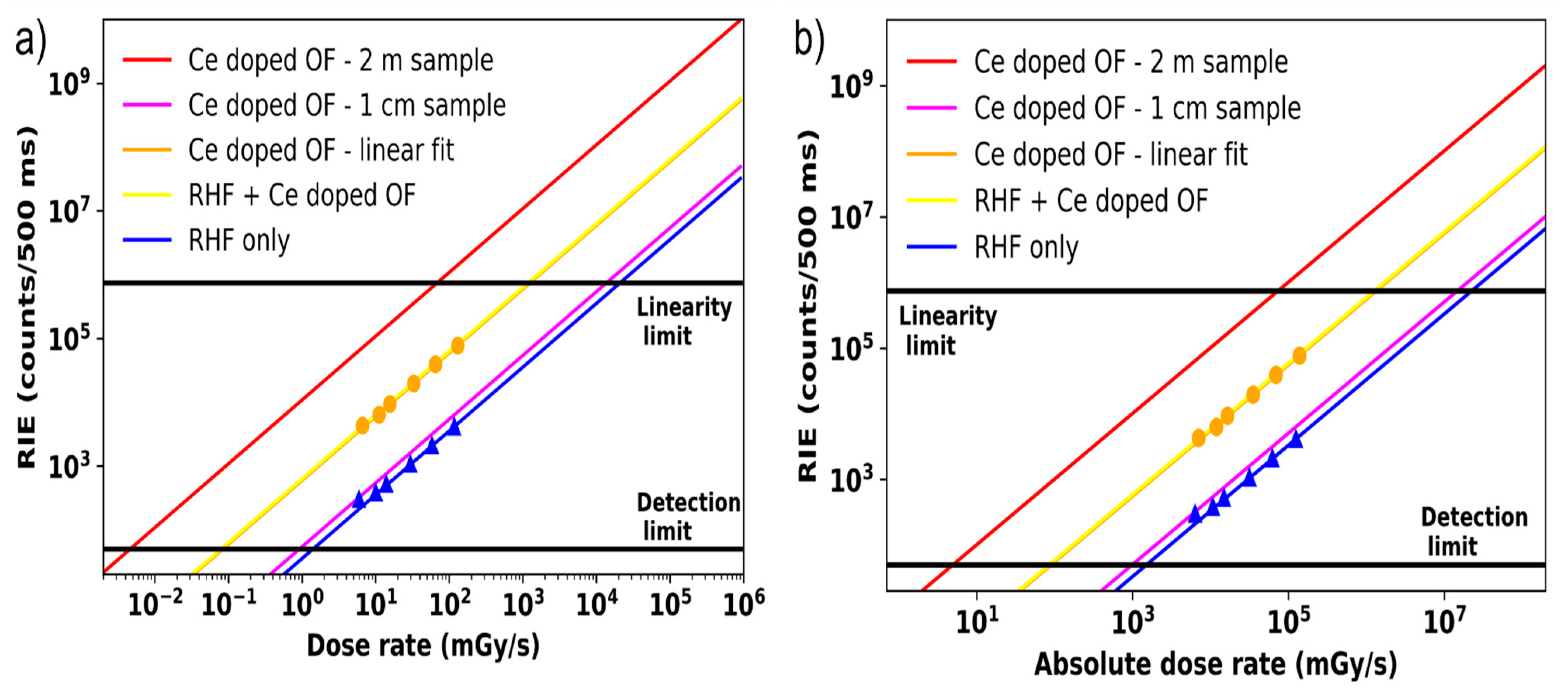
3.1.3. Extension of the Dose Rate Range

In Figure 9, the dose rate ranges from 4 to 133 mGy(SiO2)/s. The experiments carried out during the previous irradiations allowed us to consider an extension of the dose rates range: our PMT detectors were far from their saturation level, while remaining in their linear operating regimes. Supposing the RIE linearity can be achieved within an extended dose rate range, this sample of optical fiber of a few centimeters could be able, by extrapolation, to measure dose rates in a range between 10−1 and 1 Gy(SiO2)/s. This is illustrated by the red line in Figure 10a fitting the averaged RIE produced by the 11 cm sample of Ce-doped OF coupled to the RHF.
Accordingly, a limit for the highest dose rate is defined when the RHF is the sole radiation sensor present, shown as the purple line in Figure 10a. With such detection setup and this sensor design, the upper limit of the range of dose rates would be between a 10−1 mGy(SiO2)/s and 10 Gy(SiO2)/s for RIE integrated on 500 ms.
On the other hand, there is also the possibility of increasing the sensitive part to detect much lower dose rates. For instance, represented by the red line in Figure 10a, with a 2 m Ce-doped optical fiber as sensor, the dose rate range could in principle be shifted towards lower values, from 5 × 10⁻³ to almost 102 mGy(SiO2)/s. However, adding length to the sample could reduce the lifetime of the radiation sensor, as it would be more quickly affected by the RIA. However, if the dose rate range, selected to use 2 m of optical fiber is kept low enough, the cumulative dose per irradiation run would be small enough to ensure the sensor performance for a long time. Another method for increasing the sensitivity of the optical fiber-based sensor would be an increase in the radius of the sensitive volume. In our case, the sensitive volume was concentrated into the 50 µm fiber core and could be increased in order to transform the optical fiber into bigger rods, which are much more sensitive [18]. By increasing the doped-core radius, the sensitivity would be increased as the square of the radius: doubling the core radius increases the sensor sensitivity by a factor of 4.
Working with pulsed X-ray beam, another way of considering the dose rate sensitivity is to consider the dose rate normalized to the pulse duration, also called absolute dose rate [57], as found in FLASH therapy context, for example. With the highest dose rate reached at ORIATRON facility using an X-ray beam with a production rate of 195 Hz, a pulse duration of 4.8 µs and at 1 m from the electron conversion target, the dose rate reported was 130 mGy(SiO2)/s. During a single pulse, this gave a dose rate of 138 Gy(SiO2)/s. Using the same method for the full dose rate range, which can be detected by the used optical fiber samples, the absolute dose rate characterizable is reported in the Figure 10b and took the range from 102 to almost 107 mGy(SiO2)/s with the current setup using samples of 1 cm to 11 cm of length.
As explained previously, this X-ray beam is composed of multiple pulses cadenced at a tunable frequency chosen by the user. The dose rate is adjusted by changing the pulse production rate, which defines the temporal interval between two successive pulses. Thanks to the fast decay time of the Ce3+ ions luminescence, the temporal pulsed substructure of the ORIATRON beam can be identified. This provides the possibility of monitoring individual X-ray pulses over time.

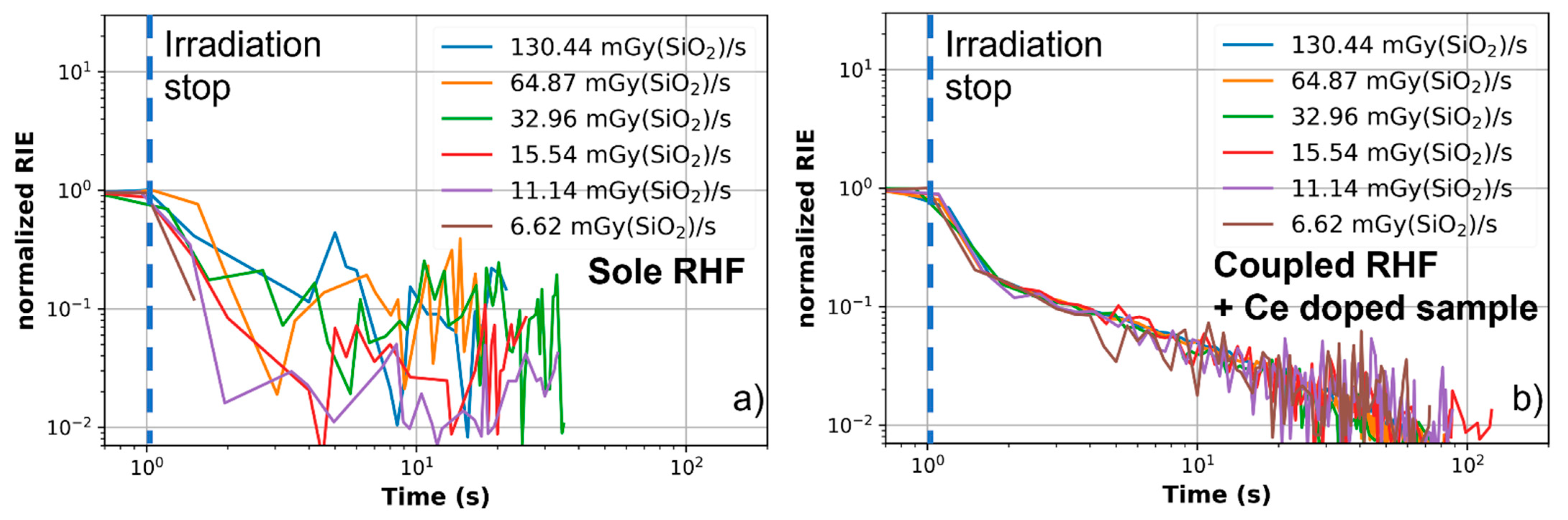
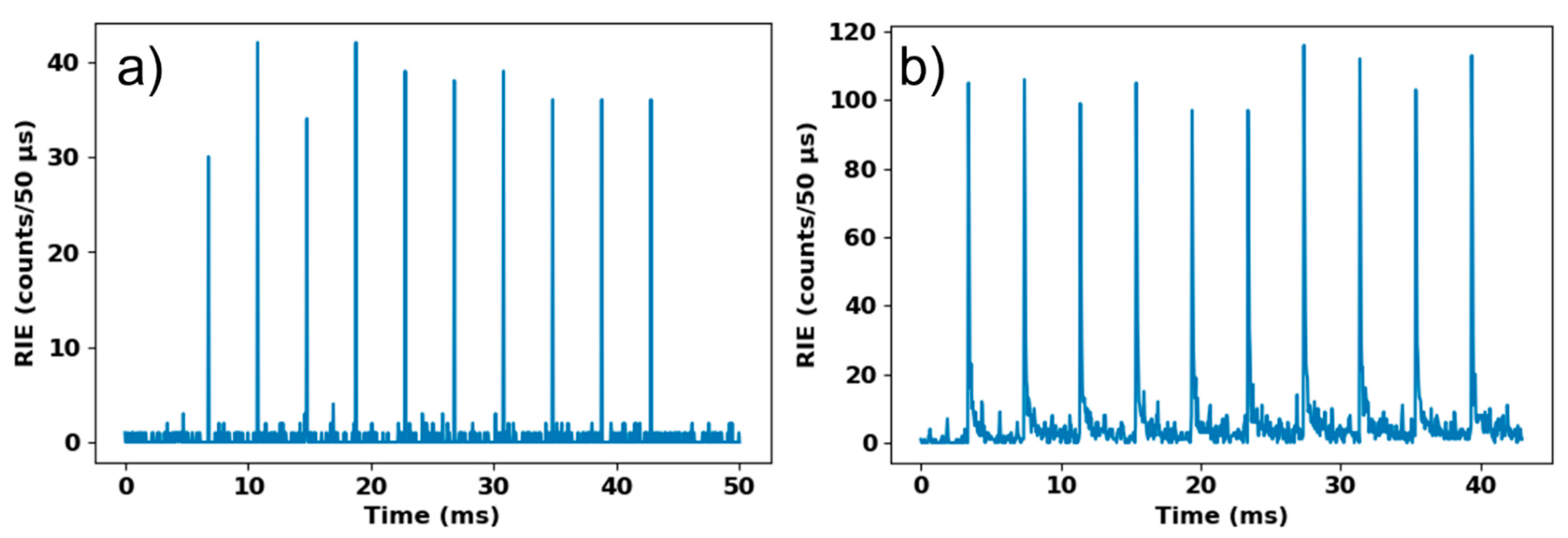
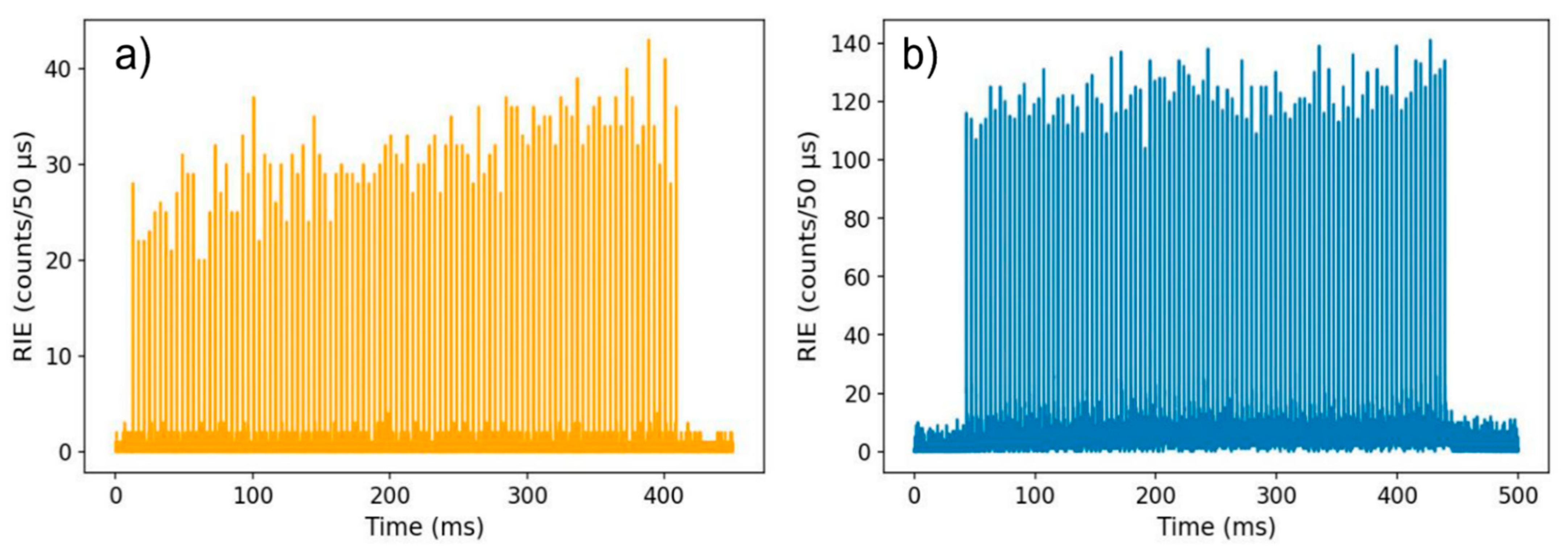
3.2. Pulse Separation

Each set of pulses was recorded as explained above, with the fiber irradiated at one meter from the target. The characterization of the pulsed mode consisted in matching the achieved number of pulses and the number of RIE peaks detected by the PMT. Typical results are illustrated in Figure 11a (RHF-only) and Figure 11b (Ce-doped+RHF).
As an example, the signal obtained with the RHF fiber could be separated in two different steps. The first one was the electronic noise of the PMT. The second part contained the peaks corresponding to the interaction X-rays with the fiber. For this RHF fiber, these peaks exhibited small amplitude, since there was only the small Cerenkov emission. For the Ce-doped fiber signal, a longer decay between peaks was observed and the signal also had a higher intensity, which made the radiation pulse detection easier with a better signal dynamic. One could thus clearly see an additional light coming from the Ce-RIL, which added new photons to the two previously described processes. Particularly, it is interesting to note that the decay of the RIE between each pulse could be perfectly observed. To extract the signal of interest corresponding to the pulse detection, we had to consider that the Cerenkov emission was perfectly timed with the X-ray pulse train. Moreover, Ce luminescence added its contribution from the first X-ray/fiber interaction up to the decay of the cerium states (~84 ns [44]). Additionally, through radiative recombination, photons were still emitted during a short delay after the end of the pulse. As described above, the pulse width was 4.8 µs, but the PMT time gate could not be shorter than 50 µs, so the most important part of the signal that integrated most of radiation-induced emission was the top of the peak, signature of the X-rays/fiber interaction. For all pulse sets, the number of RIE peaks measured was counted by taking only the peak maximum and comparing with the number of triggers sent to produce the X-ray pulses.
The obtained RIE intensity was a mean effect of the interaction between the X-ray burst and the optical fiber. However, this mean signature was sufficiently separated from the noise background to follow the pulse series at the highest available frequency, with the RHF as well as with the Ce-doped fiber coupled to the RHF fiber. These optical fibers could track the X-ray pulses delivered by this radiation source without any pile-up. It could be used to monitor in real-time a pulsed X-ray source at a larger frequency rate than ORIATRON, up to 500 Hz typically. At this point, two sensor architectures can be designed depending on the targeted application. With the sole rad-hard fiber, the monitored X-ray photon flux can be increased thanks to its lower RIE level and fast decay time. If the application requires higher sensitivity, the Ce-doped optical fiber should be preferred thanks to its higher emission level.
The analysis of the RIE measured for irradiations with 100 X-ray pulses was performed to study statistically the RIE dispersion. This is illustrated in Figure 12a for the RHF alone and in Figure 12b for the full detector (coupled RHF and Ce-doped OF). According to these measurements, the RIE varied by ~6.3% for the complete detection samples and by ~15% for the RHF only using a non-stabilized regime of the accelerator because of the very short time of irradiation. With this kind of radiation pulse production, the interaction signature seemed governed by the dose deposited by each single pulse over its duration. The optical fiber response could exceed the pulse duration, considering the recombination mechanism appearing between the end of the pulse interaction and the PMT time gate window closing. The main source of the RIE integrated into each measured single peak was thus the deposited dose. By integrating the RIE peaks within 500 ms, the relation between these measurements and those performed in the quasi-continuous mode was calculated. The produced RIE reached 6 × 10⁴ counts/500 ms at a dose rate of 167.2 mGy(SiO2)/s (250 Hz, pulse duration 4.8 µs), which was consistent with the plateau measured in continuous mode for the coupled samples, and 4000 counts/500 ms were measured for the sole RHF. These results confirm that RIE obtained for each fiber in quasi-continuous mode resulted from the integral over the time of the contribution of the different pulses.

4. Conclusions

In this study, we demonstrated the possibility of exploiting the radioluminescence of small-size (50 µm core diameter) Ce-doped optical fibers as a figure of merit for monitoring X-ray dose rates from mGy(SiO2)/s to Gy/s. Irradiations with automatic production of X-ray pulses were also performed, leading to a dose rate range between 6.5 and 130 mGy(SiO2)/s. For each studied dose rate, the RIE was quite stable and its variations remained inferior to 5%. This was demonstrated on a wide dose rate range, which made it possible to build a linear correlation between the emitted signal and the photon flux for our probes consisting in 11 cm of Ce-doped fiber spliced to a radiation-hardened transport fiber. We also characterized the RIE contribution of the radiation-resistant transport line that was mainly related to Cerenkov emission. Our results demonstrate that it is possible to monitor X-ray beams with the 2 m long Ce-doped probe for absolute dose rates ranging from 102 to 107 mGy(SiO2)/s for pulse duration of 4.8 µs. Moreover, thanks to the fast decay of the Ce radioluminescence, this optical fiber was able to track every X-ray pulse in a long set triggered at 250 Hz. The system should thus be able to operate up to 500 Hz. Modulating the optical fiber sensitive volume allows selecting the dose rate range over more than five decades which corresponds to usual X-ray sources as well as more specific irradiation facilities oriented to FLASH therapy. Furthermore, considering the high dose rate that can be characterized by this kind of optical fiber, the monitoring of sources such as Marx generator-based X-ray sources or high-energy Compton scattering sources seems achievable. This will be investigated during upcoming test campaigns to further explore the sensor potential. In addition, studies about the sensor lifetime, based on measured RIA, have to be performed to guarantee that its performance is maintained at larger cumulated doses. Finally, the conversion target could be removed to investigate new irradiation fields using electron bunches instead of X-rays.

Author Contributions

Resources, H.E.H., A.B., G.B., A.C., B.C. and M.B.; conceptualization, J.V., A.M., S.G. and P.P.; methodology, A.M., S.G. and P.P.; validation, A.M., S.G. and P.P.; formal analysis, J.V.; investigation, J.V., A.M., M.G. and S.G.; writing—original draft preparation, J.V.; writing—review and editing, J.V., A.M., H.E.H., A.B., G.B., A.C., B.C., Y.O., M.G., M.B., S.G. and P.P.; supervision, A.M., H.E.H., A.B., G.B., A.C., B.C., Y.O., M.G., M.B., S.G. and P.P.; funding acquisition, S.G. and P.P. All authors have read and agreed to the published version of the manuscript.

Funding

This research was funded by the LABEX CEMPI (ANR-11-LABX-0007) and the Equipex Flux (ANR-11-EQPX-0017), as well as by the Ministry of Higher Education and Research, Hauts de France Council and European Regional Development Fund (ERDF) through the Contrat de Projets Etat-Region (CPER Photonics for Society P4S).

Institutional Review Board Statement

Not applicable.

Informed Consent Statement

Not applicable.

Data Availability Statement

The data supporting the findings of this study are available from the corresponding authors upon reasonable request.

Acknowledgments

H.E.H., G.B., A.C., B.C. and M.B. would like to thank FiberTech Lille platform for its technical support.

Conflicts of Interest

The authors declare no conflict of interest.

References

  1. Schmidt, B. The High-Luminosity upgrade of the LHC: Physics and Technology Challenges for the Accelerator and the Experiments, XIII International Workshop on Hadron Physics. J. Phys. Conf. Ser. 2016, 706, 022002. [Google Scholar] [CrossRef] [Green Version]
  2. Duzellier, S. Radiation effects on electronic devices in space. Aerosp. Sci. Technol. 2005, 9, 93–99. [Google Scholar] [CrossRef]
  3. Dias, H.; Lefesvre, I.; Le Coeur, D. Radiation effects on spatial dark current fluctuations in charge coupled devices (CCD) image sensors. In Proceedings of the Space Optics 1994: Space Instrumentation and Spacecraft Optics. International Society for Optics and Photonics, Garmisch, Germany, 30 September 1994; Volume 2210, pp. 466–473. [Google Scholar]
  4. Hughes, J.R.; Parsons, J.L. FLASH radiotherapy: Current knowledge and future insights using proton-beam therapy. Int. J. Mol. Sci. 2020, 21, 6492. [Google Scholar] [CrossRef]
  5. Kumar, A.S.; Sharma, S.D.; Ravindran, B.P. Characteristics of mobile MOSFET dosimetry system for megavoltage photon beams. J. Med. Phys. 2014, 39, 142–149. [Google Scholar]
  6. Beaulieu, L.; Goulet, M.; Archambault, L.; Beddar, S. Current status of scintillation dosimetry for megavoltage beams. J. Phys. Conf. Ser. 2013, 444, 012013. [Google Scholar] [CrossRef]
  7. Butson, M.J.; Yu, P.K.N.; Cheung, T.; Metcalfe, P. Radiochromic film for medical radiation dosimetry. Mat. Sci. Eng. R Rep. 2003, 41, 61–120. [Google Scholar] [CrossRef]
  8. Medin, J.; Andreo, P.; Grusell, E.; Mattsson, O.; Montelius, A.; Roos, M. Ionization chamber dosimetry of proton beams using cylindrical and plane parallel chambers. Nw versus Nk ion chamber calibrations. Phys. Med. Biol. 1995, 40, 1161–1176. [Google Scholar] [CrossRef]
  9. Kry, S.F.; Price, M.; Followill, D.; Mourtada, F.; Salehpour, M. The use of LiF (TLF-100) as an out-of-field dosimeter. J. Appl. Clin. Med. Phys. 2007, 8, 169–175. [Google Scholar] [CrossRef]
  10. Bilski, P.; Budzanowski, M.; Olko, P.; Mandowska, E. LiF: Mg, Ti (MTT) TL detectors optimized for high-LET radiation dosimetry. Radiat. Meas. 2004, 38, 427–430. [Google Scholar] [CrossRef]
  11. Wilson, J.D.; Hammond, E.M.; Higgins, G.S.; Petersson, K. Ultra-high dose rate (FLASH) radiotherapy: Silver bullet or fool’s gold. Front. Oncol. 2019, 9, 1563. [Google Scholar] [CrossRef] [PubMed] [Green Version]
  12. Girard, S.; Kuhnhenn, J.; Gusarov, A.; Brichard, B.; Van Uffelen, M.; Ouerdane, Y.; Boukenter, A.; Marcandella, C. Radiation effects on silica-based optical fibers: Recent advances and future challenges. IEEE TNS 2013, 60, 2015–2036. [Google Scholar] [CrossRef]
  13. Remy, L.; Cheymol, G.; Gusarov, A.; Morana, A.; Marin, E.; Girard, S. Compaction in optical fibers and fibre Bragg gratings under nuclear reactor high neutron and gamma fluence. IEEE TNS 2013, 63, 2317–2322. [Google Scholar]
  14. Girard, S.; Alessi, A.; Richard, N.; Martin-Samos, L.; De Michelea, V.; Giacomazzi, L.; Agnello, S.; Di Francesca, D.; Morana, A.; Winkler, B.; et al. Overview of radiation induced point defects in silica-based optical fibers. Rev. Phys. 2019, 4, 100032. [Google Scholar] [CrossRef]
  15. Di Francesca, D.; Li Vecchi, G.; Girard, S.; Alessi, A.; Reghioua, I.; Boukenter, A.; Ouerdane, Y.; Kadi, Y.; Brugger, M. Radiation-induced attenuation in single-mode phosphosilicate optical fibers for radiation detection. IEEE TNS 2017, 65, 126–131. [Google Scholar] [CrossRef]
  16. Olusoji, O.J.; Penner, C.; Bélanger-Champagne, C.; Kam, W.; Martyn, M.; Woulfe, P.; Hoehr, C.; O’Keeffe, S. Dosimetric application of phosphorus doped fibre for X-ray and proton therapy. Sensors 2021, 21, 5157. [Google Scholar] [CrossRef]
  17. Girard, S.; Baggio, J.; Bisutti, J. 14-MeV Neutron, γ-Ray and Pulsed X-ray Radiation-Induced Effects on Multimode Silica-Based Optical Fibers. IEEE TNS 2006, 53, 3750–3757. [Google Scholar] [CrossRef]
  18. Hoehr, C.; Morana, A.; Duhamel, O.; Capoen, B.; Trinczek, M.; Paillet, P.; Duzenli, C.; Bouazaoui, M.; Bouwmans, G.; Cassez, A.; et al. Novel Gd3+-doped silica-based optical fiber material for dosimetry in proton therapy. Sci. Rep. 2019, 9, 2045–2322. [Google Scholar] [CrossRef]
  19. De Michele, V.; Marcandella, C.; Vidalot, J.; Paillet, P.; Morana, A.; Cannas, M.; Boukenter, A.; Marin, E.; Ouerdane, Y.; Girard, S. Origins of radiation-induced attenuation in pure-silica-core and Ge-doped optical fibers under pulsed X-ray irradiation. J. Appl. Phys. 2020, 128, 103101. [Google Scholar] [CrossRef]
  20. Girard, S.; Ouerdane, Y.; Marcandella, C.; Boukenter, A.; Quenard, S.; Authier, N. Feasability of radiation dosimetry with phosphorus-doped optical fibers in the ultraviolet and visible domain. J. Non-Cryst. Solids 2011, 357, 1871–1874. [Google Scholar] [CrossRef]
  21. Di Francesca, D.; Li Vecchi, G.; Girard, S.; Morana, A.; Reghioua, I.; Alessi, A.; Hoehr, C.; Robin, T.; Kadi, Y.; Brugger, M. Qualification and calibration of single-mode phosphosilicate optical fiber for dosimetry at CERN. J. Light. Technol. 2019, 37, 4643–4649. [Google Scholar] [CrossRef]
  22. Campanella, C.; De Michele, V.; Morana, A.; Guttilla, A.; Mady, F.; Benabdesselam, M.; Marin, E.; Boukenter, A.; Ouerdane, Y.; Girard, S. Temperature Dependence of Radiation Induced Attenuation of Aluminosilicate Optical Fiber. IEEE TNS, 2021; in press. [Google Scholar]
  23. Di Francesca, D.; Infantino, A.; Li Vecchi, G.; Girard, S.; Alessi, A.; Kadi, Y.; Brugger, M. Dosimetry mapping of mixed field radiation environment through combined distributed optical fiber sensing and FLUKA simulation. IEEE TNS 2018, 66, 299–305. [Google Scholar] [CrossRef]
  24. Li Vecchi, G.; Di Francesca, D.; Ferraro, R.; Danzeca, S.; Stein, O.; Kadi, Y.; Brugger, M. Distributed Optical fiber Radiation Sensing at CERN. In Proceedings of the 9th International Particle Accelerator Conference, IPAC, Vancouver, BC, Canada, 29 April–4 May 2018. [Google Scholar]
  25. Dianov, E.M.; Golant, K.M.; Khrapko, R.R.; Mashinsky, V.M.; Neustruev, V.B.; Guryanov, A.N.; Gusovsky, D.D.; Miroshnichenko, S.I.; Sazhin, O.D. Radiation resistance of optical fibres with fluorine-doped silica cladding. In Proceedings of the Optical Fibre Sensing and Systems in Nuclear Environments, Mol, Belgium, 30 December 1994; Volume 2425, pp. 58–62. [Google Scholar]
  26. Girard, S.; Vivona, M.; Laurent, A.; Cadier, B.; Marcandella, C.; Robin, T.; Pinsard, E.; Boukenter, A.; Ouerdane, Y. Radiation hardening techniques for Er/Yb doped optical fibers and amplifiers for space application. Opt. Express. 2021, 20, 8457–8465. [Google Scholar] [CrossRef] [PubMed]
  27. Vivona, M.; Girard, S.; Marcandella, C.; Pinsard, E.; Laurent, A.; Robin, T.; Cadier, B.; Cannas, M.; Boukenter, A.; Ouerdane, Y. Radiation hardening of rare-earth doped fiber amplifiers. In Proceedings of the International Conference on Space Optics 2012, Ajaccio, Corsica, France, 20 November 2017; Volume 10564, p. 105641. [Google Scholar]
  28. Cerenkov, P.A. Visible Radiation Produced by Electrons Moving in a Medium with Velocities Exceeding that of Light. Phys. Rev. 1937, 52, 378–379. [Google Scholar] [CrossRef]
  29. Tamm, I.E. General characteristics of vavilov-cherenkov radiation. Science 1960, 131, 206–210. [Google Scholar] [CrossRef]
  30. Ciarrocchi, E.; Belcari, N. Cerenkov luminescence imaging: Physics principles and potential applications in biomedical sciences. EJNMMI Phys. 2017, 4, 1–31. [Google Scholar] [CrossRef] [Green Version]
  31. Jackson, J.D. Classical Electrodynamics, 3rd ed.; John Wiley & Sons: Hoboken, NJ, USA, 1998. [Google Scholar]
  32. Lambert, J.; Yin, Y.; McKenzie, D.R.; Law, S.; Suchowerska, N. Cerenkov light spectrum in an optical fiber exposed to a photon or electron radiation therapy beam. Appl. Opt. 2009, 48, 3362–3367. [Google Scholar] [CrossRef]
  33. Shinde, K.N.; Dhoble, S.J.; Swart, H.C.; Park, K. Basic mechanisms of photoluminescence. In Phosphate Phosphors for Solid-State Lightning; Springer Series in Materials Science: Berlin/Heidelberg, 2012; Volume 174. [Google Scholar]
  34. Chen, R.; Pagonis, V. Advances in Physics and Applications of Optically and Thermally Stimulated Luminescence; World Scientific: Signapore, 2019. [Google Scholar]
  35. Al Helou, N. Study of Glasses for Fibered Dosimetry of Ionizing Radiation. PhD Thesis, PhLAM Laboratory, University of Lille, Lille, France, 2018. [Google Scholar]
  36. Veronese, I.; Cantone, M.C.; Chiodini, N.; Coraye, A.; Fasoli, M.; Lomax, A.; Mones, E.; Moretti, F.; Vedda, A. Feasability study for the use of the cerium-doped silica fibres in proton therapy. Radiat. Meas. 2010, 45, 635–639. [Google Scholar] [CrossRef]
  37. Mones, E.; Veronese, I.; Moretti, F.; Fasoli, M.; Loi, G.; Negri, E.; Brambilla, M.; Chiodini, N.; Brambilla, G.; Vedda, A. Feasibility study for the use of Ce3+ -doped optical fibres in radiotherapy. NIM A 2006, 562, 449–455. [Google Scholar] [CrossRef]
  38. Aubert, D.; Assaillit, G.; Auriel, G.; Delbos, C.; Garrigues, A.; de Gaufridy, F.; Labarbe, L.; Plouhinec, D.; Queiros, A.; Ribeiro, P.; et al. A 6 MeV electron linac facility for multipurpose radiation testing. In Proceedings of the 16th European Conference on Radiation and Its Effects on Components and Systems RADECS, Bremen, Germany, 19–23 September 2016; pp. 1–3. [Google Scholar]
  39. Lambert, D.; Gaillardin, M.; Raine, M.; Paillet, P.; Duhamel, O.; Marcandella, C.; Martinez, M.; Rostand, N.; Lagutère, T.; Aubert, D.; et al. TID effects induced by ARACOR, 60Co and ORIATRON photon sources in MOS devices: Impact of geometry and materials. IEEE TNS 2021, 68, 991–1001. [Google Scholar] [CrossRef]
  40. Available online: https://www.ptwdosimetry.com/products/farmer-ionization-chamber-30013-waterproof/?L=0 (accessed on 20 October 2021).
  41. Agostinelli, S.; Allison, J.; Amako, K.; Apostolakis, J.; Araujo, H.; Arce, P.; Asai, M.; Axen, D.; Banerjee, S.; Barrand, G.; et al. GEANT4–simulation toolkit. NIM A 2003, 506, 250–303. [Google Scholar] [CrossRef] [Green Version]
  42. Allison, J.; Amako, K.; Apostolakis, J.; Araujo, H.; Arce Dubois, P.; Asai, M.; Barrand, G.; Capra, R.; Chauvie, S.; Chytracek, R.; et al. Geant4 developments and applications. IEEE TNS 2006, 53, 270–278. [Google Scholar] [CrossRef] [Green Version]
  43. Vedda, A.; Chiodini, N.; Di Martino, D.; Fasoli, M.; Keffer, S.; Lauria, A.; Martini, M.; Moretti, F.; Spinolo, G. Ce3+ -doped fibers for remote radiation dosimetry. Appl. Phys. Lett. 2004, 85, 6356–6358. [Google Scholar] [CrossRef]
  44. Bahout, J.; Ouerdane, Y.; El Hamzaoui, H.; Bouwmans, G.; Bouazaoui, M.; Cassez, A.; Baudelle, K.; Habert, R.; Morana, A.; Boukenter, A.; et al. Remote measurements of X-rays dose rate using a cerium-doped air-clad optical fiber. IEEE Trans. Nucl. Sci. 2020, 67, 1658–1662. [Google Scholar] [CrossRef]
  45. Ishii, Y.; Arai, K.; Namikawa, H.; Tanaka, M.; Negishi, A.; Handa, T. Preparation of cerium-activated silica glasses: Phosphorus and aluminium codoping effects on absorption and fluorescence properties. J. Am. Ceram. Soc. 1987, 70, 72–77. [Google Scholar] [CrossRef]
  46. El Hamzaoui, H.; Capoen, B.; Al Helou, N.; Bouwmans, G.; Ouerdane, Y.; Boukenter, A.; Girard, S.; Marcandella, C.; Duhamel, O.; Chadeyron, G. Cerium-activated sol–gel silica glasses for radiation dosimetry in harsh environment. Mater. Res. Express 2016, 3, 046201. [Google Scholar] [CrossRef]
  47. Available online: https://www.hamamatsu.com/resources/pdf/etd/H7421_TPMO1099E.pdf (accessed on 20 October 2021).
  48. Kerboub, N.; Di Francesca, D.; Girard, S.; Morana, A.; El Hamzaoui, H.; Ouerdane, Y.; Bouwmans, G.; Habert, R.; Boukenter, A.; Capoen, B.; et al. Temperature effect on the radioluminescence of Cu, Ce and CuCe doped silica-based fiber materials. IEEE TNS 2021, 68, 1782–1787. [Google Scholar] [CrossRef]
  49. Meyer, A.; Morana, A.; El Hamzaoui, H.; Capoen, B.; Bouwmans, G.; Bouazaoui, M.; Girard, S.; Marin, E.; Ouerdane, Y.; Boukenter, A. X-ray Radioluminescence in Diversely Doped Multimode Silica-based Optical Fibers. In Proceedings of the Conference RADECS 2021-Radiation and Its Effects on Components and Systems, IEEE TNS, Vienna, Austria, 13–17 September 2021. [Google Scholar]
  50. Krajewska, K.; Cajiao Vélez, F.; Kamiński, J.Z. Generalized Klein-Nishina Formula. Phys. Rev. A 2015, 96, 2106. [Google Scholar] [CrossRef] [Green Version]
  51. Moore, A.S.; Schlossberg, D.J.; Hartouni, E.P.; Sayre, D.; Eckart, M.J.; Hatarik, R.; Barbosa, F.; Root, J.; Waltz, C.; Beeman, B.; et al. A fused silica cherenkov radiator for high precision time-of-flight measurement of DT gamma and neutron spectra. In Proceedings of the 22nd Conference Topical Conference on High-Temperature Plasma Diagnostics, San Diego, CA, USA, 16–19 April 2018. [Google Scholar]
  52. Veronese, I.; Fasoli, M.; Martini, M.; Moretti, F.; Vedda, A.; Loi, G.; Mones, E. Phosphorescence of SiO2 optical fibres doped with Ce3+ ions. Phys. Stat. Sol. 2007, 4, 1024–1027. [Google Scholar] [CrossRef]
  53. Moretti, F.; Gaël Patton, G.; Belsky, A.; Petrosyan, G.A.; Dujardin, C. Deep traps can reduce memory effects of shallower ones in scintillators. Phys. Chem. Chem. Phys. 2006, 18, 1178–1184. [Google Scholar] [CrossRef]
  54. Schockley, W.; Read, W.T.J. Statistics of the recombinations of holes and electrons. Phys. Rev. 1952, 87, 835–842. [Google Scholar] [CrossRef]
  55. Hall, R.N. Electron-hole recombination in germanium. Phys. Rev. 1952, 87, 387. [Google Scholar] [CrossRef]
  56. Karmakar, A.; Wang, J.; Prinzie, J.; De Smedt, V.; Leroux, P. A review of semiconductor based ionising sensors used in harsh radiation environments and their applications. Radiation 2021, 1, 194–217. [Google Scholar] [CrossRef]
  57. Di Martino, F.; Barca, P.; Barone, S.; Bortoli, E.; Borgheresi, R.; De Stefano, S.; Di Francesco, M.; Faillace, L.; Giuliano, L.; Grasso, L.; et al. FLASH radiotherapy with electrons: Issues related to the production monitoring and dosimetric characterization of the beam. Front. Phys. 2020, 8, 481. [Google Scholar] [CrossRef]
Figure 1. ORIATRON operation scheme.
Radiation 02 00002 g001
Figure 2. Geant4 simulated ORIATRON X-ray energy spectrum [41,42].
Radiation 02 00002 g002
Figure 3. (a) SEM transverse cross-section image of the cerium-doped SiO2 fiber core. (b) Cross-section scheme of the cerium-doped fiber.
Radiation 02 00002 g003
Figure 4. Attenuation spectrum of the tested Ce-doped optical fiber.
Radiation 02 00002 g004
Figure 5. (a) Accelerator and setup scheme. (b) Schematic representation of the dose deposition by the ORIATRON X-ray beam and positioning of the optical fiber sensing probe in front of the beam.
Radiation 02 00002 g005
Figure 6. ORIATRON X-ray beam dose rates measured with the PTW farmer 30013 reference dosimeter.
Radiation 02 00002 g006
Figure 7. (a) RHF fiber RIE intensity. (b) RHF + Ce-doped fiber RIE intensity during several quasi-continuous X-ray irradiations at six different dose rates.
Radiation 02 00002 g007
Figure 8. (a) RIE decay of the sole RHF under ORIATRON X-ray beam. (b) RIE decay of the coupled RHF + Ce-doped OF under ORIATRON X-ray beam.
Radiation 02 00002 g008
Figure 9. Linear dependence of RIE with dose rate for both optical fibers irradiated successively at different dose rates.
Radiation 02 00002 g009
Figure 10. (a) Extrapolated extension of the dose rate range on the total PMT sensitivity range integrated in 500 ms. (b) Absolute dose rate range characterization with the actual optical fiber sample setup.
Radiation 02 00002 g010
Figure 11. RIE measurement associated with a train of 10 X-ray pulses cadenced at 250 Hz (a) as measured by the RHF fiber only. (b) As measured by the RHF-Ce-doped samples.
Radiation 02 00002 g011
Figure 12. (a) RIE in the sole RHF produced by 100 pulses triggered at 250 Hz. (b) RIE in the coupled RHF and Ce-doped OF produced by 100 pulses triggered at 250 Hz.
Radiation 02 00002 g012
Table 1. Fit parameters used for the fit on data for each fiber.
Fiber DenominationFit Equation
Sole RHF 17.7   d D d t
RHF + Ce-doped fiber 313.5   d D d t
Ce-doped fiber 297.6   d D d t
Publisher’s Note: MDPI stays neutral with regard to jurisdictional claims in published maps and institutional affiliations.

