


Abstract
An experiment was conducted to produce synthesis gas (main components CO and H2) via plasma–steam gasification of brown coal with an ash content of 9% and a volatile matter yield of 48%. Satisfactory agreement between the calculation results and experiments for various types of solid fuel allowed the TERRA thermodynamic calculation program to be verified. A thermodynamic analysis of plasma–steam gasification of shale, brown, and hard coals was performed over a wide range of their characteristics (ash content 3–88%, volatile yield 5–50%) at temperatures from 600 to 3000 K. The composition of the gas and condensed phases of the gasification products, the degree of carbon gasification, and the specific energy consumption for the process were calculated. Although solid fuels differ significantly in ash content and volatile matter yield, synthesis gas is the primary gaseous product of their gasification, with a higher hydrogen concentration than carbon monoxide, thereby improving the environmental performance of solid fuels. In all types of fuels, the maximum synthesis gas concentration occurs between 1200 and 1600 K, with low ballast impurities (H2O, CO2, N2) and zero harmful emissions (NOX, SOX). Synthesis gas combustion heat ranges from 10,475 to 11,570 kJ/m3. A 100% gasification rate occurs at temperatures between 1250 and 1300 K. Energy consumption varies between 0.7 and 2.7 kWh/kg. In solid fuel plasma–steam gasification, the volatile yield reduces specific energy consumption, but the ash content has a negligible effect. Plasma–steam gasification of solid fuels containing 9 and 88% ash and 48% and 50% volatile yield shows a 12% reduction in specific energy consumption. Plasma–steam gasification of solid fuels with volatile yields of 48 and 5% and ash contents of 9% and 3%, respectively, results in a 60% reduction in specific energy consumption.
1. Introduction
To reduce greenhouse gas emissions efficiently, using the world’s most abundant and concentrated energy source, coal, is crucial. Direct combustion of coal is associated with insufficient energy efficiency (heat losses due to unburned carbon and chemical underburning of fuel) and increased dust and gas emissions (fly ash, nitrogen, and sulfur oxides). The use of fossil fuels is associated with some environmental problems. Several technological solutions have been proposed to address these issues [1,2,3]. In [1], hydraulic fracturing is proposed as a means of extracting natural hydrogen, an environmentally friendly fuel. The study [2] shows that depleted gas fields can serve not only as sites for CO2 sequestration but also as potential hydrogen storage facilities. Coastal countries could expand offshore wind energy to enhance the environmental impact, according to the study [3]. By switching from direct coal combustion to gasification, these problems can also be solved [4]. One method of thermochemically processing solid fuels (SF) into cleaner gaseous fuels is gasification. In contrast to direct combustion, SF gasification produces fewer exhaust gases, so purification is more effective. Applying coal and shale gasification, significant amounts of carbon dioxide can be captured. Using this technology, any carbon-containing fuel can be converted into synthesis gas (main components CO and H2) [5]. A growing share of low-grade coals in the fuel and energy balance, along with the absence of enrichment possibilities, makes gasification of coals and shales especially relevant [6,7]. It is important to note that when a solid fuel contains a high ash content, the heat required to decompose the ash components and melt them can be quite high. This can be a disadvantage during the high-temperature processing of such SFs. However, direct combustion of such fuels also requires energy for heating and ignition due to the use of other highly reactive fuels (fuel oil or natural gas). The most common of these is the gasification of low-grade fuels [7,8,9], which involves the thermal conversion of coals using gasifying agents into a mixture of combustible gases and an inert solid residue. Air, water vapor, oxygen, hydrogen, and carbon dioxide are usually used as gasifying agents [9]. Obtaining clean energy from SF through plasma gasification is considered a viable and effective method [10,11,12,13,14]. Thanks to plasma gasification, the organic part of the SF is converted into high-calorie synthesis gas, which is used as a gaseous fuel, and the inorganic part can be safely disposed of, for example, as a building material [5]. To obtain the maximum concentration of synthesis gas and minimize the concentration of ballast impurities (N2 and CO2), plasma–steam gasification of SF is preferable [15,16]. Plasma gasification can be carried out using various plasma devices: electric arc reactors [16,17], barrier discharge reactors [18], and microwave reactors [6,19] with a continuous operating life of up to 10,000 h. Combining the electric arc discharge zone with the SF gasification zone and extending the residence time in the reaction zone makes electric arc reactors more efficient [20]. Since experiments on plasma gasification of solid fuel, characterized by high temperatures (2000–3000 K), intense interphase heat and mass transfer, and ongoing chemical reactions, are difficult, studies of the process are usually carried out using numerical methods: thermodynamic [5,21] and kinetic [22,23,24]. In paper [5], the characteristics of air traditional and air-steam plasma gasification of SF are compared. A non-stoichiometric approach is used to minimize Gibbs energy in the thermodynamic model. As compared to traditional gasification, plasma gasification of SF shows relatively high efficiency, confirming its viability for producing energy gases. In [21], a thermodynamic analysis of the plasma-chemical gasification of carbon-containing solid waste was performed to determine the integral process parameters (composition of the gas and condensed phases of gasification products, the degree of carbon gasification, and specific energy consumption for the process) and to optimize the plasma-chemical reactors. One of the well-known research tools is three-dimensional computational fluid dynamics (CFD) modeling, which can be used to determine the effects of interactions between hydrodynamics, mixing processes, and two-phase chemical reactions on combustion chambers and gasifiers [25]. In this paper, CFD modeling of a combined-cycle integrated coal gasification system (200 MW) using coal with an ash content of 10.8% and a volatile matter yield of 27.2% is performed. As part of [22], the authors examine mathematical models that describe coal gasification by taking into account heating, pyrolysis, heterogeneous and gas-phase reactions, resulting in the formation of highly reactive two-component fuels containing combustible gas and coke residue. Among the advantages of plasma coal gasification technology are its high selectivity, high efficiency in converting various types of coal, including low-quality coal, relative ease of control, and significant reductions in nitrogen and sulfur oxide emissions. The main problems of coal gasification modeling are the incompleteness of the initial information on substance properties and physicochemical characteristics, as well as the lack of sufficient “effective” theories to describe them. However, progress in theoretical methods makes it possible to obtain a set of initial data for modeling plasma-chemical processes. In [23], a three-dimensional numerical simulation of a flow plasma gasifier is performed. This study examines the effects of excess air coefficients on the properties of synthesis gas produced by plasma gasification of lignite. In the simulation, boundary conditions for the air plasma obtained at the output of a 10 kW microwave plasma generator are used. Depending on the excess air, the composition and temperature of the synthesis gas are determined. It is shown that with an increase in excess air from 0.20 to 0.45, the net calorific value of the resulting synthesis gas decreases from 6429 to 3146 kJ/m3. A new electrodeless hybrid plasma torch with a capacity of 1 MW is described in the paper [24]. Using the computational fluid dynamics method, three-dimensional calculations of heat transfer in a 1 MW plasma torch operating with a direct and reverse vortex at an air flow rate of 0.1 kg/s were performed. For the studied mode and calculated parameters, the reduction in the total heat transfer through the wall with a reverse vortex was about 65 kW, which corresponds to an increase in the plasma torch efficiency by about 6.5%. The authors believe that the new hybrid plasma torch can be used for waste and coal gasification in a wide range of plasma-forming gases [24].
However, despite the significant number of publications on plasma gasification of SFs, the characteristics of the studied SFs were in a relatively narrow range of ash content and volatile yield. In this regard, the objective of this work is to perform an experiment and thermodynamic analysis of plasma–steam gasification of SFs (it provides the maximum calorific value of synthesis gas [6]) to verify the thermodynamic program TERRA [26] and to identify the influence of solid-fuel characteristics on the integral process indicators over a wide range of SFs characteristics: ash content (3–88%) and volatile yield (5–48%). The target product of plasma–steam gasification of SF is synthesis gas with a hydrogen concentration greater than carbon monoxide concentration. This fact makes it possible to use synthesis gas as an environmentally acceptable fuel, a high-potential reducing gas in metallurgy, a source of hydrogen production, and a relatively cheap reagent for chemical synthesis. Estimation of economic efficiency for the production of synthesis gas by plasma–steam gasification of low-grade coal revealed that the cost of synthesis gas was $119 per ton, which is 40% lower than that of conventional syngas production methods [17].
2. Verification of the Program TERRA
The technology of plasma–steam gasification of SF consists of heating it in a combined electric arc reactor (the electric arc discharge zone combined with the gasification zone) to the temperature required for the release of volatile SF and for the gasification of the coke residue with oxygen from water vapor, with the formation of synthesis gas and neutral ash in a single technological process. A thermodynamic analysis was conducted using the TERRA program containing a database of thermochemical properties of 3000 different substances (gaseous, ionized, and condensed) at 300–6000 K [26]. The TERRA program differs from other thermodynamic modeling methods, which use the equation of the constant of chemical equilibrium and the Gibbs potential, which is isobaric–isothermal. In an equilibrium isolated multicomponent system with maximum entropy, the second law of thermodynamics and the law of conservation of energy are directly applied. Due to the fundamental nature of thermodynamic equilibrium, it is impossible for mass and energy to be exchanged between a system and its surroundings, which is why the law of conservation of energy prescribes a constant mass of chemical elements and a constant internal energy. TERRA uses a database of about 3000 properties of gaseous, ionized, and condensed substances. It allows the study of up to 25 chemical elements simultaneously. Calculations take into account both gaseous and condensed components, which are automatically extracted from the database. For calculations, up to 200 condensed and 500 gaseous substances can be taken into account simultaneously. The thermodynamic analysis of plasma–steam gasification of SF is carried out by setting two independent thermodynamic parameters, for example, temperature and pressure, and the composition of the working fluid (coal and steam). Since plasma–steam gasification reaction is a substantially endothermic process, the required amount of heat to compensate for the endothermic effect is supplied to the reaction zone from an external allothermic (plasma) source by setting the temperature at a constant pressure.
This approach eliminates the need to use an additional amount of oxidizer to compensate for the endothermic effect due to the exothermic reactions of carbon oxidation SF. In the autothermal (traditional) steam gasification of SF in the composition of the working fluid, it is necessary to take into account, in addition to steam, an additional amount of oxidizer (air or oxygen), which leads to the formation of a significant amount of ballasting impurities (CO2, H2O, N2) in the gasification products, reducing the purity and heat of combustion of the synthesis gas.
Thermodynamic methods assume that a system, including chemical and phase transformations of reactants at high temperatures, is conditionally closed and isolated, so that local phase and chemical equilibrium prevail. Two state parameters and the chemical composition of the system determine the state of the system in this approach. Since local thermodynamic equilibrium may not be achieved under experimental conditions due to insufficient residence time of the reactants in the plasma gasifier, the calculated integral parameters of the gasification process may differ significantly from their experimental values. Therefore, the verification of the TERRA thermodynamic calculation program is necessary.
The verification of the TERRA program has been performed for plasma–steam gasification of a number of SFs, including EBC, PBC, CP, and TRBC (Table 1) [7,17,20,26]. In this paper, the verification of the TERRA program for plasma–steam gasification of KAC was performed.
Table 1.
Chemical composition and characteristics of solid fuels, Wt.%.
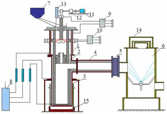
An experimental setup for plasma gasification of SFs was used to verify the TERRA program. The experimental setup and methodology are explained in detail in [7]. To achieve local thermodynamic equilibrium, i.e., phase and chemical equilibrium in the reactor, uniform high-temperature distribution in the reaction zone was ensured by rotating an electric arc across the reactor cross-section. This rotation was achieved using a constant magnetic field from an electromagnetic coil encircling the reactor. The high temperature in the reactor, in accordance with the Arrhenius law, contributed to the accelerated rates of multiple chemical reactions and a reduction in the residence time of the reactants (coal and steam) required to complete the gasification process. To ensure uniform mixing of coal dust and steam in the reactor cover, two ejectors were used. This was done to minimize discrepancies between thermodynamic equilibrium conditions and experimental data. Figure 1 shows the experimental setup implementing these conditions. The height of reactor 1 is 0.3 m, and the diameter is 0.15 m. The electric power of the plasma setup was 70 kW with a thermal efficiency of 55%. The thermal efficiency of the installation was determined by the calorimetry of its components. The experiments lasted 1 h. The average size of KAC particles was 75 μm. Before gasification, the coal dust was dried. The actual operating pressure in the environment was 0.093 MPa. Electric arcs were ignited between rod and ring graphite electrodes in a combined DC plasma reactor (1), in which arc heat release and reaction heat absorption were combined. Then, SF dust from the dust feeder (7) was sprayed with steam from the steam generator (13) through ejectors in the reactor cover. Coal dust consumption was controlled by the speed of the dust feeder dispenser (7), and steam consumption was measured using a Prowirl-77 flowmeter. SF gasification in a flow reactor is a steady-state process apart from the reactor warm-up period required to reach steady-state thermal conditions, after which all gasification process parameters were measured. The steam-fuel mixture was heated to high temperatures by an electric arc rotating in a magnetic field and was subjected to gasification. The gasification products were removed into the ventilation system through the slag and gas separation chamber (2), the chamber of synthesis gas cooling and removal (4), and the chamber of hydration (6). The solid residue formed as a result of the process was removed through the diaphragm into the slag and gas separation chamber (2) and then into the slag trap (3). As a result of the experiments, based on the reduction of material and heat balances, the main parameters of the SF plasma gasification process were determined. Gas samples were taken from the chamber of synthesis gas cooling and removal (4) and analyzed using a gas chromatograph “Khromatek-Gazohrom-2000”. To find the degree of carbon gasification XC according to Formula (1), after switching off the unit, solid residue was collected, which was analyzed using the absorption–weight method [26].
where Cin and Cfin are the initial and final amounts of carbon in SF and condensed products of its gasification.
Figure 1.
Experimental setup for plasma gasification of SF: 1—flow reactor (gasifier); 2—gas and slag separator chamber and orifice; 3—slag trap; 4—synthesis-gas cooling and removal chamber; 5—gas-flow measurement system; 6—hydration chamber; 7—pulverized-coal feeder; 8—the cooling system of the installation units; 9, 10—electric power supply system; 11, 12—motorized electrode position system; 13—water steam generator; 14—safety valve; 15—stand for slag trap.
The specific energy consumption was determined based on power meter readings and reagent consumption. To determine the specific energy consumption in the calculations, we used Formula (2) [17]:
where IT and I298 [kJ/kg] are the total enthalpy of the working fluid (SF + steam) at the current temperature of the gasification process and the initial enthalpy at a temperature of 298 K, respectively.
The material and heat balances of the setup during KAC plasma–steam gasification are presented in Table 2 and Table 3. The exhaust gas flow rate was measured at the 40th minute of the experiment. The discrepancy in the material balance is within 6%. The maximum heat losses were observed in the plasma reactor. Heat balance discrepancy is within 3.7%. By substituting the found material components and heat balances into the TERRA program, the average mass temperature in the reactor was determined to be 3000 K.
Table 2.
Material balance of the plasma installation.
Table 3.
Heat balance of the plasma installation.
A comparison of the results of the plasma–steam gasification of KAC and some other coals shown in Table 1 with the thermodynamic calculations is reported in Table 4. Based on the table, the ash content and volatile yield of SF range from 2.95 to 88% and from 5 to 50%, respectively. It is evident from the table that the yield of the target product (synthesis gas) for all SF during plasma–steam gasification is quite high and varies in the range of 81.7–99.3%. In the case of KAC, the yield of synthesis gas in the experiment is 96.0%, and in the calculation—97.3%. The ballast impurities (Y) obtained in the experiment consist of 2.4% CO2 and 1.6% N2. The calculated Y consists of 0.26% CO2, 2% H2O, and 0.44% N2. The discrepancy between the calculation and the experiment is 1.3%. The degree of gasification of KAC carbon in the experiment reaches 95.3%, which leads to a discrepancy between the experiment and the calculation of 4.7%. The discrepancy in specific energy consumption (QSP) is 6%. The discrepancy between the calculation and the experiment in the main integral indicators (synthetic gas concentration, carbon gasification degree, and specific energy consumption for the plasma–steam gasification process) for the remaining SF from Table 4 varies in the ranges of 1–7%, 5–42%, and 1–23%. A relatively high maximum discrepancy between the calculation and the experiment in terms of the degree of SF gasification and specific energy consumption is observed for plasma–steam gasification of EDS (XC = 29.6%, QSP = 23%) and CP (XC = 21.4%). The significant discrepancy in carbon gasification efficiency is due to the abnormally high ash content of EDS (88%) and the abnormally low yield of CP volatiles (5%) compared to other SFs. EDS has a very high ash content, which hinders oxidizer molecules from diffusing to the carbon, which is uniformly distributed inside the particle and has a very low concentration (8.33%). This slows down the carbon gasification process and increases the required residence time for the reactants in the reactor. The volatile yield determines the reactivity of SF; the lower the volatile yield, the lower the reactivity of SF. The reactivity of CP with a volatile yield of 5% is very low. Its gasification requires an increased residence time for the reactants in the reactor, which is practically impossible in a compact flow reactor. Thus, the actual gasification process of high-ash EDS and low-reactivity CP deviates significantly from thermodynamic equilibrium. Slag formation can reduce heat transfer to the reactor walls, improving heat loss and reactor efficiency, as measured experimentally. According to TERRA thermodynamic code verification, the discrepancy in carbon gasification does not exceed 10%, except for oil shale with abnormally high ash content (88%) and petroleum coke with abnormally low volatile matter yield (5%). It should be noted that the comparison of the calculated and experimental data showed that the discrepancy for SF with moderate ash content and sufficient yield of volatiles was significantly smaller than for SF with higher ash content and low yield of volatiles. Plasma–steam gasification of SFs containing 9 and 88% ash and 48% and 50% volatile yield shows a 12% reduction in specific energy consumption. Plasma–steam gasification of SFs with volatile yields of 48 and 5% and ash contents of 9% and 3%, respectively, results in a 60% reduction in specific energy consumption. The comparison of the calculation and experiments carried out in the combined plasma gasifier showed generally, with the exception of EDS and CP, satisfactory agreement with the obtained results (synthesis gas concentration, degree of SF gasification, and specific energy costs for the process). For calculating plasma–steam gasification of SF, the TERRA program was verified to work correctly. Assuming that one should conclude that the gasification process in a flow plasma reactor can be modeled using the thermodynamic program TERRA. Based on this statement, a generalizing thermodynamic analysis of plasma–steam gasification of SF with different characteristics was carried out.
Table 4.
Comparison of experimental and calculated data.
3. Thermodynamic Simulation
Various SFs (bituminous and brown coals, shale, and petroleum coke) were used for the calculations. SF compositions are presented in Table 1 [7,17,20,26]. The calculations were made for a pressure of 0.101 MPa (atmospheric) and a temperature range of 600 to 3000 K. In selecting the steam consumption for gasification of the SF, oxygen content in the organic mass was considered. Based on the carbon steam gasification reaction, all SFs had a carbon to oxygen mass ratio of 0.75, corresponding to carbon oxidation to carbon monoxide. Table 1 presents the fuel–steam mixture compositions used in the calculations.
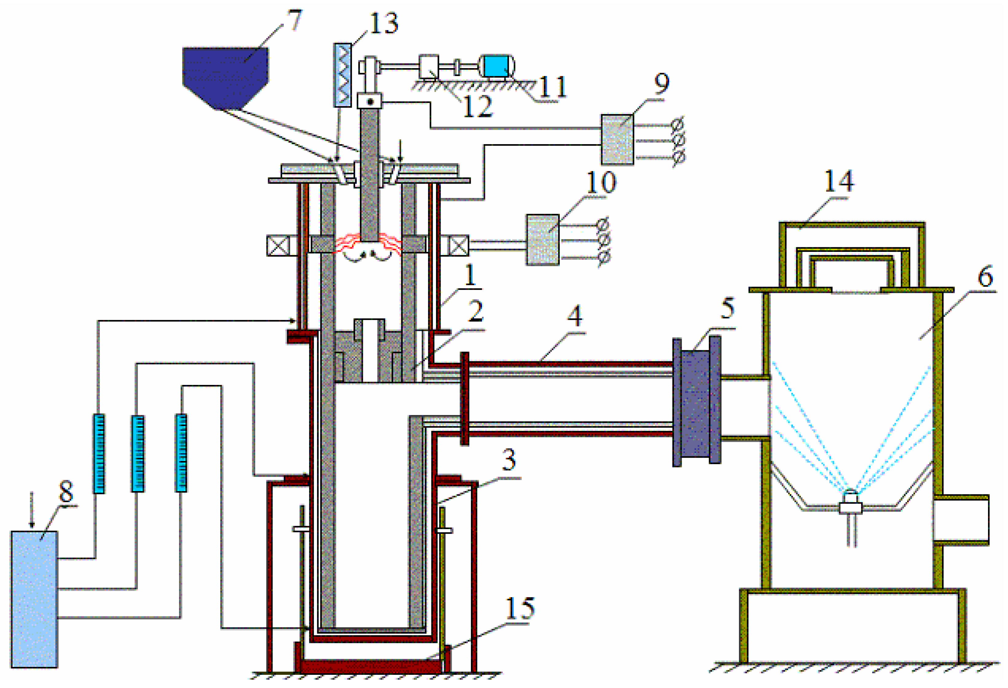
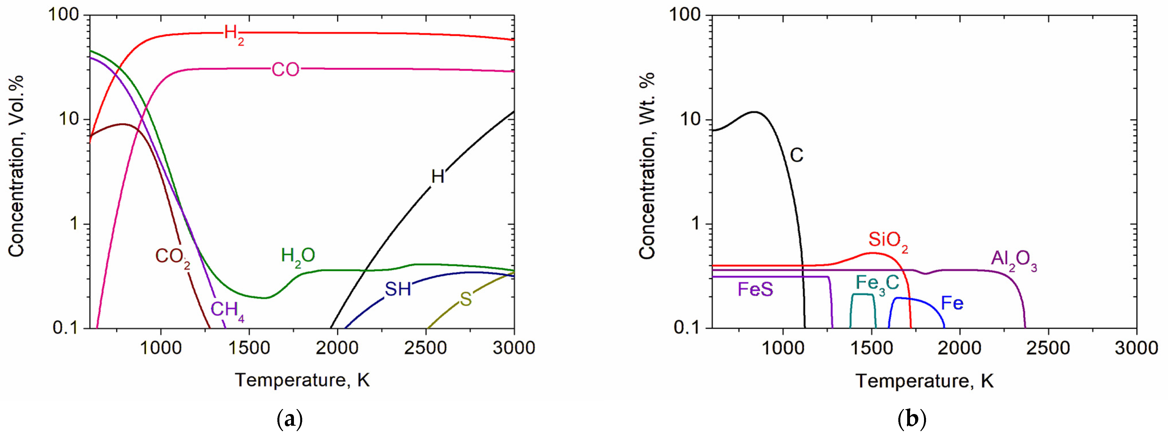
The compositions of the products of plasma gasification of solid fuels are calculated for all SFs in Table 1. Let us consider the graphical dependencies of the concentrations of components of the gas and condensed phases using, for example, CP, EBC, and EDS representing SFs with minimum, average, and maximum ash content from the range under study. The CP steam gasification products are shown in Figure 2. At temperatures exceeding 1200 K, synthesis gas dominates the gas phase of gasification products (Figure 2a), reaching a maximum concentration of 98.9% at 1600 K. The total concentration of atomic and molecular hydrogen (68%) is higher than that of carbon monoxide (CO)—30.9%. Synthesis gas has a heat of combustion of 11,248 kJ/m3 (17,303 kJ/kg). With increasing temperature, the CO concentration decreases to 28.8% at 3000 K, while the total concentration of molecular and atomic hydrogen (H2 + H) increases to 69.7%. A slight decrease in synthesis gas concentration with increasing temperature is due to the appearance of sulfur-containing components (SH and S) in the gas phase. As for the condensed phase (Figure 2b), when the temperature increases to 2500 K, all its components pass into the gas phase. Figure 2a shows no minerals in the gas phase due to their low concentration (less than 0.1%) caused by CP’s low ash content.
Figure 2.
Concentrations of gaseous (a) and condensed (b) components during steam gasification of CP depending on temperature.
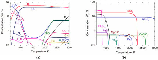
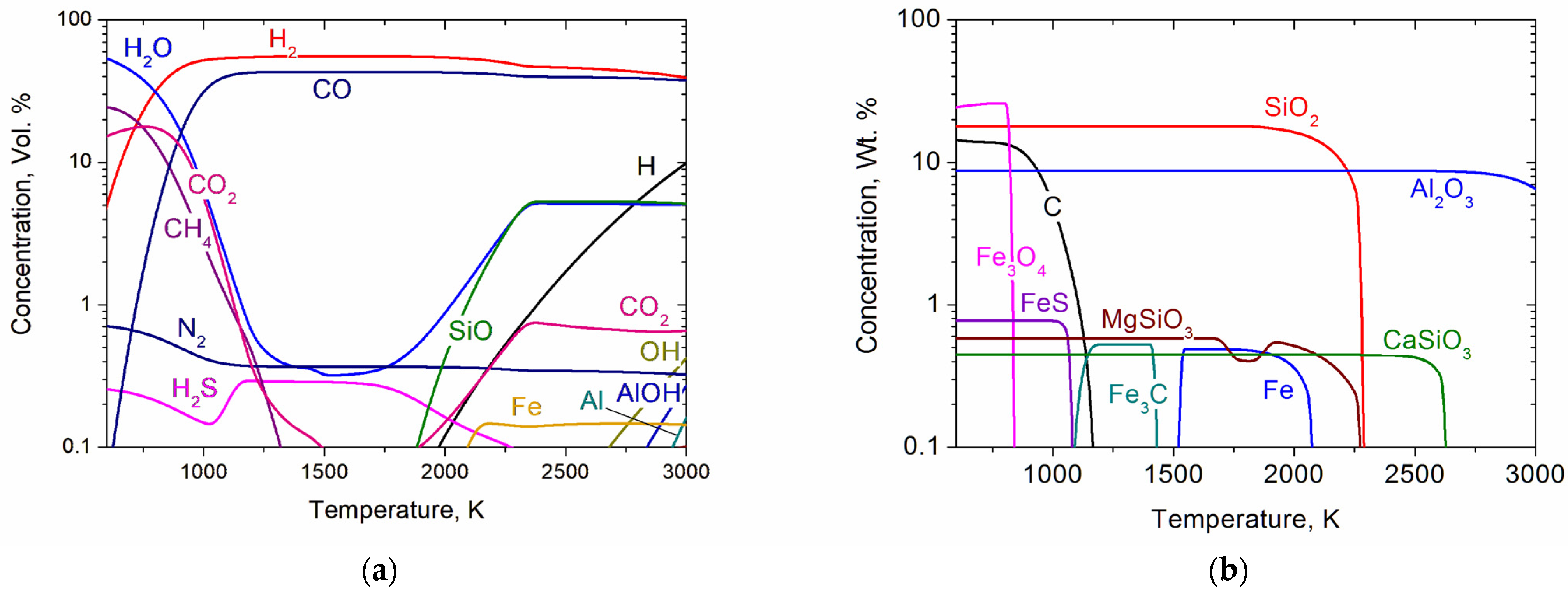
Figure 3 shows the composition of bituminous coal steam gasification products. The gas phase of gasification products (Figure 3a) at a temperature exceeding 1200 K is mainly synthesis gas, the maximum concentration of which reaches 98.9% at 1600 K. At the same time, the total concentration of hydrogen (55.6%) is higher than CO—43.3%. The heat of combustion of the synthesis gas is 11,475 kJ/m3 (17,654 kJ/kg). With increasing temperature, the concentrations of carbon monoxide and hydrogen decrease to 37.8% and 49.2% at 3000 K, respectively. A noticeable decrease in the concentration of the synthesis gas to 87.1% with increasing temperature is associated with the appearance of components of the mineral mass of coal in the gas phase beginning to pass from the condensed phase to the gas phase at a temperature above 2100 K (Figure 3b). At temperatures above 2000 K, the mineral components of coal are represented in the gas phase by the elements Fe, Al, and the compounds SiO and AlOH. When the temperature increases from 600 K to 2600 K, most of the condensed phase components (Fe3O4, FeS, C, Fe3C, Fe, MgSiO3, SiO2, CaSiO3) pass into the gas phase at corresponding temperatures (Figure 3b). Over 2750 K, the Al2O3 concentration begins to decrease.
Figure 3.
Concentrations of gaseous (a) and condensed (b) components during steam gasification of EBC depending on temperature.
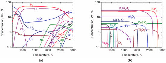
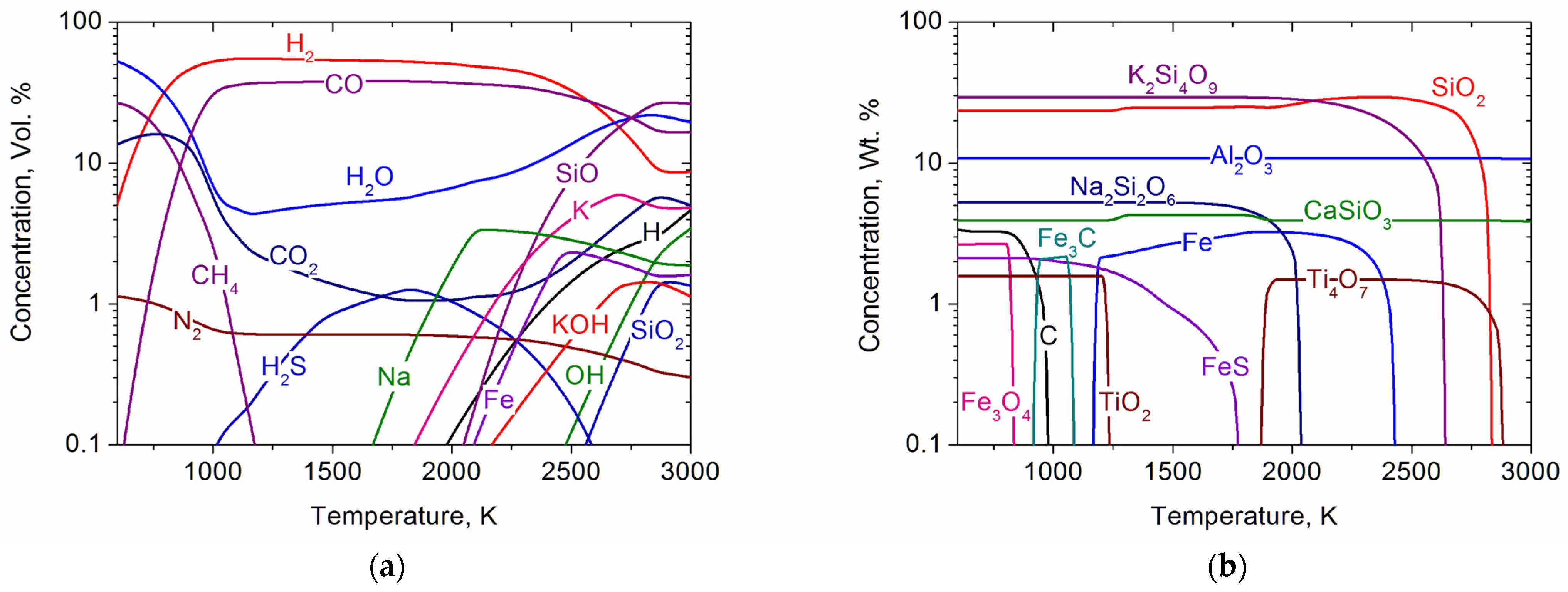
Figure 4 shows the composition of EDS steam gasification products. The gas phase of gasification products (Figure 4a) at temperatures exceeding 1200 K is predominantly synthesis gas, the maximum concentration of which reaches 92.5% at 1200 K. The total concentration of hydrogen (55.3%) is higher than that of CO (37.2%). The heat of combustion of the synthesis gas is 10,672 kJ/m3 (16,418 kJ/kg). The synthesis gas is diluted with oxidizers: H2O at 4.4% and CO2 at 2.2%. During the temperature increase, the carbon monoxide and hydrogen concentrations fall to 16.6% and 13.3%, respectively, at 3000 K, while the H2O and CO2 concentrations rise to 19.5% and 5.0%. The maximum concentration of hydrogen sulfide (H2S) does not exceed 1.3%. In contrast to the above cases, molecular nitrogen (N2) is observed in the gas phase at a concentration not exceeding 1%. A significant decrease in the concentration of synthesis gas (up to 29.9%) with increasing temperature is associated with the appearance of the mineral mass of shale components in the gas phase, which begin to transit from the condensed phase to the gas phase at temperatures above 1700 K (Figure 4b). At temperatures above 2250 K, EDS mineral components are represented in the gas phase by the elements Na, K, Fe, Al, and the compounds SiO, KOH, and SiO2. As the temperature increases from 600 to 2900 K, most of the condensed phase components (Fe3O4, FeS, C, Fe3C, TiO2, FeS, Na2Si2O6, Fe, K2Si4O9, SiO2, and Ti4O7) transit to the gas phase at significantly different temperatures (Figure 4b). The concentrations of Al2O3 and CaSiO3 in the temperature range of 600 to 3000 K remain virtually unchanged. From a comparison of Figure 2, Figure 3 and Figure 4, it follows that despite the significant difference in the ash content of SFs (from 3 to 88%), the main gaseous product of their gasification is synthesis gas with a predominance of hydrogen over carbon monoxide. For all SFs, the maximum concentration of synthesis gas is achieved in the temperature range of 1200–1600 K, with a minimum concentration of ballasting impurities (H2O, CO2, N2, etc.). The heat of combustion of synthesis gas obtained by steam gasification of SF 1–10 varies in the range of 10,475–11,570 kJ/m3 (16,115–17,800 kJ/kg).
Figure 4.
Concentrations of gaseous (a) and condensed (b) components during the steam gasification of EDS, depending on temperature.
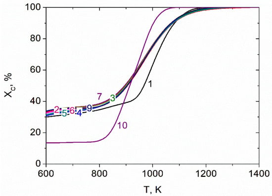
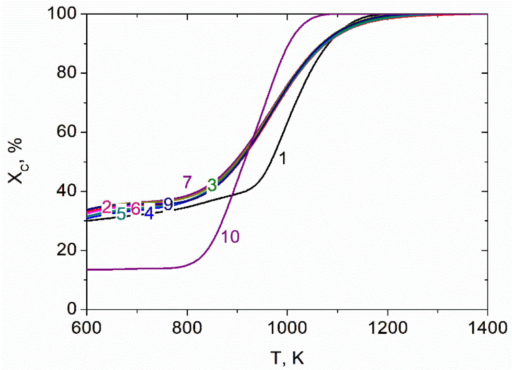
Figure 5 shows the temperature dependence of the SF gasification degree. The figure shows that the gasification degree increases with temperature, reaching 100% for all calculation options. For all SF considered, carbon completely passes into the gas phase as CO by 1300 K. The temperature curves for SF 2 to 9 practically coincide with the achievement of complete gasification of SF carbon in the range of 1250 to 1300 K. As for curve 1, in the temperature range of 600 to 1100 K, the degree of gasification of CP is lower than that for SF 2 to 9. The complete gasification of CP has already been achieved at 1200 K. The degree of gasification of EDS (curve 10) in the temperature range of 600 to 900 K is lower than that for SF 1 to 9, but already at T = 1100 K, complete gasification of EDS is achieved.
Figure 5.
Degree of carbon gasification of various solid fuels (Table 1) during steam gasification, depending on temperature.
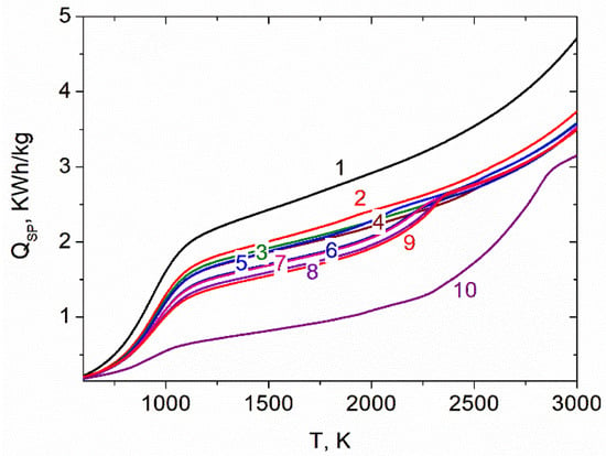
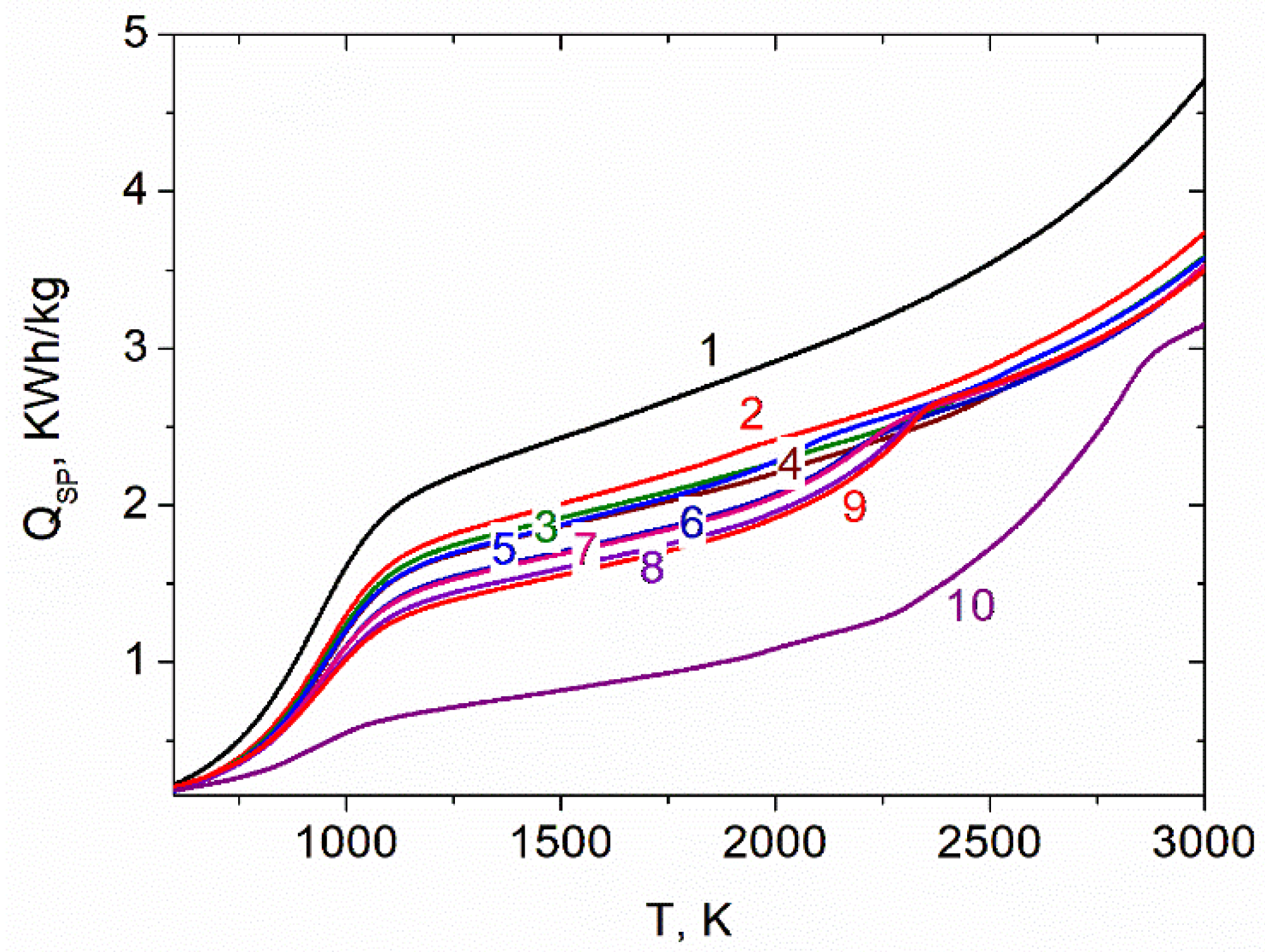
Figure 6 shows the temperature dependence of specific energy consumption for the SF gasification process. It is evident from the figure that QSP increases smoothly with temperature for all SFs. In the temperature range of 1250 to 1750 K, when the concentration of synthesis gas is maximum and practically does not change, the specific energy consumption for all options varies over a wide range (from 0.7 to 2.7 kWh/kg). For SF 2 to 9, their values range from 1.4 to 2.2 kWh/kg. As for CP gasification (curve 1), the QSP in the temperature range of 600 to 3000 K exceeds that for SF 2 to 10 due to low yield volatiles (5%). The relatively low QSP for EDS gasification (curve 10) is due to the high yield of volatiles (50%) and the low organic matter content (12%).
Figure 6.
Specific energy consumption for the steam gasification process of various solid fuels (Table 1), depending on temperature.
Experimental and computational studies enable the evaluation of the efficiency of scaling a plasma setup for the production of synthesis gas. The plasma setup’s power supply chain has an electrical efficiency of 95%. Thermal efficiency of 55% determines heat loss in the setup. When scaling the plasma plant from 70 to 705 kW, its energy efficiency increased to 61%, with coal consumption of 150 kg/h [26]. This scaling is estimated to result in a synthesis gas production cost of $103 per ton, which is 60% lower than that of conventional synthesis gas production techniques [17].
4. Conclusions
The experiment performed on plasma–steam gasification of brown coal with an ash content of 9% and a volatile yield of 48% and a comparison of calculated and experimental data, as well as a comparison of calculated and experimental integral indicators for the plasma–steam gasification of various solid fuels, showed satisfactory agreement. For solid fuels with moderate ash content and sufficient yields of volatile substances, there is a significantly smaller discrepancy between the experiment and the calculation than for solid fuels with high ash content and low volatile content. The conducted studies allowed us to verify the TERRA thermodynamic calculation program. A thermodynamic analysis of plasma–steam gasification of solid fuels with significantly different properties was performed using the TERRA program.
In the thermodynamic analysis, it was shown that the plasma–steam gasification of solid fuels is a possible method for producing high-calorie synthesis gas. The gasification of solid fuels produces synthesis gas with a predominance of hydrogen over carbon monoxide, despite the significant differences in the ash content between them (from 3 to 88%). For all solid fuels, the maximum concentration of synthesis gas is achieved in the temperature range of 1200 to 1600 K, with a minimum concentration of ballast impurities (H2O, CO2, N2). The heat of combustion of synthesis gas varies in the range of 10,475–11,570 kJ/m3 (16,115–17,800 kJ/kg).
For all calculation options in the temperature range of 1250–1300 K, solid fuel carbon undergoes 100% gasification regardless of the amount of ash.
The specific energy consumption for the solid fuel gasification process increases with the temperature for all solid fuels. In the temperature interval characteristic of the maximum synthesis gas concentration, the specific energy consumption for all options varies in the range of 0.7 to 2.7 kWh/kg. For solid fuel plasma–steam gasification, increasing the volatile yield reduces specific energy consumption, but the ash content has little effect.
Plasma processing of solid fuels for synthesis gas production can be optimized by using the TERRA program.
WORDTUNE, an AI-powered writing assistant, was used to improve readability during the preparation of this work. After using this tool/service, the authors reviewed and edited the content as needed and take full responsibility for the content of the publication.
Author Contributions
Conceptualization, V.E.M. and A.B.U.; methodology, M.N.O., V.E.M., A.B.U. and S.K.A.; software, M.N.O. and A.B.U.; validation, M.N.O., V.E.M., A.B.U. and S.K.A.; formal analysis V.E.M. and S.K.A.; investigation, M.N.O., V.E.M. and A.B.U.; resources, M.N.O. and S.K.A.; data curation, V.E.M. and S.K.A.; writing—original draft preparation, M.N.O., V.E.M., A.B.U. and S.K.A.; writing—review and editing, V.E.M. and A.B.U.; visualization, M.N.O. and A.B.U.; supervision, V.E.M.; project administration, M.N.O. and S.K.A.; funding acquisition, M.N.O. and S.K.A. All authors have read and agreed to the published version of the manuscript.
Funding
This work was supported by the Committee of Science of the Ministry of Science and Higher Education of the Republic of Kazakhstan [grants number AP22687016 and BR27199117].
Data Availability Statement
The data is reported in the manuscript.
Conflicts of Interest
The authors declare no conflicts of interest.
Abbreviations
The following abbreviations are used in this manuscript:
| BBC | Borlinsk bituminous coal |
| CFD | Computational fluid dynamics |
| CP | Canadian petcoke |
| EBC | Ekibastuz bituminous coal |
| EDS | Estonian Dictyonema shale |
| KAC | Kansko–Achinsk brown coal |
| NBC | Nizhneilli brown coal |
| PBC | Podmoskovnyi brown coal |
| PRBC | Powder River Basin bituminous coal |
| SF | Solid fuel |
| TBC | Tugnuisk bituminous coal |
| TRBC | Turgai brown coal |
References
- Tahir, M.U.; Guo, S. Preliminary Investigation of Fracture Behavior during Carbon Dioxide Fracturing of Natural Hydrogen Reservoir with Hard-Core Imperfections. Reserv. Sci. 2026, 2, 34–51. [Google Scholar] [CrossRef] [Scilit]
- Wu, J.; Ansari, U. From CO2 Sequestration to Hydrogen Storage: Further Utilization of Depleted Gas Reservoirs. Reserv. Sci. 2025, 1, 19–35. [Google Scholar] [CrossRef] [Scilit]
- Higgins, P.; Foley, A. The evolution of offshore wind power in the United Kingdom. Renew. Sustain. Energy Rev. 2014, 37, 599–612. [Google Scholar] [CrossRef] [Scilit]
- Wang, Y.; Ning, H.; Sun, Y. Simulation research on optimization of a 200 MW IGCC system. Appl. Energy Combust. Sci. 2023, 16, 100219. [Google Scholar] [CrossRef] [Scilit]
- Janajreh, I.; Raza, S.S.; Valmundsson, A.S. Plasma gasification process: Modeling, simulation and comparison with conventional air gasification. Energy Convers. Manag. 2013, 65, 801–809. [Google Scholar] [CrossRef] [Scilit]
- Hong, Y.C.; Lee, S.J.; Shin, D.H.; Kim, Y.J.; Lee, B.J.; Cho, S.Y.; Chang, H.S. Syngas production from gasification of brown coal in a microwave torch plasma. Energy 2012, 47, 36–40. [Google Scholar] [CrossRef] [Scilit]
- Messerle, V.E.; Ustimenko, A.B.; Lavrichshev, O.A. Plasma coal conversion including mineral mass utilization. Fuel 2017, 203, 877–883. [Google Scholar] [CrossRef] [Scilit]
- Kumabe, K.; Hanaoka, T.; Fujimoto, S.; Minowa, T.; Sakanishi, K. Co-gasification of woody biomass and coal with air and steam. Fuel 2007, 86, 684–689. [Google Scholar] [CrossRef] [Scilit]
- Mourão, R.; Marquesi, A.R.; Gorbunov, A.V.; Filho, G.P.; Halinouski, A.A.; Otani, C. Thermochemical Assessment of Gasification Process Efficiency of Biofuels Industry Waste with Different Plasma Oxidants. IEEE Trans. Plasma Sci. 2015, 43, 3760–3767. [Google Scholar] [CrossRef] [Scilit]
- Liu, B.; Tu, X. Plasma Coal Gasification for Syngas Production. In Molecular Sciences and Chemical Engineering; Elsevier: Amsterdam, The Netherlands, 2024. [Google Scholar] [CrossRef] [Scilit]
- İbrahimoglu, B.; İbrahimoglu, B.; Bolayır, E. A Comparative Study on Plasma Gasification of Lignite Coal. Res. Dev. Mater. Sci. 2022, 16, 1826–1830. [Google Scholar] [CrossRef] [Scilit]
- Serov, A.; Hrabovský, M.; Kopecký, V.; Mašláni, A.; Hlína, M.; Hurba, O. Lignite Gasification in Thermal Steam Plasma. Plasma Chem. Plasma Process. 2019, 39, 395–406. [Google Scholar] [CrossRef] [Scilit]
- Zhovtyansky, V.A.; Petrov, S.V.; Lelyukh, Y.I.; Nevzglyad, I.O.; Goncharuk, Y.A. Efficiency of Renewable Organic Raw Materials Conversion Using Plasma Technology. IEEE Trans. Plasma Sci. 2013, 41, 3233–3239. [Google Scholar] [CrossRef] [Scilit]
- Favas, J.; Monteiro, E.; Rouboa, A. Hydrogen production using plasma gasification with steam injection. Int. J. Hydrogen Energy 2017, 42, 10997–11005. [Google Scholar] [CrossRef] [Scilit]
- He, X.; Ma, T.; Qiu, J.; Sun, T.; Zhao, Z.; Zhou, Y.; Zhang, J. Mechanism of coal gasification in a steam medium under arc plasma conditions. Plasma Sources Sci. Technol. 2004, 13, 446–453. [Google Scholar] [CrossRef] [Scilit]
- Qiu, J.; He, X.; Sun, T.; Zhao, Z.; Zhou, Y.; Guo, S.; Zhang, J.; Ma, T. Coal gasification in steam and air medium under plasma conditions: A preliminary study. Fuel Process. Technol. 2004, 85, 969–982. [Google Scholar] [CrossRef] [Scilit]
- Galvita, V.; Messerle, V.E.; Ustimenko, A.B. Hydrogen production by coal plasma gasification for fuel cell technology. Int. J. Hydrogen Energy 2007, 32, 3899–3906. [Google Scholar] [CrossRef] [Scilit]
- Li, Y. Efficient and Clean Coal Gasification by Dielectric barrier discharge plasma. In Proceedings of the IEEE International Conference on Plasma Science (ICOPS), Beijing, China, 16–20 June 2024. [Google Scholar] [CrossRef] [Scilit]
- Yoon, S.J.; Lee, J.-G. Hydrogen-rich syngas production through coal and charcoal gasification using microwave steam and air plasma torch. Int. J. Hydrogen Energy 2012, 37, 17093–17100. [Google Scholar] [CrossRef] [Scilit]
- Messerle, V.E.; Ustimenko, A.B. Plasma processing of uranium containing solid fuels. Fuel 2019, 242, 447–454. [Google Scholar] [CrossRef] [Scilit]
- Lyubina, Y.L.; Suris, A.L. Thermodynamic model of the plasma gasification of organic solid wastes. Chem. Pet. Eng. 1999, 35, 403–406. [Google Scholar] [CrossRef] [Scilit]
- Slavinskaya, N.A. Chemical Kinetic Modeling in Coal Gasification Processes: An Overview. In Proceedings of the ASME Turbo Expo 2010: Power for Land, Sea, and Air, Glasgow, UK, 14–18 June 2010. [Google Scholar] [CrossRef] [Scilit]
- Ibrahimoglu, B.; Yilmazoglu, M.Z. Numerical modeling of a downdraft plasma coal gasifier with plasma reactions. Int. J. Hydrogen Energy 2020, 45, 3532–3548. [Google Scholar] [CrossRef] [Scilit]
- Matveev, I.B.; Serbin, S.I. Modeling of the Coal Gasification Processes in a Hybrid Plasma Torch. IEEE Trans. Plasma Sci. 2007, 35, 1639–1647. [Google Scholar] [CrossRef] [Scilit]
- Hasse, C.; Debiagi, P.; Wen, X.; Hildebrandt, K.; Vascellari, M.; Faravelli, T. Advanced modeling approaches for CFD simulations of coal combustion and gasification. Prog. Energy Combust. Sci. 2021, 86, 100938. [Google Scholar] [CrossRef] [Scilit]
- Gorokhovski, M.; Karpenko, E.I.; Lockwood, F.C.; Messerle, V.E.; Trusov, B.G.; Ustimenko, A.B. Plasma Technologies for Solid Fuels: Experiment and Theory. J. Energy Inst. 2005, 78, 157–171. [Google Scholar] [CrossRef] [Scilit]

Disclaimer/Publisher’s Note: The statements, opinions and data contained in all publications are solely those of the individual author(s) and contributor(s) and not of MDPI and/or the editor(s). MDPI and/or the editor(s) disclaim responsibility for any injury to people or property resulting from any ideas, methods, instructions or products referred to in the content. |
© 2026 by the authors. Licensee MDPI, Basel, Switzerland. This article is an open access article distributed under the terms and conditions of the Creative Commons Attribution (CC BY) license.