1. Introduction
Sliding mode control (SMC) is a well-established robust control methodology for uncertain nonlinear systems [
1,
2,
3]. In continuous time, SMC achieves exact compensation of matched bounded perturbations in finite time. However, digital implementation via sample-and-hold limits the existence of an ideal sliding mode [
4]. As a result, the trajectory is confined to a neighborhood of the sliding surface known as the quasi-sliding mode band [
5].
Several discrete-time SMC formulations have been proposed to address the intrinsic limitations of sampling. Sarpturk et al. [
6] investigated stability conditions for discrete-time systems with matched uncertainties. Furuta [
7] developed a discrete-time sliding mode controller for linear systems with parametric uncertainties. Misawa [
8] developed a saturation-based controller that handles both unmatched uncertainties and uncertain control gain. This controller established boundary-layer attractivity through a discrete Lyapunov argument. Bartoszewicz [
9] proposed reaching laws tailored to discrete-time implementations, and Bandyopadhyay and Janardhanan [
10] extended the framework to multirate output feedback. More recently, implicit discretization methods have been shown to eliminate numerical chattering entirely [
11,
12,
13]. Reaching law approaches have also been extensively studied; Gao et al. [
5] introduced the quasi-sliding mode concept and proposed systematic reaching laws for discrete-time systems. Fridman et al. [
14] provided a comprehensive treatment of higher-order sliding modes and their discretization. A comprehensive overview of discrete-time sliding mode techniques and their convergence properties can be found in [
15,
16].
A common limitation of the above approaches is the reaching phase. The trajectory must first converge to the sliding surface before the robustness properties take effect. Integral sliding mode (ISM) methodology, introduced by Utkin and Shi [
17] and extended by Cao and Xu [
18] and Rubagotti et al. [
19], eliminates this phase. It does so by constructing a sliding variable that starts at zero at any initial condition, ensuring robustness from the first sampling instant onward.
Complementary to the ISM approach, disturbance estimation techniques have been integrated into discrete-time SMC to further reduce the quasi-sliding band. Su et al. [
20] proposed a past-step estimation scheme that approximates the aggregated perturbation from consecutive samples of the sliding variable. When the estimation is sufficiently accurate, this achieves an improvement from first to second order in the sampling period. Drakunov and Utkin [
21] introduced an observer-based approach to reconstructing unknown inputs in variable-structure systems. These estimation mechanisms are particularly effective when the gain uncertainty is moderate, as the estimation error is proportional to the deviation of the true gain from its nominal value.
The aforementioned discrete-time SMC techniques have found significant application in DC–DC power converters interfaced with photovoltaic (PV) panels. In these systems, the control objective is to regulate the inductor current to track a reference provided by a maximum power point tracking (MPPT) algorithm [
22,
23,
24]. Several works have demonstrated the advantages of SMC-based MPPT over conventional techniques such as Perturb and Observe (P&O) and Incremental Conductance (IC). These advantages include faster convergence and improved tracking under partial shading [
25,
26]. Higher-order approaches, particularly the super-twisting algorithm [
27], have also been incorporated into MPPT controllers for PV systems under irradiance variations [
28]. Recent contributions have further explored SMC techniques for boost converters in renewable energy applications [
29,
30,
31].
Beyond SMC-specific implementations, boost converter topologies for PV-based battery charging with MPPT have been actively studied in the recent literature. The aim is to improve conversion efficiency under varying irradiance conditions [
32].
Extending previous work that explored practical SMC implementations for DC–DC power electronics converters, including a first-order discrete SMC deployed on a low-cost embedded platform [
33] and an integrated sliding-mode control with an adaptive-step MPPT strategy for PV systems [
34], this study advances these contributions. Specifically, it addresses the reaching-gain selection problem under multiplicative gain uncertainty and incorporates disturbance estimation within an ISM framework.
The DC–DC boost converter is a particularly relevant benchmark for discrete-time SMC with multiplicative gain uncertainty. Its control gain depends on the capacitor voltage, which varies with the battery state and the operating point. In a solar battery charging system serving multiple battery banks spanning from 24 V to 72 V, the gain ratio can vary substantially. This places the system well beyond the threshold at which the fixed-gain controller of [
8] fails to contract inside the boundary layer. Moreover, the nominal drift in inductor current dynamics can be substantial in typical designs. This makes the direct application of Misawa’s controller impractical without the drift-cancellation mechanism provided by ISM. These characteristics make the boost converter an ideal testbed for the proposed framework.
This study addresses the identified limitation through four main contributions:
- 1.
An optimal reaching gain, obtained as the unique optimum of a family of admissible reaching gains, that minimizes the worst-case contraction factor over the entire gain-uncertainty interval, guaranteeing contraction inside the boundary layer for every finite uncertainty ratio. This result defines the best achievable factor for the saturation-based reaching law under adversarial gain selection.
- 2.
The integration of the optimal reaching law within a discrete-time ISM framework [
17] eliminates the reaching phase and reduces the effective perturbation in the sliding variable dynamics. This combination is particularly advantageous for high-gain systems such as power converters, where drift mismatch in the direct approach leads to impractically wide boundary layers.
- 3.
A past-step disturbance-estimation mechanism exploits the auxiliary sliding-variable recursion to approximate the additive perturbation. When the gain uncertainty is moderate, it further reduces the quasi-sliding band by one order in the sampling period. The estimation is attenuated by a confidence factor that prevents amplification of the estimation error when the gain deviates significantly from its nominal value.
- 4.
The proposed controller is applied to an MPPT-based solar battery charging system using a DC–DC boost converter. It illustrates robust current regulation across three battery banks under varying irradiance conditions on a switching-level simulation model. The model includes parasitic resistances, semiconductor voltage drops, and switching ripple.
Compared with existing discrete-time SMC approaches, the proposed framework offers three distinct advantages: (i) unlike the fixed-gain design of [
8], the optimal reaching gain guarantees contraction inside the boundary layer for every finite uncertainty ratio, not only for moderate levels; (ii) the ISM structure eliminates the reaching phase, which is present in [
5,
9,
10]; and (iii) the disturbance estimator further reduces the quasi-sliding band from first to second order in the sampling period near the nominal gain, a feature not available in the above references.
The paper is organized as follows.
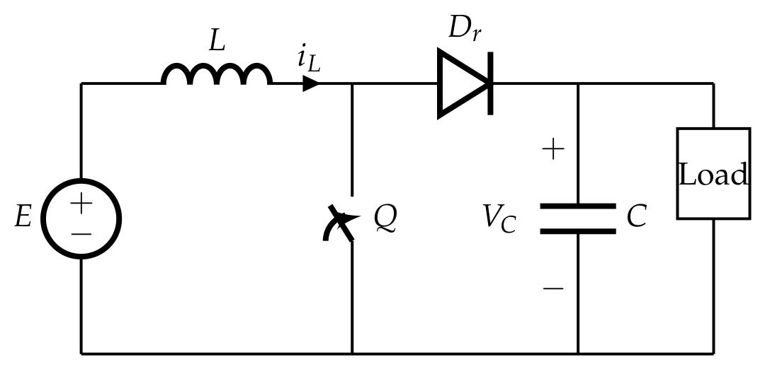
Section 2 introduces notation, preliminary definitions, and the boost converter model.
Section 3 presents the control design, including the ISM structure, the optimal reaching gain, and the disturbance estimation.
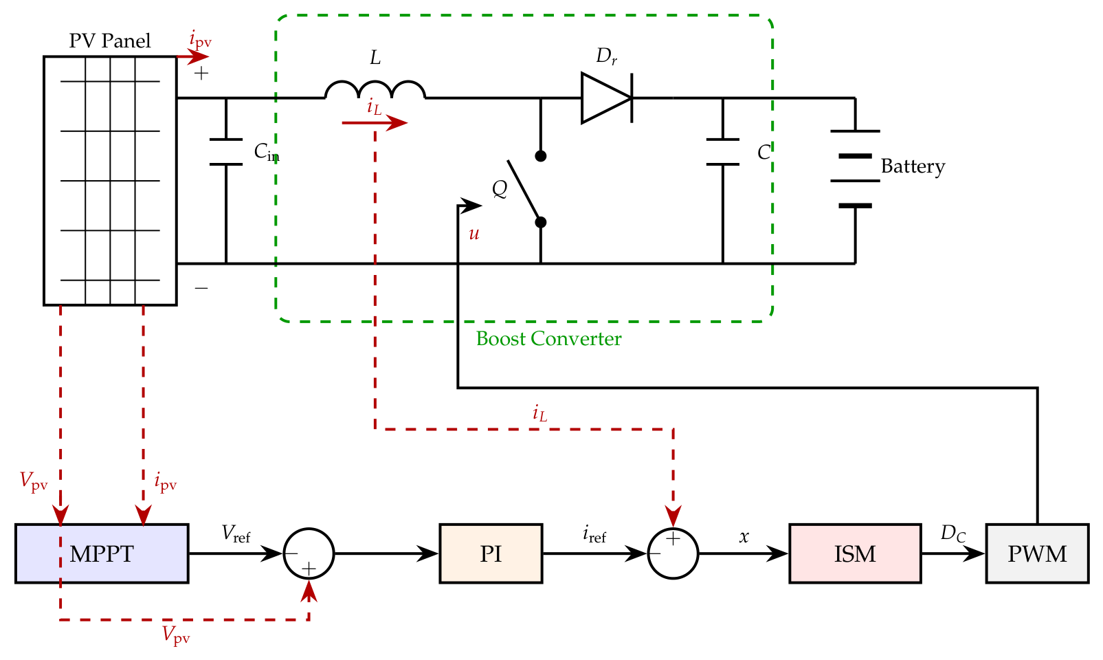
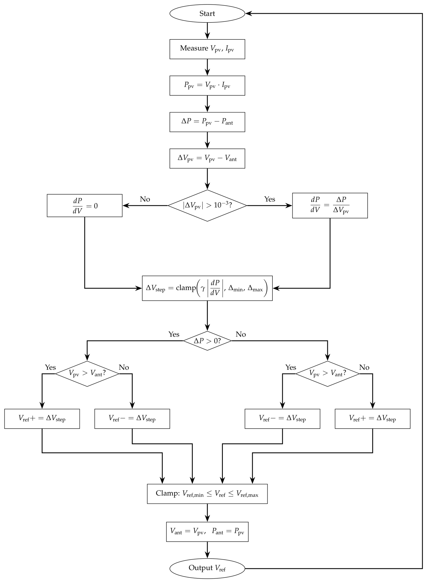
Section 4 describes the specialization of the proposed controller to the PV battery charging system and the MPPT algorithm.
Section 5 presents the simulation results, and
Section 6 concludes the paper.
5. Simulations and Results
The proposed ISM controller with optimal reaching gain and disturbance estimation is illustrated through an analytical comparison and switching-level simulations of the PV-fed boost converter described in
Section 4.
Section 5.1 compares the worst-case contraction factor of the proposed reaching gain against the fixed-gain design of [
8]. The simulations are carried out in MATLAB/Simulink R2023a using the FixedStepDiscrete solver with a fixed step size of
s. To ensure a highly accurate representation of the power stage, SPICE elements are utilized for the semiconductor devices. The representation in Simulink includes the parasitic resistances
and
, and the switching ripple at
kHz, while the controller updates at a sampling rate of
kHz.
Table 4 summarizes the controller and parameters. Three simulation scenarios are then considered: steady-state operation under constant irradiance (
Section 5.2), transient response to irradiance step changes (
Section 5.3) and a comparison with a discrete PI controller (
Section 5.4).
5.1. Analytical Comparison with the Fixed-Gain Design
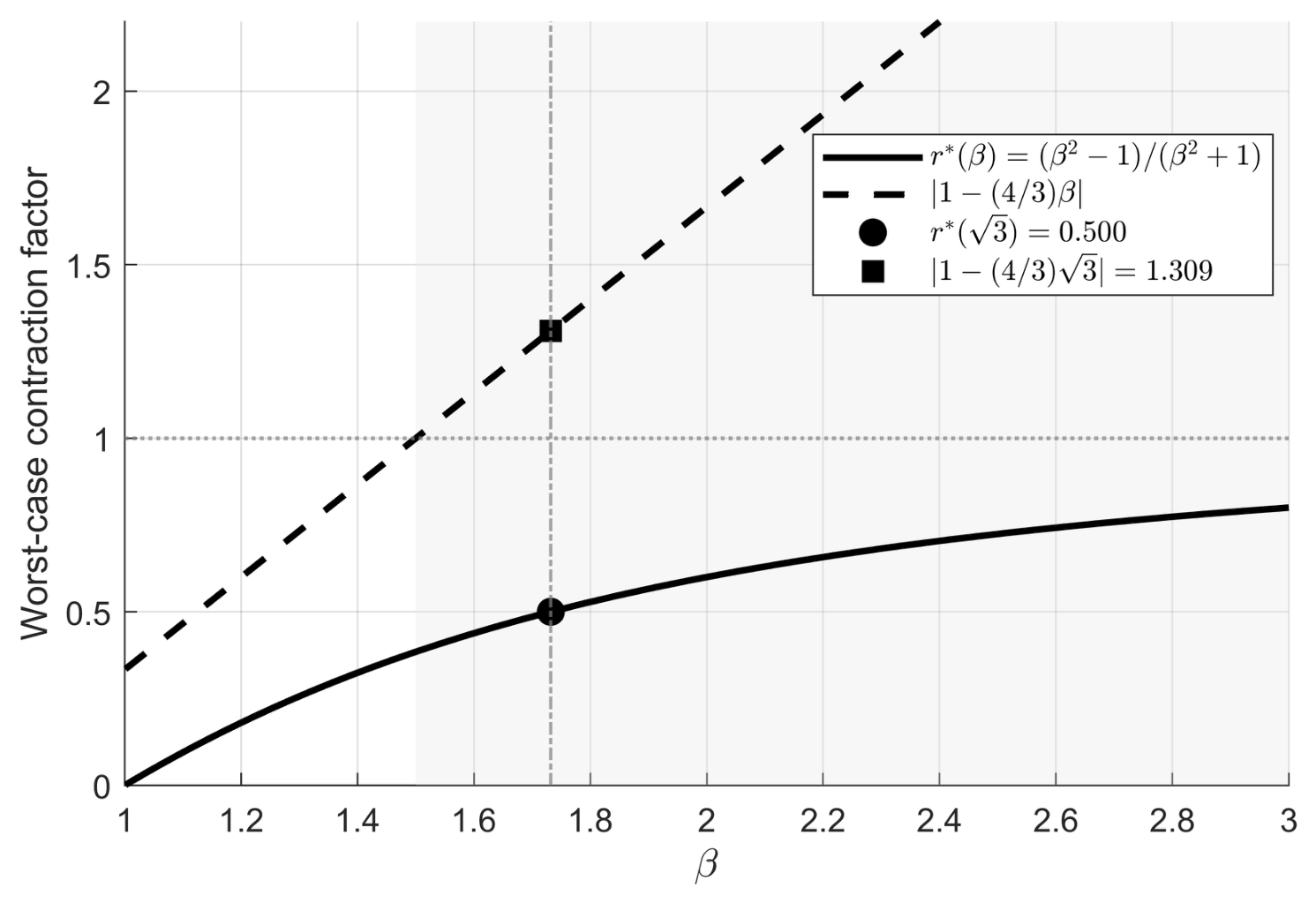
Figure 4 compares the worst-case contraction factors of the proposed reaching gain and the fixed-gain design of [
8] as functions of the uncertainty ratio
. The proposed factor
remains strictly below unity for every finite
, guaranteeing contraction inside the boundary layer regardless of the uncertainty level. In contrast, the fixed gain
(corresponding to the typical choice
,
in [
8]) crosses the contraction boundary at
and grows linearly thereafter. At the converter’s operating point
, the fixed-gain factor reaches
, meaning the inside-layer iteration amplifies
by 31% per step, whereas the proposed gain yields
, halving
at each step.
5.2. System Response Under Constant Irradiance
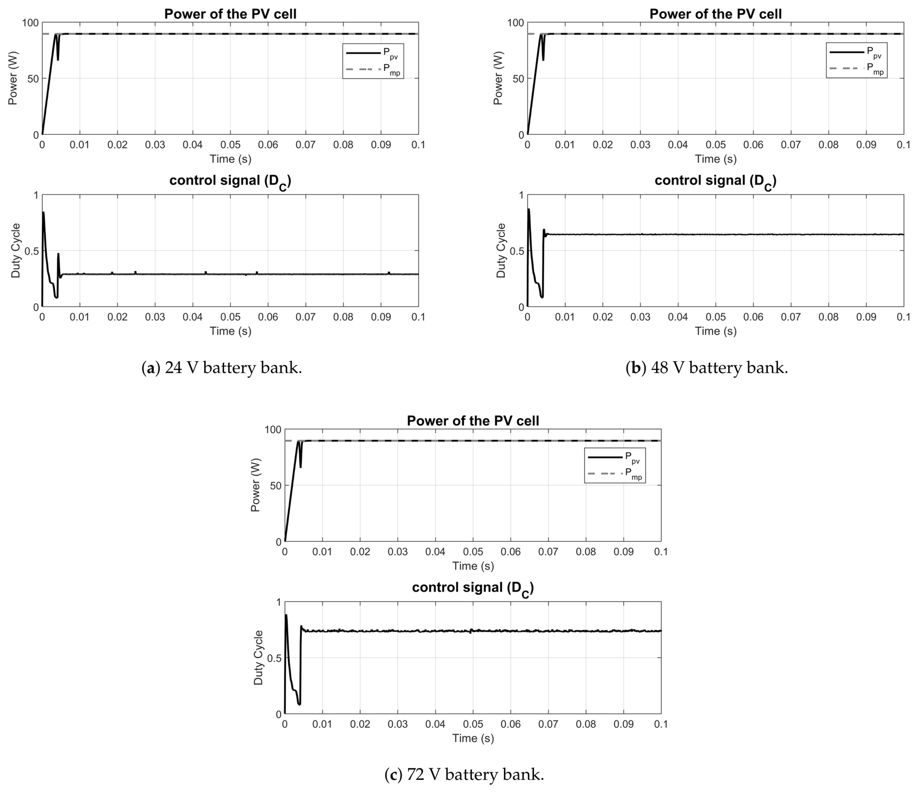
In this scenario, the system operates under standard test conditions ( W/m2, °C) and the MPPT algorithm converges to the MPP. Three battery bank voltages are tested: 24 V, 48 V, and 72 V.
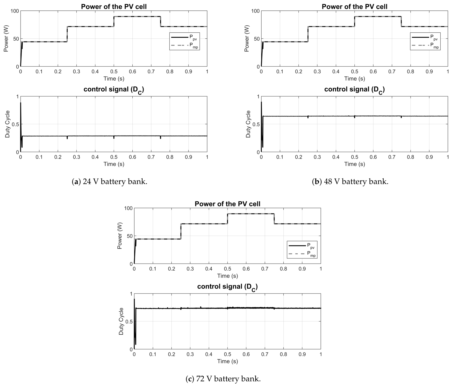
Figure 5 shows the PV panel power extraction and
for each battery bank. In all three cases, the MPPT algorithm converges to the rated power
W, and
settles to the corresponding steady-state operating value
, where
is the converged MPP voltage. The values differ slightly from the lossless formula due to conduction losses in the power stage.
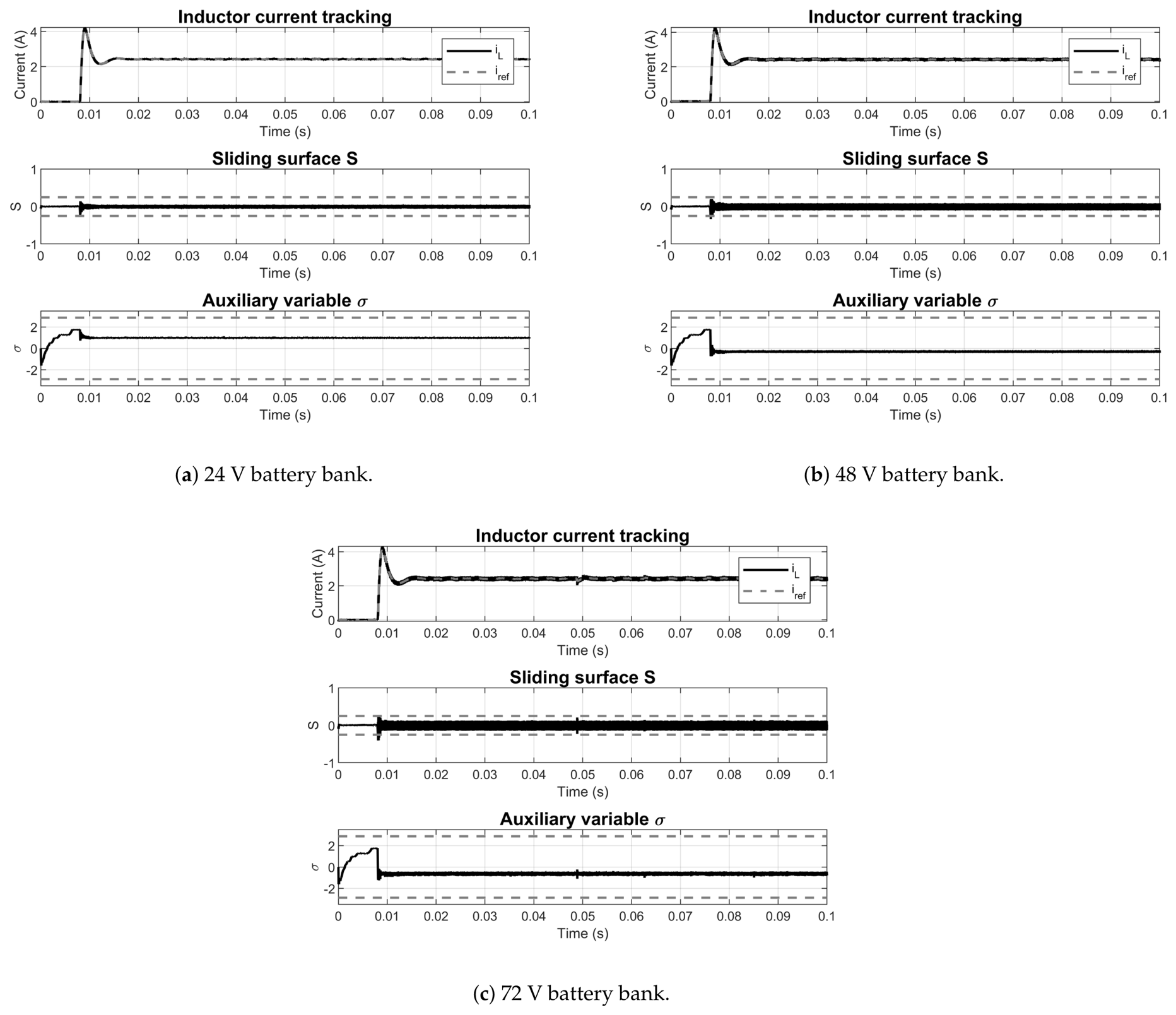
Figure 6 presents the inductor current tracking and the sliding surfaces
S and
for each battery bank. The sliding variable
converges to a neighborhood of zero due to the integral action of
z, while the ISM variable
remains within the boundary layer
. In each subplot, the dashed horizontal lines indicate the theoretical worst-case steady-state bounds: for
S, the bound (
70) gives
A (where
is the highest steady-state duty cycle), accounting for both the one-step residual perturbation that the integrator
z has not yet compensated and the inductor current ripple due to pulse-width modulation (PWM) switching; for
, the bound
A corresponds to the worst-case operating point (
V,
), where the gain mismatch and parasitic losses produce the largest steady-state offset. The offset of
varies with the operating point, scaling linearly with the reference current
and inversely with
, consistent with the parasitic-loss-driven expression (
69).
5.3. Irradiance Step Changes
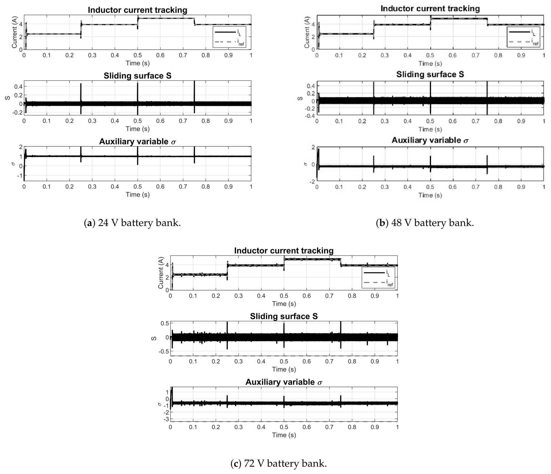
To evaluate the robustness of the controller under external disturbances, irradiance step changes are applied during operation. These steps modify the PV operating point, E, and the simultaneously, exercising the disturbance rejection capability of the controller. The irradiance profile follows the sequence W/m2, with step transitions at regular intervals of 250 ms. This test exercises both the MPPT tracking capability and the inner-loop disturbance rejection.
Figure 7 shows the PV power and
response under irradiance steps for each battery bank. The MPPT algorithm tracks the changing power point, and
adjusts accordingly. The controller maintains regulation during the transitions without exhibiting excessive overshoot or instability.
Figure 8 presents the current tracking and sliding surfaces under the same irradiance profile. At each irradiance step, the MPPT updates
and the ISM controller tracks the new reference within a few switching periods. The sliding variable
S returns to zero after each transient, and
remains within the boundary layer throughout the test, confirming the robustness guarantees of Theorem 1. The quasi-static offset of
adjusts to the new operating current, consistent with (
69).
5.4. Comparison with a Discrete PI Controller
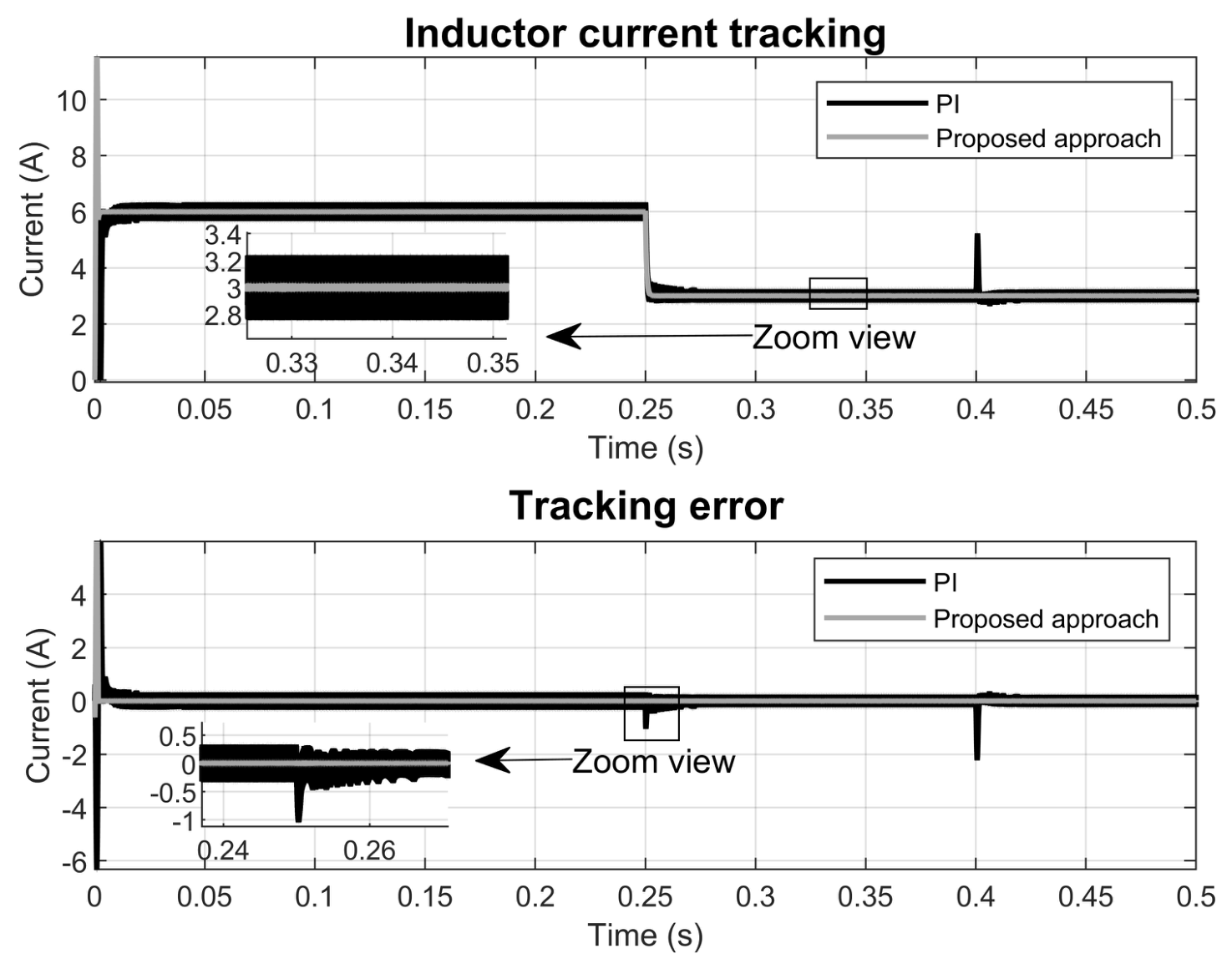
To isolate the effect of the robust compensation from the MPPT dynamics, the proposed ISM controller is compared against a discrete-time PI controller on a simplified test scenario: the PV panel is replaced by a DC voltage source (
V) and the battery bank is replaced by a resistive load (
), so that the capacitor voltage
varies freely with the operating conditions rather than being fixed by the battery. The PI control law is
where
is the current error, with integrator state
,
. The PI gains are selected to match the nominal closed-loop bandwidth of the proposed controller (
s
−1):
Both controllers are tested under the same scenario with two sequential disturbances: a reference step from
A to 3 A at
s, and an input voltage step from
V to 18 V at
s.
Figure 9 shows the inductor current tracking and the tracking error for both controllers. Three differences are observed: (i) the proposed ISM controller exhibits a smaller inductor current ripple in steady state; (ii) the transient response after the reference step is faster for the ISM controller; and (iii) the ISM controller is less sensitive to the input voltage perturbation, recovering the reference with a smaller deviation and shorter settling time. These improvements are attributed to the robust compensation layer, which rejects the time-varying perturbation through the optimal reaching gain, while the PI relies solely on its finite integral bandwidth.
5.5. Analysis Results
To quantify the performance of the proposed controller, the following metrics are evaluated during the steady-state interval after the MPPT algorithm has converged.
The MPPT tracking efficiency measures the fraction of available PV energy that is effectively extracted:
where
is the measured PV power and
is the theoretical maximum power at the given irradiance and temperature.
The current tracking quality is assessed through the root-mean-square (RMS) value of the normalized current error:
Table 5,
Table 6 and
Table 7 summarize the quantitative results for the three battery banks at irradiance levels of 1000, 800, and 500 W/m
2, respectively. In all cases, the battery state of charge is set to 50% and all metrics except the startup convergence time are computed after the P&O algorithm has reached the MPP.
Table 8 compares the proposed ISM controller with the discrete PI controller (
72) using the test scenario of
Section 5.4 (
A,
V,
). Both controllers use the same nominal bandwidth (
s
−1).
Remark 14. The results in Table 5, Table 6 and Table 7 show that the MPPT tracking efficiency remains above a high threshold across all tested conditions. While remains virtually constant across battery voltages, the normalized grows modestly with (from approximately 2% at 24 V to 5% at 72 V), which is attributable to the larger inductor current ripple at higher duty cycles—an inherent characteristic of the power stage, not a degradation of the controller performance. The MPPT startup convergence time stays within a few milliseconds regardless of the battery voltage. 6. Conclusions
This study investigated the selection of reaching gain in discrete-time sliding mode control under multiplicative gain uncertainty. The main contribution is an optimal reaching-gain design that guarantees contraction within the boundary layer for all finite uncertainty ratios. The principal findings are summarized as follows.
The fixed reaching gain used in Misawa’s saturation-based controller was shown to lose contraction within the boundary layer for gain uncertainty ratios as low as 50%. An optimal reaching gain was derived by reformulating the inside-layer dynamics as a stationary relaxation iteration, yielding a worst-case contraction factor strictly less than 1 for all finite uncertainty ratios. This result establishes a unified framework that connects discrete-time sliding mode control with classical iterative methods from numerical linear algebra and convex optimization for reaching-gain design.
The optimal reaching law was incorporated into a discrete-time ISM structure that is specifically designed to eliminate the reaching phase. This approach advances the main contribution in the boost converter application in two key ways. At voltage extremes, where deviates significantly from unity, the direct fixed-gain design diverges within the boundary layer (), while the proposed controller maintains contraction (). Near the nominal voltage (), ISM drift cancellation substantially reduces the effective perturbation compared to the uncompensated drift, thereby narrowing the operating -band well below the worst-case design . Furthermore, a past-step disturbance estimator, regulated by a confidence factor to prevent error amplification, was integrated. When the realized gain is close to the nominal value (), the estimator reduces the quasi-sliding band from to . At the extremes of gain, the improvement diminishes, and the band remains at .
The proposed controller was implemented in a photovoltaic battery charging system using a DC–DC boost converter that serves three battery banks at 24, 48, and 72 V. Simulations with a switching-level model including parasitic elements demonstrated that the inductor current closely tracks the MPPT reference, and the sliding variable converges to a neighborhood of zero. The auxiliary ISM variable remains within the design boundary layer under both constant and time-varying irradiance conditions. Additionally, the steady-state offset of the auxiliary variable was found to scale linearly with the reference current and parasitic resistance, consistent with theoretical predictions. A comparison with a discrete PI controller of matched nominal bandwidth confirmed that the proposed ISM controller achieves smaller inductor current ripple, faster transient response, and reduced sensitivity to input voltage perturbations.
Future research directions include experimental validation of the proposed controller on embedded platforms, extension to multi-input topologies such as interleaved boost converters, and investigation of semi-iterative Chebyshev acceleration strategies for fixed but unknown gain uncertainty.





 ,
,