Review

Review on Power Routing Techniques and Converter Losses Model for VSC-Based Power Router


by
Vinicius Gadelha
1,*,
João Soares-Vila-Luz
2,
Antonio E. Saldaña-González
1 and
Andreas Sumper
1
1
Centre d’Innovació Tecnològica en Convertidors Estàtics i Accionaments (CITCEA-UPC), Departament d’Enginyeria Elèctrica, Universitat Politècnica de Catalunya ETS d’Enginyeria Industrial de Barcelona, Avinguda Diagonal, 647, Pav G, 08028 Barcelona, Spain
2
Instituto Superior Técnico, Universidade de Lisboa, Av. Rovisco Pais 1, 1049-001 Lisbon, Portugal
*
Author to whom correspondence should be addressed.
Electricity 2026, 7(1), 5; https://doi.org/10.3390/electricity7010005
Submission received: 4 November 2025 / Revised: 26 December 2025 / Accepted: 8 January 2026 / Published: 14 January 2026

Abstract

In this work, a comprehensive literature review on power-routing devices is presented, outlining their current design principles and potential uses. Additionally, a comprehensive loss model for Modular Multilevel Converters (MMCs) in the context of power routers (PRs), a promising technology for enhancing flexibility and efficiency in future smart and hybrid AC–DC grids. Despite their potential, large-scale PR deployment is still limited by the lack of accurate and validated loss models. To address this gap, a detailed analytical model based on the Marquardt approach is proposed, capturing both conduction and switching losses in converter-based PRs. The model is validated through analytical comparison and PLECS simulations, showing strong agreement with theoretical and experimental data. Four case studies are presented to assess the effect of parameters such as power factor, active and reactive power, and the number of submodules on the overall converter losses. The results demonstrate that PR efficiency improves with optimized converter design and proper parameter selection.

1. Introduction

The power system is undergoing a profound transformation driven by the increasing penetration of Renewable Energy Sources (RESs), the emergence of Distributed Energy Resources (DERs), and the growing demand for clean and reliable electricity. This is crucial to support the future of energy transition, which will involve the proliferation of RES, electric transport, and power electronics. In 2023, nearly 14 million new Electric Vehicles (EVs) were registered globally, with the total number on the roads reaching 40 million [1].
To create the RES-based flexible and reliant power grid of the future, is necessary to overcome several challenges [2]. The integration of different DERs requires a huge effort from grid operators in terms of creating advanced metering devices and communication and control strategies that are capable of managing bi-directional and stochastic power flows. This will also lead to large volumes of data being generated and managed, which is already a reality in any country that wants to develop end-user-centred policies such as demand response and flexibility trading. This trending research focus has gained a lot of interest, especially within the academic community, with several EU-funded projects investigating the use of big data in electricity markets [3], flexibility trading mechanisms [4], and open data spaces [5]. Furthermore, cybersecurity issues become increasingly prominent as more smart appliances are connected to the power system. Similarly, privacy concerns arise with the use of end-user data, which is becoming increasingly accessible due to the rollout of smart meters [6]. When expanding to more broad concepts such as the Internet of Things and Smart Cities, the scale of the cybersecurity problem becomes even more complex. Regulatory entities, together with academia and interested bodies, face the important task of promoting interoperability by promoting the standardisation of protocols while setting constraints to reduce the threat of digital intrusion [7].
Another challenging aspect that future grids will face is the loss of system inertia due to the massive presence of converter-based generators, which will replace traditional power plants with high storage capacities. The energy transition will require services such as frequency containment reserve or the provision of synthetic inertia in order for the system to operate in a robust and secure manner [8]. In this context, Virtual Power Plants (VPPs) with suitably designed feedback control systems can harness the fast dynamic response of low-inertia generators to complement the transient response of conventional generators [9]. The widespread deployment of RESs is becoming increasingly challenging due to the high number of DERs being integrated at the distribution-system level. New planning strategies capable of accounting for these emerging aspects are becoming increasingly important [10], especially given the rapid deployment of EV chargers [11,12]. While these resources have the potential to alleviate local congestion, address voltage deviations, and unlock the benefits of local flexibility, their overall impact on the transmission system remains uncertain [13]. In this scenario, cooperation between distribution system operators (DSOs) and transmission system operators (TSOs) will also play a crucial role in enabling the full potential of the future grid.
Finally, the increasing prevalence of DC technologies such as solar PV systems, battery energy storage systems, and EVs highlights the current trend towards hybrid AC-DC networks. Worldwide, various projects involving hybrid AC-DC grids have been completed or are ongoing, indicating the significant attention they will attract in the coming decades [14]. All of these topics pose remarkable challenges, summarized in Figure 1, that grid operations and industry partners must face, although they also have the potential to achieve a sustainable and clean future power system. This paper focuses on a novel grid design based on power electronics that could help to solve three of the challenges presented: unlocking energy flexibility, integrating DERs, and incorporating DC systems.

1.1. The Role of Power Router in the Energy Transition

It is well accepted in the literature that the pathway towards a 100% RES-based electric power system will be achieved through power electronics [15]. As more RESs are added into power systems, the future grid will have many more inverter-based generators and be much more widely distributed than the current power system, which is dominated by central-station synchronous generators. The wide spread of power electronics in the power system, as well as the constant technological advancements in storage systems, synthetic inertia, and converter efficiency are essential for solving the challenges presented in Figure 1. This would lead to the next stage of evolution of power systems, which is often called the energy internet: a new energy-utilisation system which integrates renewable energy, distributed power plants, hydrogen, storage technologies, and electric vehicles with Internet technology [16].
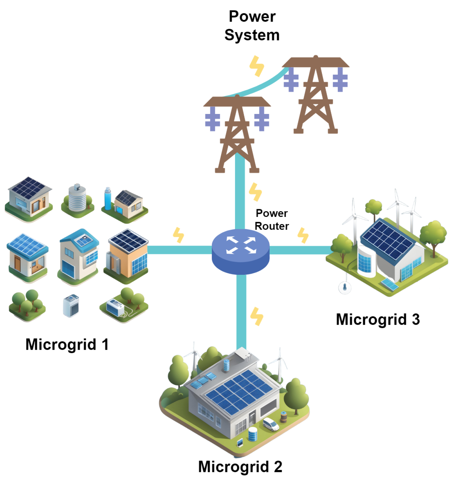
It was within this context that the initial concepts of a PR were conceived in 2010. The original PR design aimed to achieve the proposed principle of adding information to electric power transmission and distributing power through packages according to an ‘electronic tagging’ system [17]. The idea of routing electricity to designated nodes, similarly to the methods used in internet communication, rather than allowing it to flow indiscriminately through the wires has opened up new possibilities for grid planners and operators. These concepts, combined with the increasing interest in decentralising the power system with microgrids and VPPs, generated novel power grid designs [18,19,20,21]. As an example, consider the following scenario depicted in Figure 2, in which three different microgrids are interfaced by a PR that controls the energy exchange between them as well as the energy exchanged with the power system. In a traditional network, there is no direct control over how much power is exchanged between microgrids. For instance, if microgrid 1 requires more power, the PR will be able to choose which source the power will come from, something that is impossible to do in a traditional network. In a future scenario in which internet communication is even more prominent and many users have access to some sort of power source (PVs, batteries, etc.), exchanging electricity through bilateral contracts or peer-to-peer trading will demand the network to be capable of performing power routing [22,23]. On a bigger scale, PRs will also play a pivotal role in the integration between DC and AC networks. In the UK, the deployment of offshore wind power plants is expected to increase in the next few years, from a capacity of 11.3 GW in 2022 to 50 GW by the end of 2030 [24]. PRs could help enhance the current network design and provide a seamless integration between different parts of the UK’s transmission grid, either AC or DC, at different voltage levels.

1.2. Motivation and Contributions

The main aim of this paper is to contribute to the advancement of PR technology as a key enabler of future power grids. Despite their potential to support the energy transition, the large-scale deployment of PRs remains limited by several open research challenges. First, the diversity of terminology and design concepts makes it difficult to clearly define what constitutes a power router and to identify its intended applications. The existing literature reviews often focus on specific design features or topologies, thereby failing to provide a comprehensive perspective of the field. This paper addresses this gap by presenting a broad and structured review of the different PR design concepts reported in the literature, analysing their intended applications and key characteristics. Additionally, there is a lack of accurate and reliable loss models for PRs. Since PRs rely on power electronics to control and route electricity flows, their efficiency directly depends on converter performance. However, most of the existing works focus either on high-level functionalities or on conceptual demonstrations, without providing detailed analyses of the converter losses. Without a validated converter loss model, it is difficult to assess the real efficiency, scalability, and feasibility of PR-based grid architectures.
Moreover, as new network designs integrate PRs into the broader context of smart grids and hybrid AC–DC grids at an increasing rate, the need for accurate efficiency assessments becomes even more critical. Studying how converter parameters and operating conditions affect PR efficiency is therefore essential to guide both academic research and industry adoption. To address these gaps, the main contributions of this paper are as follows:
  • To provide a comprehensive and structured literature review of PR devices, outlining their design principles, current state of the art, and potential uses.
  • To establish a comparison between each of the PR designs found in the literature and analyse trends in their adoption throughout the years.
  • To support future research on PR devices by developing an easy-to-implement loss model for PRs, grounded in the Marquardt approach, capturing switching and conduction losses for accurate efficiency estimation under varying operating conditions.
  • To assess, through four case studies, the impact of parameters such as the number of submodules (SMs), power factor, and loading conditions on overall PR losses, offering practical insights for optimal design and operation.
This paper is structured as follows: Section 1 introduces the research background, objectives, and key questions. Section 2 reviews the existing literature and provides a comparative overview and describes the state of the art of different PR concepts. Section 3 describes the converter loss model developed and implemented in this work. Section 4 presents and discusses the results through four case studies, each analysing a specific aspect of converter losses and validated against reference studies or simulation results. Finally, Section 5 summarizes the main findings and presents the conclusions.

2. State of the Art on Power Router Concepts

Power electronics play an important role in the modernisation of power systems and supporting the necessary RES and EV integration [2,25]. Central to this transition are PRs, devices that facilitate the flexible and efficient management of electricity, representing the importance of power electronics in driving the shift towards sustainable energy. As a general concept, a PR is a device composed of multiple ports that provides a seamless interface of different elements of a power grid by controlling, also called routing, power between ports [18,26,27]. PR technology was first envisioned as a mechanism for the transition to the energy internet, in which the bi-directional communication among the producers, consumers, and market agents are key to unlocking peer-to-peer energy-trading markets [23].
This broad definition comprises the many applications these devices have, which have been the subject of study in recent studies. The name given to such devices mostly depends on the purpose of the research and the interfaced elements. For example, the authors of [28] defined it as a ‘dynamic energy router,’ as it focuses on managing energy storage and interfacing the usage of different types of energy resources such as fuel cells and super-capacitors. More recently, ref. [29] proposed a new electrical design for what authors named an ‘electric energy router’, which could increase the amount of active and reactive power flow by up to 200% and 120%, respectively. Ref. [30] analysed the power-routing capabilities of interconnected photovoltaic (PV), storage systems and AC loads, naming it the ‘DC microgrid’. Ref. [31] describes an energy-sharing structure for microgrids using ‘energy routers’ and proposes a model of battery operation for improving prosumers’ revenue in a peer-to-peer energy-trading market. In these applications, the PR, also named the energy router, operates similarly to an energy-management system, providing efficient control and operation of assets such as PVs, battery energy storage systems, EVs, and AC/DC loads [32,33,34,35,36]. Ref. [37] provides a deep overview of the challenges and potential benefits of the transition to energy internet, in which ‘energy routers’ are used to provide plug-and-play capabilities and communication between energy cells. The energy cells consist of a local electric generator, storage devices, dispatchable/non-dispatchable electric loads, and electric vehicles that are able to trade energy through a network infrastructure. Recent studies have focused on the transition between local applications and energy internet. For instance, ref. [38] provides the basic architecture of an energy router interconnection system, in which these devices are used for the local control of assets as well as intelligent grid interconnection. The authors of [39,40] proposed a similar design of a multiport energy router capable of controlling power flows and managing assets for AC or DC applications.
Other studies extend the use of PR technology beyond an intelligent energy management system. In [41,42,43], PRs are utilised by coupling direct AC converters to three-winding transformers in order to reduce congestion and increase system reliability. In other works, these devices are called controllable network transformers and combine load tap changers with power converters [44]. In [45], this concept is expanded, offering decoupled control of active and reactive power flows, and it is also compared to other solutions such as unified power-flow controllers. In urban transport, ref. [46] developed a hierarchical control strategy using PRs to leverage the power used in urban train operation to enhance the voltage regulation of a common DC bus. Similarly, ref. [47] used a PR to control and exchange power among the grid, different DC sources, and EVs moving on a mounted coil surface lane. Another field of application of PRs is interconnecting radial grids creating a semi-meshed configuration. In this application, the PR is named soft open point (SOP) and is installed in strategically normally open points in electrical power distribution networks to provide services such as active and reactive power control, as well as voltage regulation [48]. The literature on the applicability of SOPs in power systems is broad [49,50,51]. Ref. [52] provides a cost–benefit analysis of the services provided by SOPs in distribution networks. Ref. [53] developed new operation constraints for the use of SOPs and prevented unfeasible states using a Distribution System Restoration (DSR) model. Recent studies combined SOPs with multi-terminal switches to increase power transfer performance, reducing the necessary converter capacity by up to 24% [54]. Ref. [55] uses a similar concept of multi-terminal SOPs to propose an optimisation using second-order cone programming for feeder load balancing. In contrast, ref. [56] focuses on the optimal placing of these devices to increase the efficiency of distribution networks. Other studies analyse different topologies, such as the series-shunt multi-port SOP proposed by [57].
The interconnection of multiple PRs leads to the concept of a digital power grid defined in [58]. In [59,60,61,62,63], the PR was further explored, presenting new network architectures, namely a ‘controlled-delivery power grid’ [60] and a ‘pulsed power network’ [62], which were experimentally tested in [61,63]. Then, the classical optimal power-flow formulations for active distribution networks were extended to include PR devices in [64]. A power-dispatching protocol for a packetised-power network is presented in [65], in which multiple electric-energy routers control the power flow, and the electric energy is packetised and transmitted from a sender to a receiver [65]. In [66], this concept is further elaborated upon using PRs in a combination of circuit-switching and power-dispatching strategies, promoting the initial notions of future smart grids. Similar PR definitions are presented in [63,67,68], where data-routing strategies, typically used in telecommunications, are applied to power distribution systems and home applications. Other applications include using PR to not only control power dispatch in microgrids, but also to enable islanding operation [69,70].
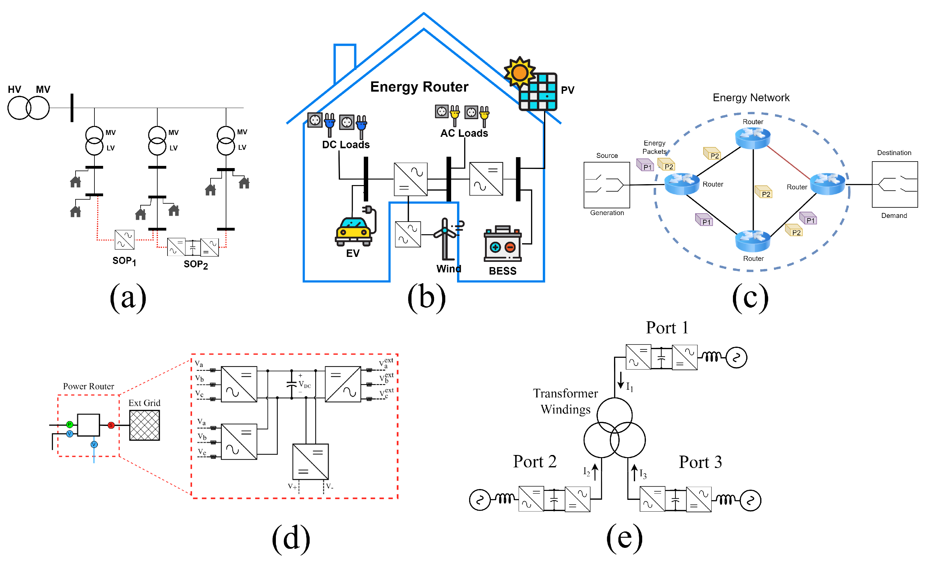
Ref. [71] provides a review of the different PR technologies applied to the energy internet. Three categories are suggested according to the technology the PRs are based on—a solid-state transformer, multi-port converter, or power-line communication. Similarly, the authors of [72] provide a review of PRs, named multi-port converters, focusing on comparing various converter topologies for both isolated and non-isolated configurations in the context of solar and storage integration. Each of these reviews provides valuable insights into the applicability of PRs. However, they do not address unconventional designs such as the power packet router or application-specific devices such as SOPs. Encompassing all these categories, Figure 3 illustrates representative examples of the five PR design types identified in the literature. Additionally, a comprehensive overview from 25 different studies in the literature is presented in Table 1. Each reference is classified based on five categories. The first category is the type of PR design used in the study, based on the concepts presented in Figure 3. Then, the references are organized based on whether the study considers HVDC lines or allows the power flow control of AC lines. The control strategy is classified as either centralised, meaning that the control reference points come from a centralised source, or distributed, meaning that each power electronic device can operate independently without relying on external references to guarantee the system’s operation. These works are also distinguished based on the source of control reference given to the PR, i.e., whether it comes from optimisation problems, routing algorithms, Probabilistic Power Flows (PPFs) or droop controls. Finally, a brief description of the scope of each study is provided in order to contextualize and showcase their key elements. Despite the differences among all these concepts in terms of scope and application, the PR is fundamentally viewed as a power electronic device that is able to reinforce, support, or improve the grid’s behaviour by providing the capacity to redirect the power flows as desired.

Comparison, Trends, and Gaps

Considering all the references discussed above, together with the comparative analysis presented in Table 1, important characteristics and key contributions can be identified. First, it is important to note that a direct comparison between the different concepts and the work underlying them has limited value, as their scope and objectives differ substantially. Instead, this review proposes a characteristic-based approach that does not aim to identify the single ’best’ design or topology, but rather to support decision-making by clarifying which design is most suitable for a given application.
Regarding integration capability, types (b) and (d) stand out, offering strong potential for integrating local assets within a microgrid as well as for interfacing AC and DC lines. Types (a) and (d) demonstrate high scalability and modularity due to their ability to increase the number of ports with relative ease. In contrast, type (b) is more appropriate for local applications and does not inherently support AC–DC interconnection. Type (e) provides limited scalability, as the number of ports is restricted by the available transformer windings. However, from a cost and implementation perspective, type (e) offers clear advantages because it can leverage existing three-winding transformers. Finally, the main strength of type (c) lies in its novelty and potential, as it enables the integration of advanced communication and control concepts that may significantly enhance future power-system flexibility and interoperability.
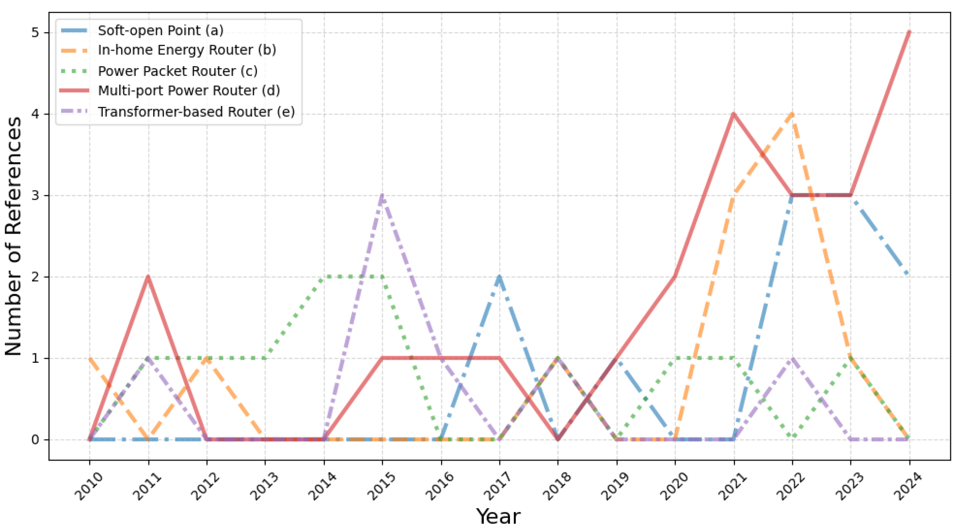
To further enrich the analysis, it is important to consider the temporal context in which each design concept, and the associated literature, has emerged. Figure 4 illustrates the number of publications related to each design type over the years. In addition to the key references highlighted in Table 1, all studies cited in this section were included, resulting in a total of 63 publications analysed. Examining the type (c) design, the power packet router, reveals that research activity peaked between 2013 and 2016. This rise aligns with the early developments of smart-grid concepts, which provided fertile ground for communication-driven energy-routing approaches. A similar pattern can be observed for the transformer-based router (type (e)), although interest in both concepts has declined in recent years. This trend is likely due to the practical challenges associated with implementing type (c) in real systems, and the inherent limitations in scalability and functional benefits offered by type (e). In contrast, a trending shift towards power electronics-based designs can be identified. Types (a), (b), and (d) have experienced substantial growth in the literature since 2020, largely driven by the increasing need for system flexibility and the expanding role of power electronics in enabling advanced grid support functionalities.
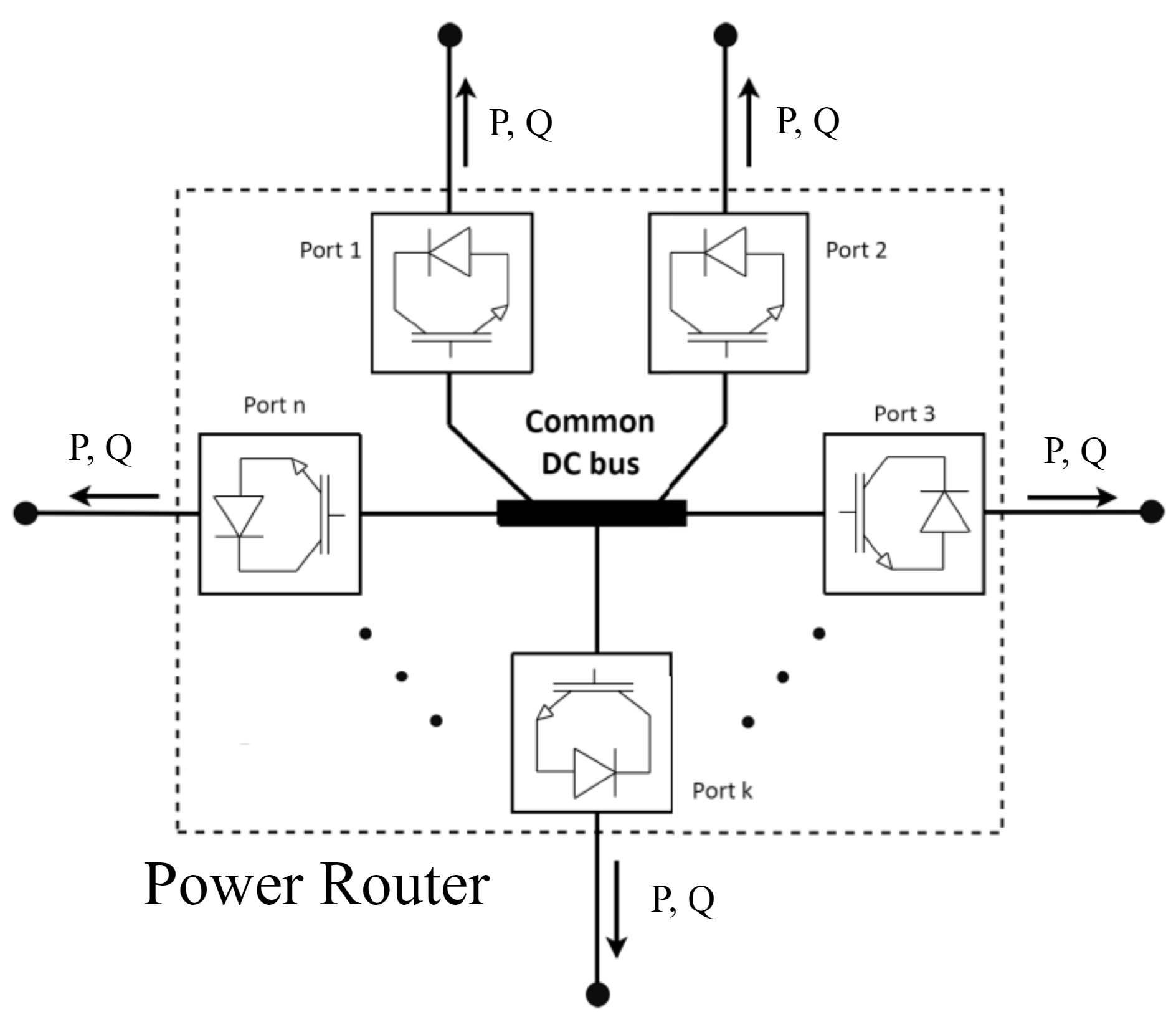
The analysis of the reviewed works reveals an important gap: the majority of studies emphasize conceptual frameworks, control strategies, and high-level functionalities without providing a detailed assessment of converter losses under varying operational conditions. This gap limits the ability to evaluate PR efficiency, scalability, and practical feasibility, as the internal losses of the converters forming the PR are frequently oversimplified or overlooked. To address this, this paper introduces an easy-to-implement converter loss model that is designed to support future research on PR technology. Given the growing interest in multiport-converter-based PRs and their strong potential for diverse applications, this topology was selected for the present study. This PR concept was proposed and experimentally validated by [26], and consists of coupling a set of voltage source converters (VSCs) to a common DC bus, in which each converter functions as a different input or output port. The design is further detailed in Figure 5, in which a generic n-port PR is depicted with its common DC bus and VSC converters. For consistency and easier understanding, throughout this paper, the VSCs that compose a PR will be addressed as ports. The following sections present a detailed analysis of the losses within these devices. Furthermore, different use-case studies are performed to examine the influence of key parameters such as the number of submodules, power factor, and active/reactive power flow.

3. Power Loss Model Inside a VSC-Based PR

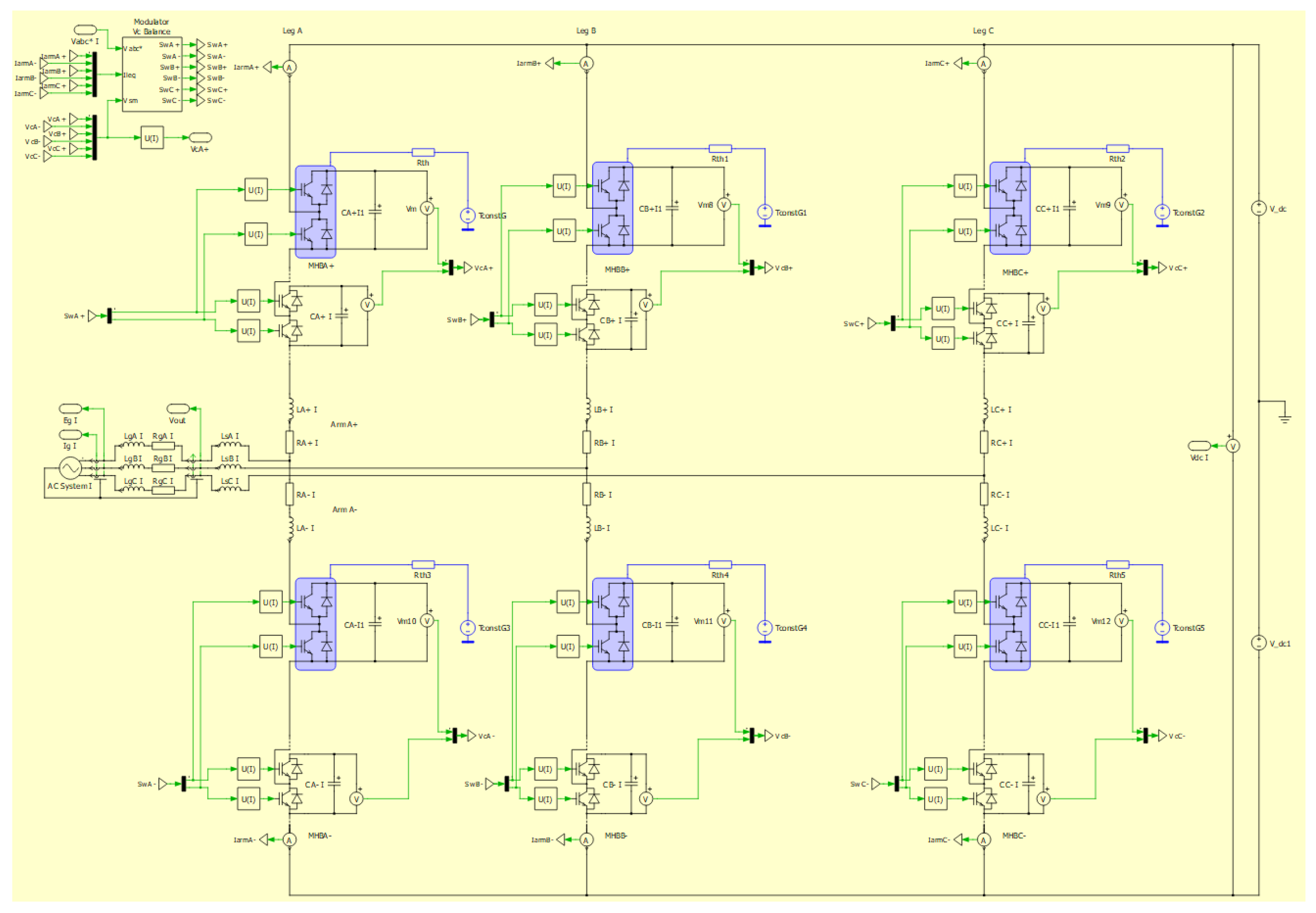
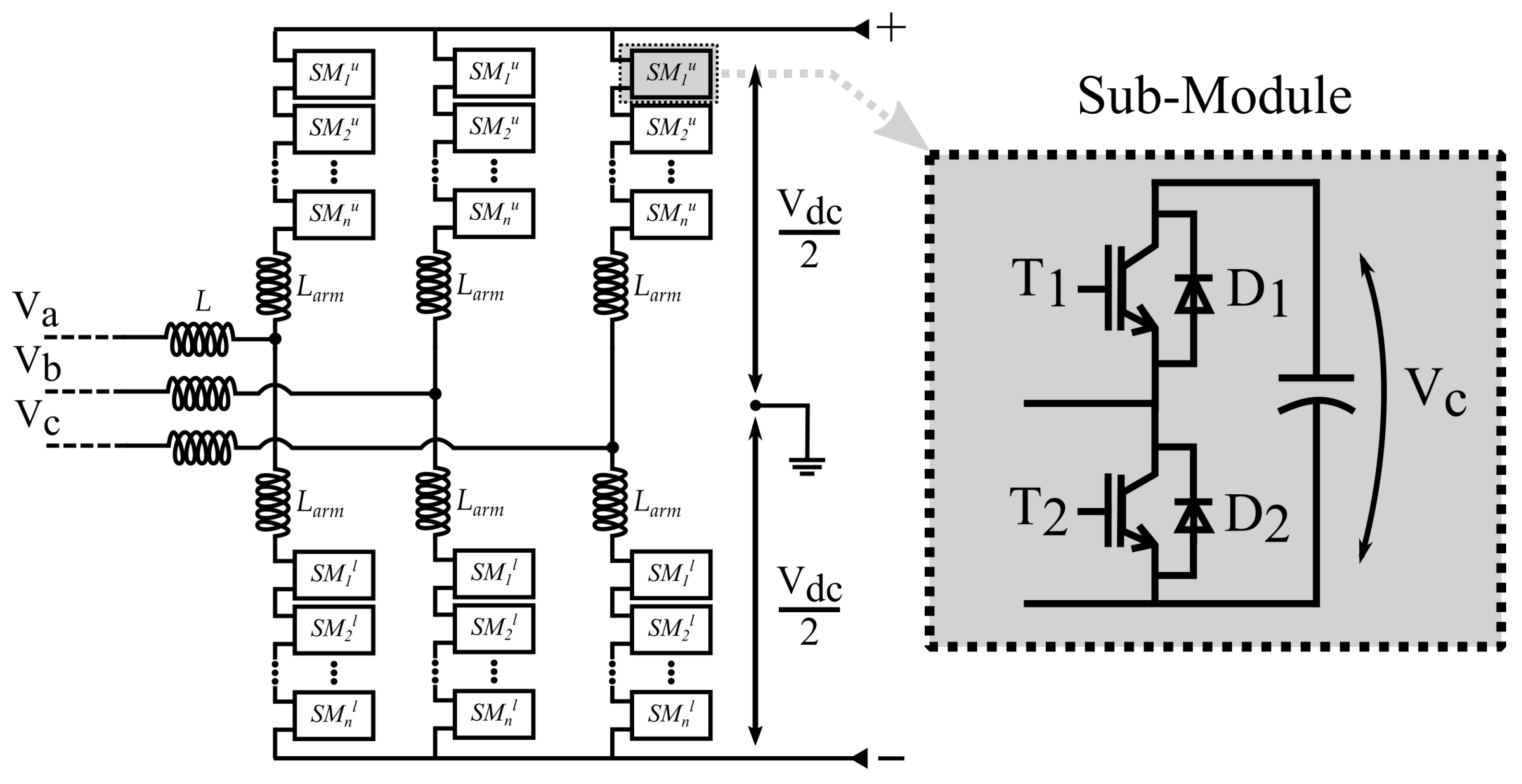
Having established the PR design adopted in this study, the next step is to define a suitable loss model for its converter ports, allowing for an accurate assessment of device efficiency under different operating conditions. Before introducing the model, some assumptions and clarifications are necessary: The proposed model focuses on an AC Power Router, initially formulated for a single-phase configuration and subsequently scaled to represent a three-phase system. By comparing different converter topologies and following the design principles outlined in [18,26], the Modular Multilevel Converter (MMC) was selected due to its inherent modularity and scalability. Each arm is composed of half-bridge submodules, which were chosen for their structural simplicity and widespread use in power electronic applications. Although several factors contribute to total converter losses, the most significant components are the Insulated Gate Bipolar Transistors (IGBTs) and their associated diodes, as highlighted in [81,82]. The electrical scheme of a PR port is shown in Figure 6, complementing the internal structure of the PR depicted in Figure 5.

3.1. General Model

3.1.1. Conduction Losses

Conduction losses occur when the IGBT or the freewheeling diode is in the on-state and conducting current. The instantaneous power dissipation during conduction is given by the product of the on-state voltage and current, and the average conduction power loss over a switching period T can be expressed as follows:
P c o n d ( I G B T ) = 1 T 0 T [ V C E ( t ) I C E ( t ) ] d t
A first-order approximation can be obtained by multiplying the IGBT’s on-state voltage drop by the average current. To derive an equation that can be directly related to data-sheet parameters, the above expression is often linearised as follows:
P c o n d ( I G B T ) = V C E 0 i + R 0 i 2
P c o n d ( D i o d e ) = V D 0 i + R D 0 i 2
Here, V C E 0 and R 0 represent the on-state threshold voltage and on-state resistance of the IGBT, respectively, while V D 0 and R D 0 are the corresponding parameters for the diode. These values can be obtained from the on-state parameters graph that is usually present in the device data sheet. The current i represents the average conduction current, which requires careful consideration, as accurately modelling its waveform and mean value is essential for precise loss estimation.

3.1.2. Switching Losses

Switching losses can represent a major portion of the total semiconductor losses and are highly dependent on the converter’s switching frequency. These losses occur during the transitions between the on-state and the off-state, when both the current through and the voltage across the device are non-zero, resulting in significant instantaneous power dissipation. The total switching power losses can be expressed as follows:
P S w i t c h ( I G B T ) = ( E O n + E O f f ) f s w i t c h
P S w i t c h ( D i o d e ) = E R e c f s w i t c h
where E O n and E O f f are the turn-on and turn-off energy losses of the IGBT, E R e c is the reverse recovery energy of the diode, and f s w i t c h is the switching frequency. To adapt these switching losses to the specific operating conditions of a given application, the nominal values must be normalized using the ratios of actual to nominal current and voltage, as expressed by
P S w i t c h ( I G B T ) = i I N O M ( E O n + E O f f ) f s w i t c h π V S M V N O M
P S w i t c h ( D i o d e ) = E R e c f s w i t c h π i I N O M V S M V N O M
Here, i represents the instantaneous current, I N O M represents the nominal current passing through the semiconductors, and V S M represents the nominal voltage across the semiconductor device. It is important to note that the semiconductor parameters E O n , E O f f , E R e c , V C E 0 and V D 0 , are typically provided in device data sheets as current-dependent curves. For modelling purposes, these curves can be accurately captured using a third-order polynomial approximation of the form of a I c 3 + b I c 2 + c I c + d as described in [83]. This allows the parameters to be evaluated consistently across different operating conditions.

3.1.3. Total Losses

The total losses of a single PR port, represented by an MMC converter, are obtained by summing its conduction and switching-loss components. It is important to note that additional effects, such as inductor losses and auxiliary cooling power, also contribute to the overall power dissipation. However, their influence is generally secondary compared to semiconductor-related losses [84]. Given that the objective of this work is to develop a simple, scalable, and general loss model for PR applications, these secondary effects are neglected. Consequently, the total losses can be expressed as shown in Equation (8):
P T o t a l = P c o n d ( I G B T ) + P c o n d ( D i o d e ) + P S w i t c h ( I G B T ) + P S w i t c h ( D i o d e )
Several models have been proposed to estimate power losses in VSCs, particularly for the MMC topology. The work in [85] addresses inaccuracies in conventional valve loss estimation methods arising from uncertain submodule switching behaviour. The authors of [86] focus on evaluating valve losses in MMC-HVDC systems and provide valuable insights into how converter losses evolve with variations in power factor—an aspect that is directly relevant to this work. Another important contribution is presented in [83], which highlights how the choice of submodule-sorting algorithm (focusing on conventional, improved, or reduced switching frequency (RSF)) strongly affects total losses, with RSF achieving the lowest dissipation and most balanced distribution. Finally, ref. [87] investigates MMC designs with reduced safety margins while ensuring operational reliability. These studies provide accurate models of power losses and define arm currents precisely; however, they often rely on detailed switching logic rather than averaged current models, which significantly increases computational complexity.

3.2. Marquardt Model

The work presented in [88] introduces a comprehensive loss model for HVDC converters, with particular emphasis on the MMC topology. This model offers a systematic approach for evaluating semiconductor conduction and switching losses based on key design and operational parameters, which are detailed in the following subsections. The main advantages and limitations of the Marquardt model are discussed in [89]. Its advantages include excellent scalability with the number of submodules, the use of analytical expressions for estimating power losses, and high computational efficiency, which make it suitable for large-scale system simulations. However, the model also has limitations: it assumes that semiconductors operate at their maximum junction temperature, neglects inductor and cooling system losses, and assumes a linear relationship between switching losses and current. Moreover, as stated in [90], this is an average model that may underestimate total converter losses under highly dynamic or low-modulation operating regimes. To address these limitations, different modelling techniques have been proposed in the literature. The authors of [91] provide a detailed analysis of MMC losses and the second-order harmonic circulating current that typically flows in the converter arms, while also proposing a loss optimisation control scheme that injects a compensating current. In contrast, the authors of [92] analyzed the effects of SM capacitor voltage deviations, proposing a new method to evaluate the switching frequency and switching losses of MMC.
Since the goal of this paper is to provide an easy-to-implement loss model for VSC-based PRs, the Marquardt model offers a good balance between physical accuracy and modelling simplicity, providing a good level of detail and accuracy while maintaining a simple analytical structure that enables scalability and integration into broader system studies. Moreover, its analytical nature facilitates the implementation of parametric analyses such as the evaluation of the influence of power factor, switching frequency, and SM number on total losses while keeping computational demands manageable.

3.2.1. Conduction Losses in the Marquardt Model

In the study of the losses of the HB-MMC, we need to define several additional parameters as shown in the formulas presented in Equation (9). The first parameter, m, represents the normalized ratio of the AC current | I a c ¯ | to the DC current | I d c ¯ | . The second parameter, k, represents the relative amplitude of the AC voltage that the converter controls, also known as the “modulation index”. The third parameter, x, represents the normalized sizing of the storage capacitors ( C 0 ) of the submodules. The fourth parameter, b, represents the relative amplitude of the DC-Bus-voltage V d c that the converter controls. A common nominal value for this “DC-side modulation index” is b = 0.5. Finally, I e q * is the equivalent on-state current.
The parameters m , x , b , k , I e q * are defined as follows:
m = 3 π | I a c ¯ | I ¯ d c , | m | > 2 x = ( 1 m 2 ) 3 2 , 0.65 < x < 1 b = V d c 2 n V ¯ c , 0 < b < 1 k = 2 m cos ( φ ) , 0 < k < 1 I e q , P , N * = I ¯ d c 3 ( m ± 1 ) π 4
where V C is the average capacitor voltage and n is the number of SMs per arm. Subscript P corresponds to T 2 and D 1 while subscript N corresponds to elements T 1 and D 2 of the SM.
With the parameters previously defined, the average currents flowing through the semiconductors of each submodule can be determined as shown in Equation (10). Assuming that the real power is evenly distributed among the three phases of the converter and that the phase voltages remain balanced, all submodules will operate under identical loading conditions. Consequently, each converter arm conducts a DC current of I d c 3 and an AC current of I a c 2 . According to the Marquardt model, the resulting equivalent current in each semiconductor can therefore be expressed by the following relations:
i ¯ T 1 , D 1 = 1 4 b x | I a c ¯ | i ¯ T 2 , D 2 = m 4 ( 1 b x ) | I a c ¯ | ± 1 6 I ¯ d c ( 1 ± 1 3 m )
Here, i ¯ T 1 , D 1 represents the average current flowing through the IGBT and the diode of the first switching pair, while i ¯ T 2 , D 2 corresponds to the current through the second pair. Once the average and equivalent currents have been determined, these parameters can be substituted into Equations (2) and (3) to obtain the final analytical expressions for the conduction losses of each semiconductor device.
P T 1 , T 2 = ( V C E 0 + R 0 I e q * ) i ¯ P D 1 , D 2 = ( V D o + R D o I e q * ) i ¯

3.2.2. Switching Losses in the Marquardt Model

To accurately estimate the switching losses of semiconductor devices, it is essential to have either experimentally measured data or reliable specifications provided in the manufacturer’s data sheets. Although switching losses cannot be determined with absolute precision, dependable estimates can be obtained by using the known values of turn-on loss, turn-off loss, and reverse recovery loss specified by the manufacturer. These parameters are typically provided for a defined reference voltage, reference current, and maximum junction temperature. Once these reference conditions have been identified, Equations (6) and (7) can be applied to calculate the switching losses in the power semiconductors. For this type of loss, the corresponding average current is defined as follows:
i ¯ a v , P , N = 1 6 I ¯ d c ( 2 m π ± 1 + 1 3 m )
where, once again, subscript P corresponds to T 2 and D 1 , while subscript N corresponds to T 1 and D 2 of the SM. The final equation for the switching losses is given by
P T 1 , T 2 = f c ( E o n + E o f f ) V ¯ C i ¯ a v V N O M I N O M P D 1 , D 2 = f c E r e c V ¯ C i ¯ a v V N O M I N O M

4. Results and Discussion

To evaluate the performance and validity of the proposed loss model, four case studies are presented, assessing different operating and design conditions while comparing the results with established references in the literature. The first case study focuses on validating the model’s accuracy by reproducing the results obtained in the original Marquardt model [88]. The second and third case studies analyse the impact of the active, reactive power as well as the power factor in the converter losses. Finally, the fourth case study utilizes a PLECS simulation to investigate the influence of key design variables, including the number of submodules (SMs), on the efficiency and behaviour of the converter losses. The following subsections describe each case study in detail, presenting the obtained results and discussing their implications for the modelling and design of Power Routers.

4.1. Case Study 1—Model Accuracy

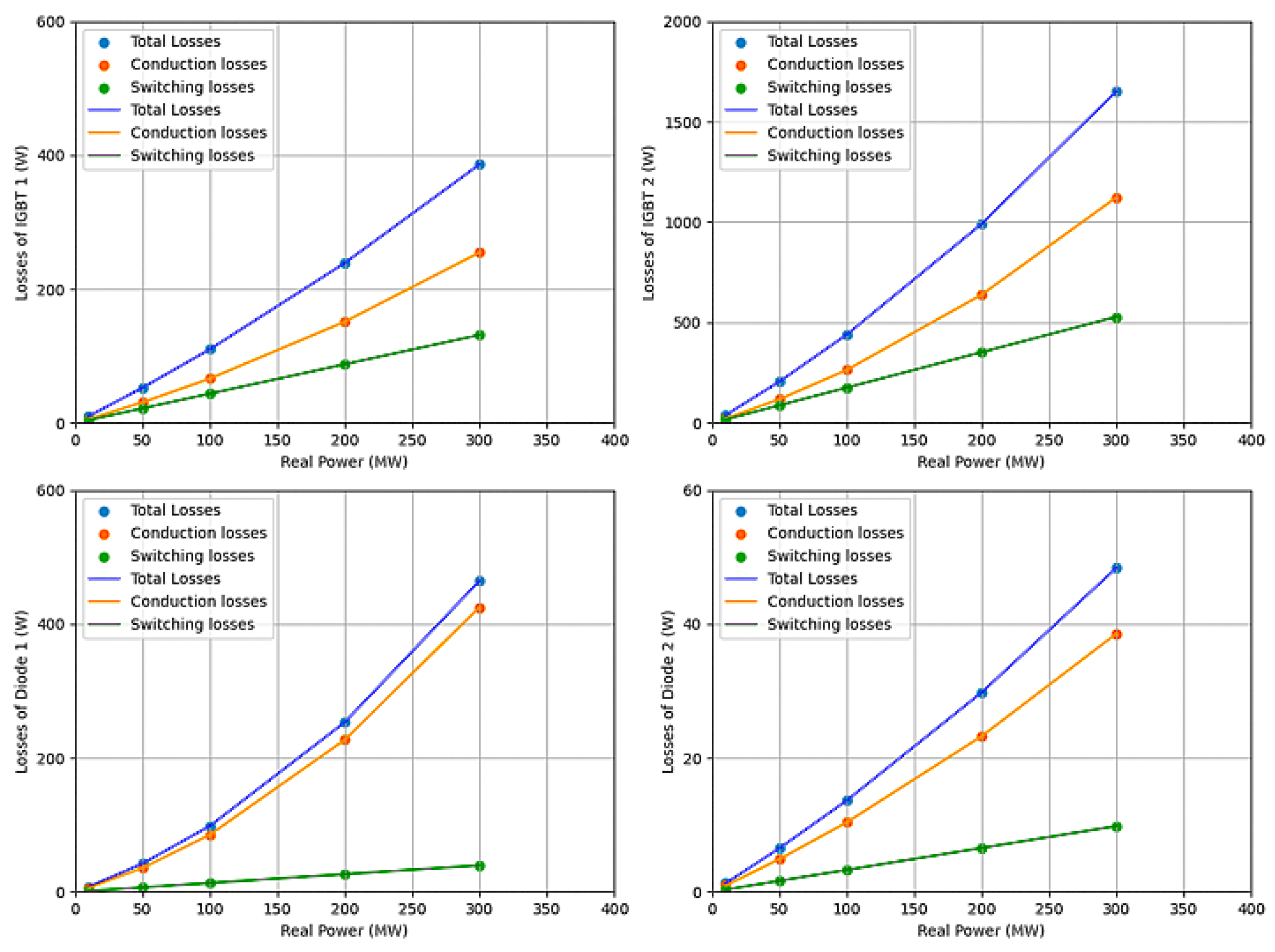
This case study focused on validating the accuracy of the developed model implementation. To achieve this, the case study presented in the original paper that introduced the Marquardt model [88] was replicated under identical conditions. The proposed model was executed using the same parameters and operating conditions as in the original study, enabling a direct, one-to-one comparison between the two sets of results. The outcomes obtained from our implementation are presented in Figure 7, giving very accurate results.
By comparing the results, some conclusions can be highlighted. Conduction losses, caused by the internal resistance of the semiconductor material, remain low at small power outputs but increase quadratically with current as real power rises. Switching losses, which occur during transitions between the ON and OFF states of semiconductor devices, show a similar growth pattern due to there being higher energy dissipation per switching event as the current and voltage increase. Consequently, total losses, which comprises both conduction and switching components, increases with the active power flowing through the converter, indicating that a gradual reduction in converter efficiency occurs at higher power levels. Additionally, when operating with a positive power factor (inverter mode, power flowing from AC to DC), IGBT 2 conducts a larger current, whereas for a negative power factor (rectifier mode, power flowing from DC to AC), IGBT 1 and Diode 1 carry higher currents due to the reversal of current flow paths. Overall, the comparison between the reference and simulated results demonstrates that the developed model accurately reproduces the expected loss behaviour under different operating conditions, confirming its validity and reliability.

4.2. Case Study 2—Impact of Active and Reactive Power

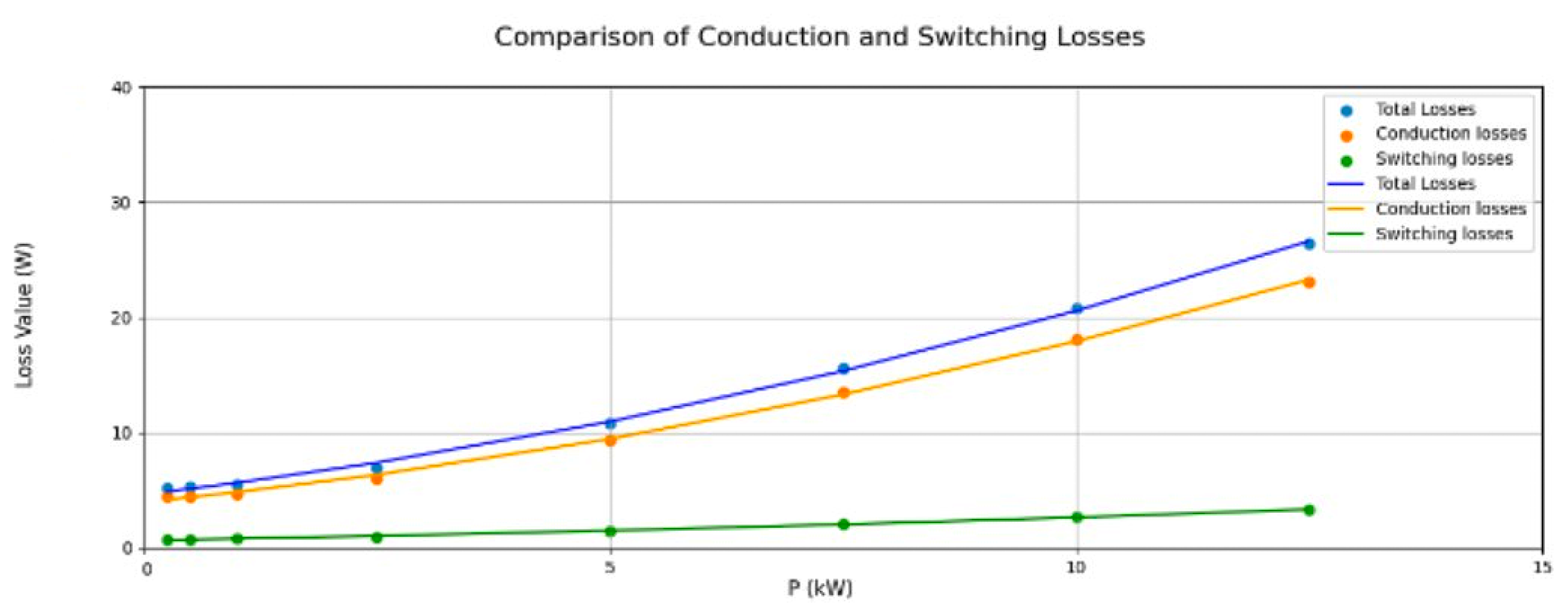
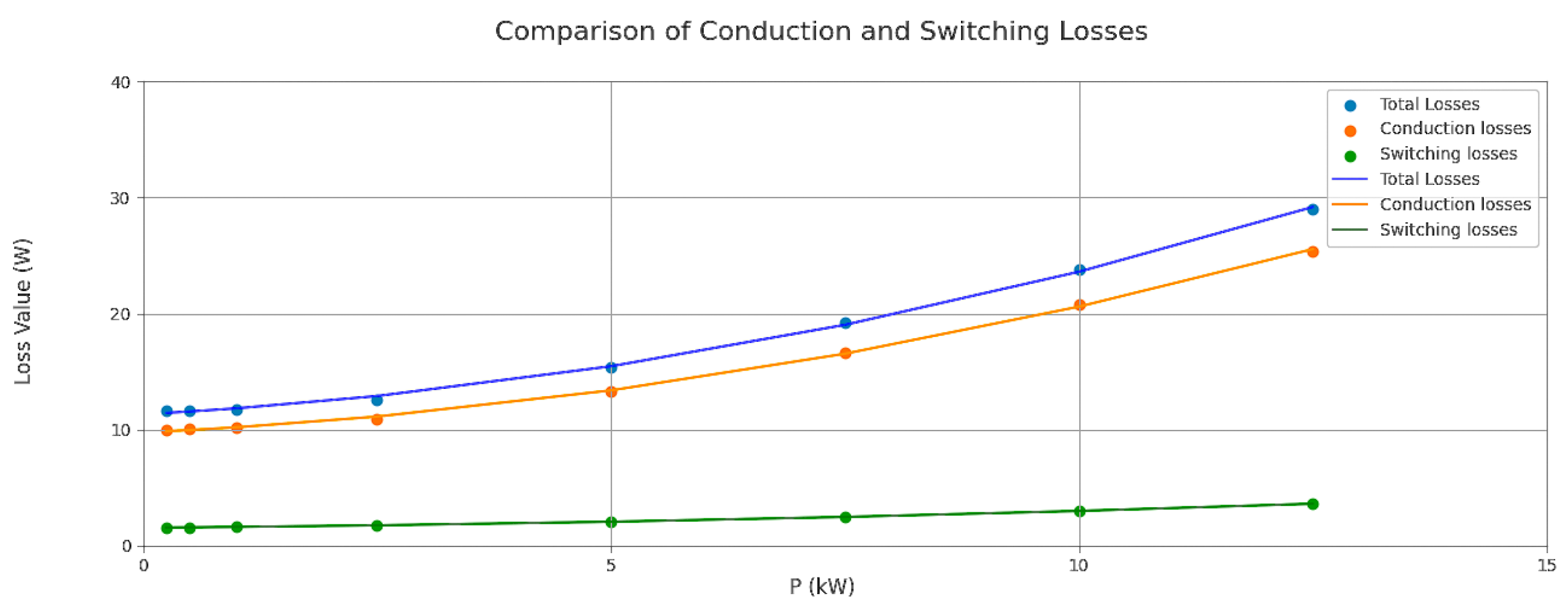
The second case study presents a comparative analysis between the proposed model and the one developed in [83], with the aim of evaluating the behaviour of the proposed approach under different operating conditions. Similar to the previous case study, all parameters were kept constant except for the power level, which was varied to observe its influence on total converter losses. However, two separate cases were analysed, each with a fixed but distinct value of reactive power. The results were obtained using the same parameters defined in [83], together with data from the ABB 5SNA-1200G450350 IGBT data sheet. The corresponding results are shown in Figure 8 and Figure 9 for the proposed model for 3.5 and 6.5 var, respectively, precisely replicating the results obtained in [87].
Based on an analysis of Figure 8 and Figure 9, the following conclusions can be drawn. Operating with higher reactive power (6.5 var) leads to greater overall losses than operating with lower reactive power (3 var), since larger reactive components of current amplify conduction losses even when the active power remains constant. The results further show that total losses (blue line) increase proportionally with active power, while conduction losses (orange line) follow a similar but less pronounced trend. In contrast, switching losses (green line) remain nearly constant, indicating that they are only marginally affected by variations in active power. From a power system perspective, these findings confirm that reducing reactive power decreases total losses by lowering the current required for the same active power transfer.

4.3. Case Study 3—Impact of Power Factor

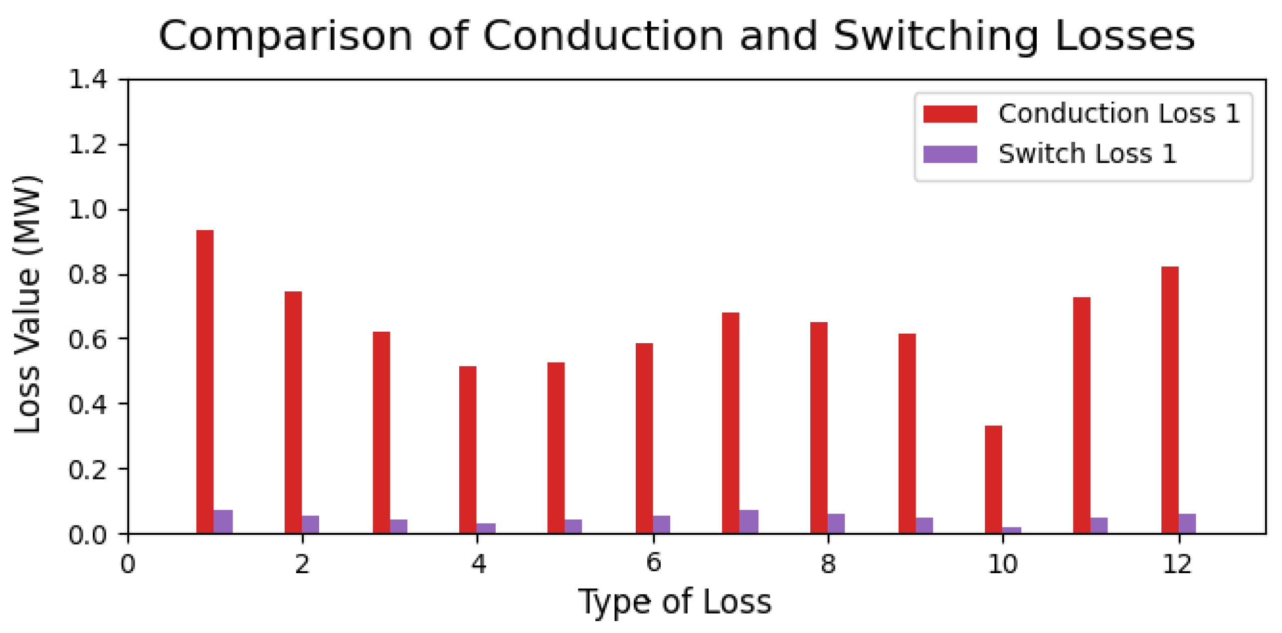
In the third case study, the analysis focused on the influence of power factor variations on total power losses. The objective was to evaluate how changes in power factor affect the balance between active and reactive power, and how these variations impact the converter efficiency. This was assessed using the A B B 5 S N A 1200 E 330100 IGBT module, with parameters extracted from the manufacturer’s data sheet and following the methodology proposed in [86]. Table 2 presents the different power factor values considered, along with the corresponding variations in active and reactive power. Across all scenarios, the apparent power remained approximately constant, allowing us to isolate the specific effect of power factor changes on total losses. The results, shown in Figure 10, demonstrate that the proposed model closely replicates the behaviour reported in [86], confirming its accuracy and reliability.
Analysing the results from Figure 10, it is possible to see the power factor angle varying widely across the scenarios, ranging from −5.3° to 369.9°, indicating alternating conditions between leading and lagging power factors. Consequently, both active and reactive power show significant fluctuations: scenarios 4 and 10 present values of active power close to zero, suggesting almost purely reactive operation, while scenarios 1 and 7 show reactive power values close to zero, corresponding to near-unity power factor conditions. The results demonstrate that as the power factor approaches unity, total system losses tend to increase. This happens because, with apparent power remaining constant, an increase in active power leads to higher current flow, which intensifies resistive losses. Although increasing active power improves power transfer efficiency, it simultaneously raises conduction losses, highlighting the fundamental trade-off between efficiency and thermal performance in converter design.

Grids Based on PRs

In a further analysis, the proposed model was applied to a system study using parameters representative of a grid composed of PRs. The PR grid and system configuration are based on the works presented in [18,21,93], which consider a 10 kV network architecture. The IGBT characteristics were obtained from the FZ1500R33HE3 data sheet, and the results reported in [83] were used for validation. A comparative summary of the results is provided in Table 3, showing that the losses estimated by the proposed model are within the range reported in [83]. These results were obtained by varying the power factor, further confirming the significant influence of this variable on total converter losses. The primary objective of this final case study was to identify and validate a reference scenario with parameters comparable to those expected in a PR-based grid. This alignment enables the prediction of theoretical loss values under realistic operating conditions.

4.4. Case Study 4—PLECS Simulation and Impact of the Number of SMs

This final case study aimed not only to evaluate the relationship between the number of submodules and total losses but also to validate the model against high-fidelity simulation data, as PLECS provides a close approximation of real converter behaviour. The model implemented is shown in Figure 11, in which the main blocks used are displayed. The goal of this model is to quantify both the conduction and switching losses under different scenarios. PLECs allow for parameter customisation that enables high flexibility, returning the instantaneous power loss. However, as these losses are not constant and fluctuate, the average value was taken to allow comparisons.
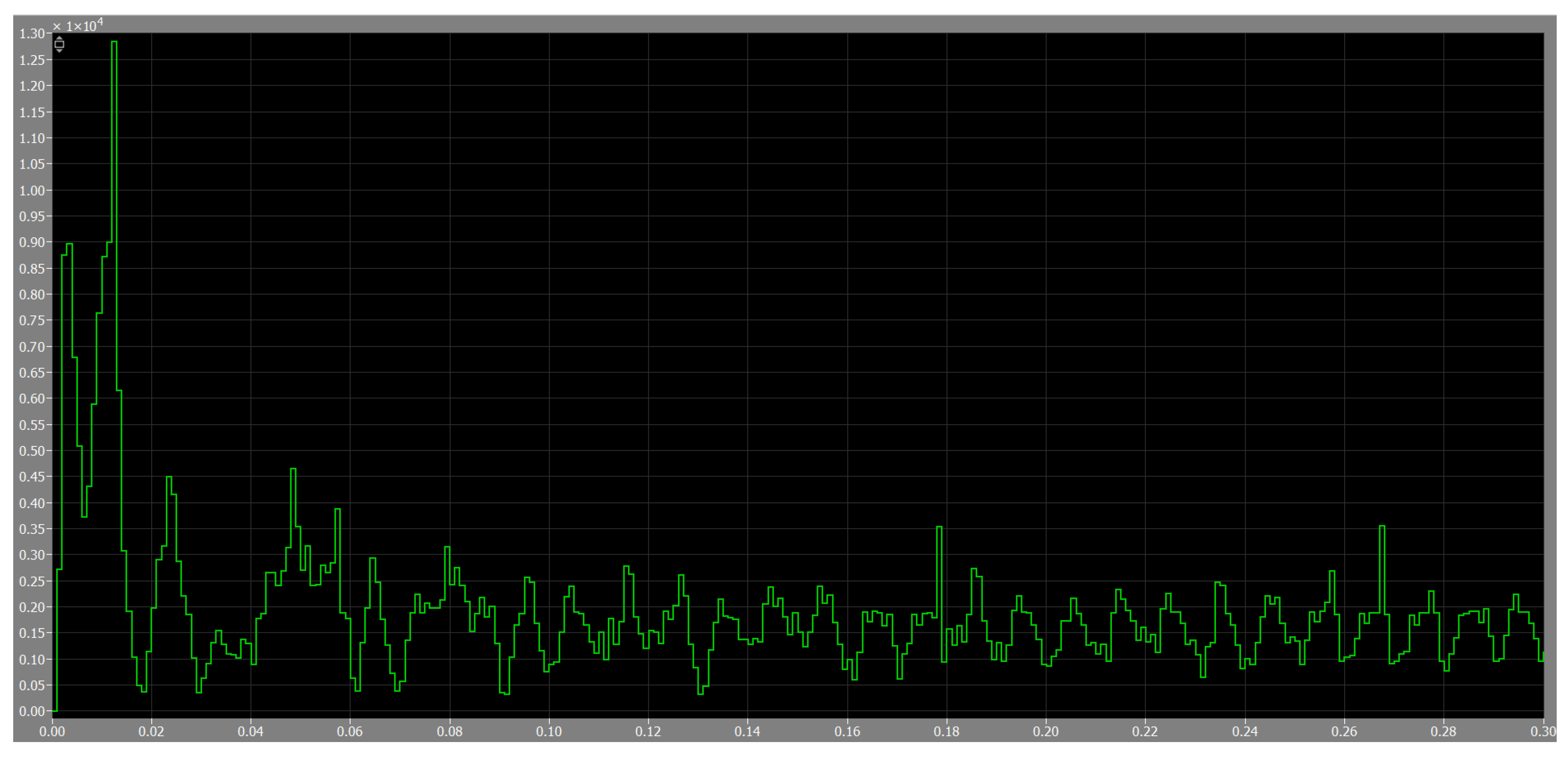
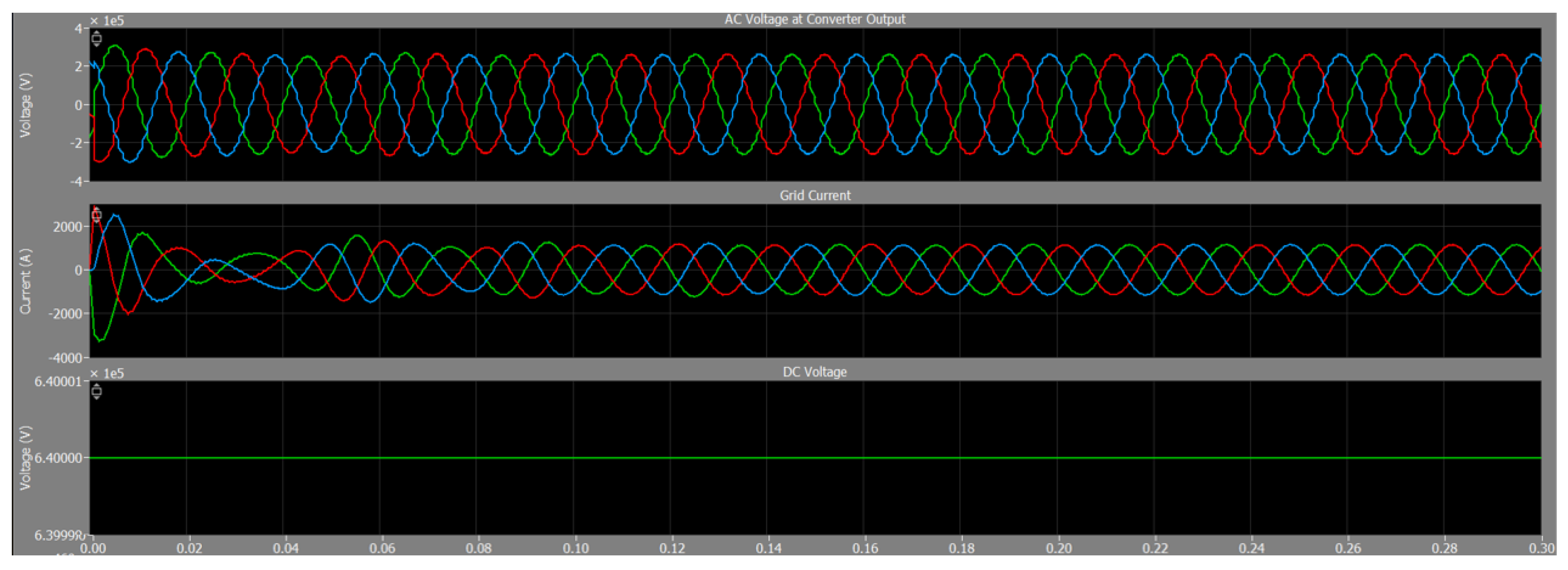
The results of this simulation is shown in Figure 12 and Figure 13. The simulation had a duration of 0.3 s using the 5SNG0600R120500 IGBT module from Hitachi. In this study, the number of SMs in the converter was varied to analyse its influence on total power losses. The system operated with a DC-link voltage of 640 kV, an apparent power of 160 MVA, an RMS AC voltage of 226 kV, and a power factor of 0.9.
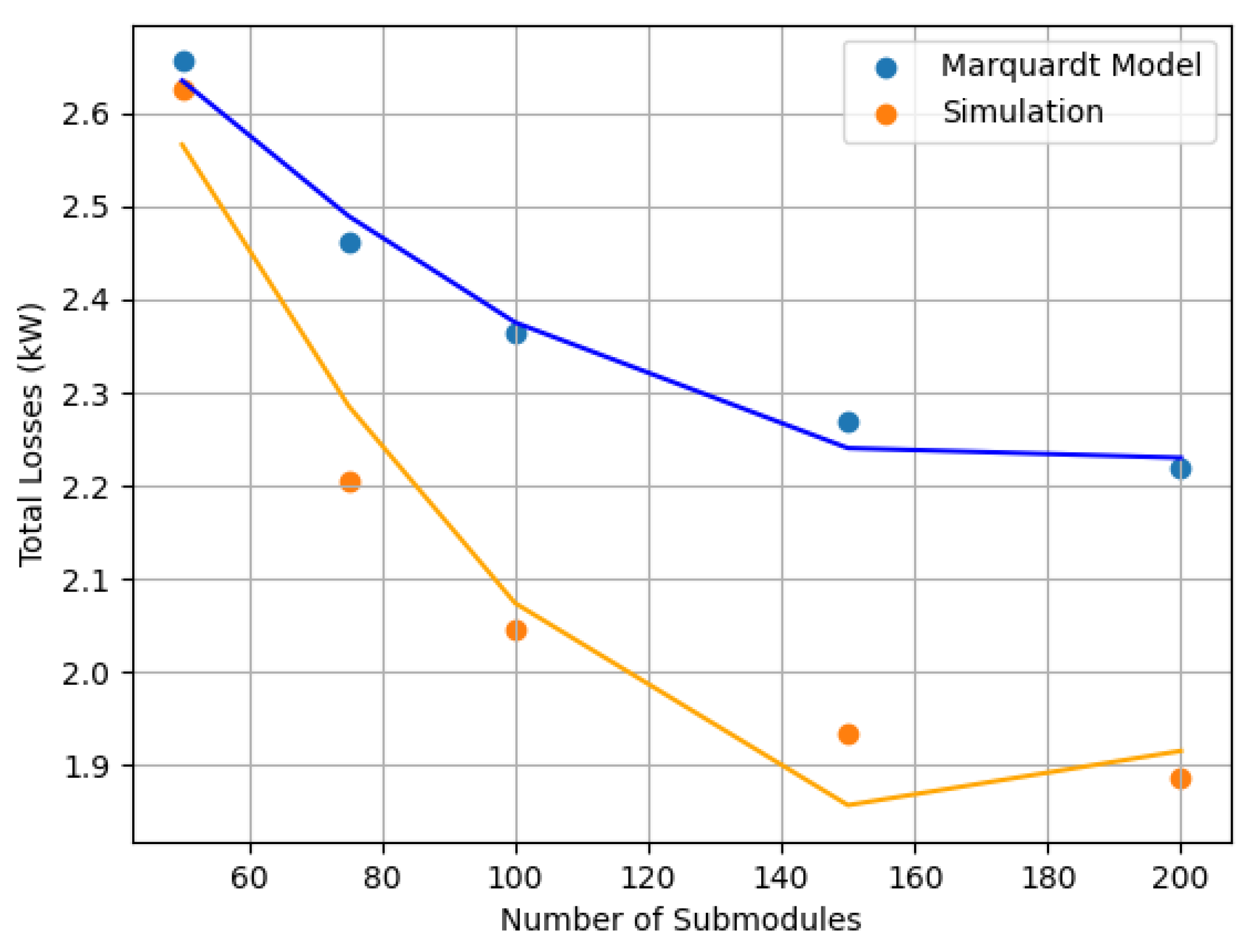
The comparison between the simulated and analytical results, presented in Figure 14, shows a maximum deviation of approximately 18%, which is considered satisfactory given the model’s simplicity and the inherent non-linearities of converter operation.
The results obtained from both the Marquardt model and the PLECS simulation exhibit a clear downward trend, indicating that an increase in the number of submodules leads to a reduction in total converter losses. Although the Marquardt model initially predicts higher loss values, its decline with increasing submodules is less pronounced compared to the simulation results. This suggests that the analytical model is less sensitive to variations in the number of submodules, whereas the simulation data show a steeper decrease, reflecting a stronger reduction in losses as submodules are added. These observations imply that the Marquardt model may overestimate total losses at higher submodule counts but remains more accurate at lower values, while the simulation provides a more consistent estimation across the entire range. The physical explanation behind this behaviour lies in the voltage distribution within the converter: as the number of submodules increases, the voltage applied to each one decreases, resulting in lower current stress and reduced switching losses. Consequently, the overall system efficiency improves. Figure 15 and Figure 16 show this effect by comparing the voltage levels across individual cells for configurations with 50 and 150 submodules, respectively, supporting the analysis presented above.

4.5. Final Results

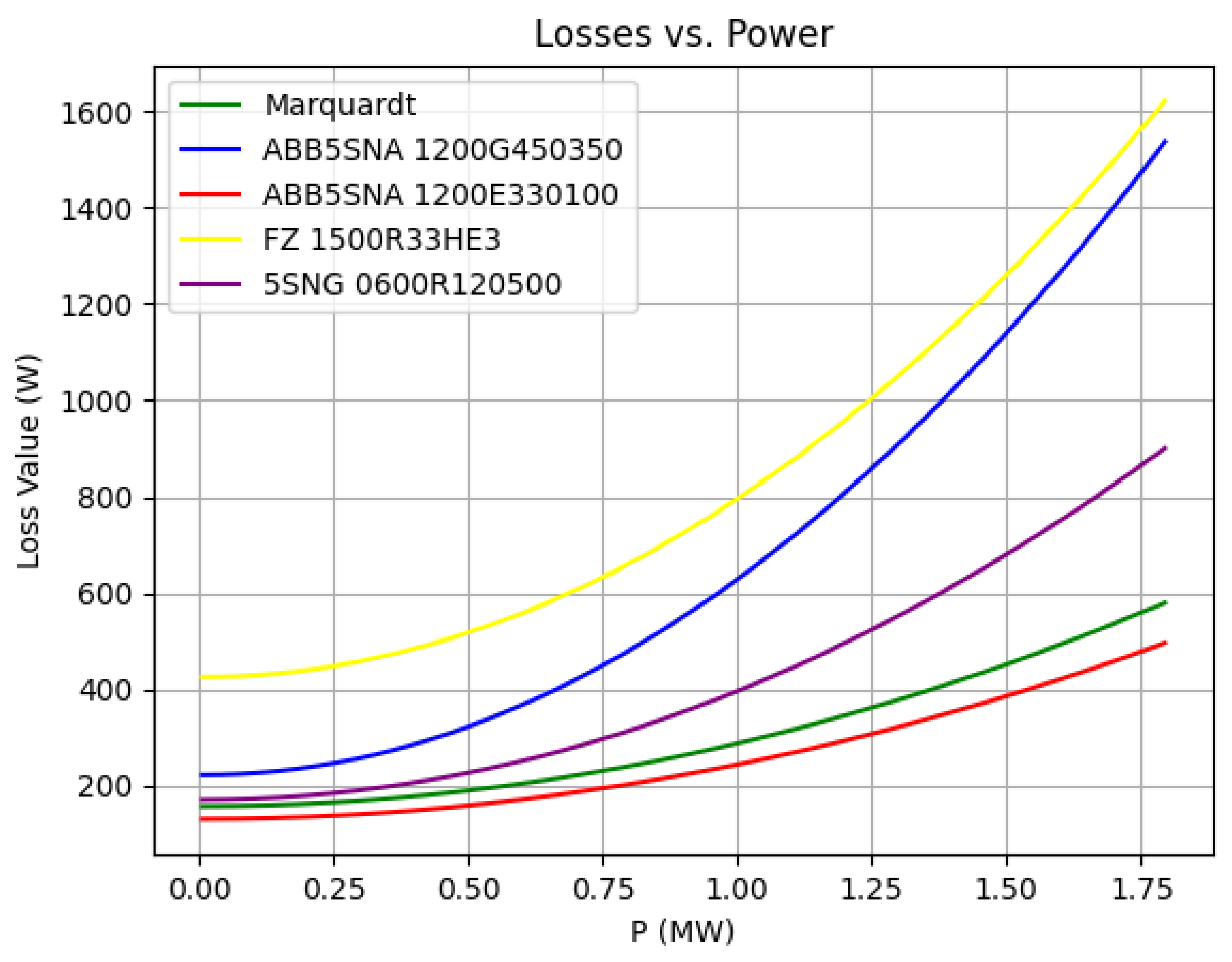
Combining all the insights from the previous case studies, the proposed model was applied to different IGBTs in the industry. The main objective is to provide a clear and simple converter loss curve to support future works involving PR and MMC applications. To achieve this, a comparative analysis of power losses versus power output was conducted across all IGBTs used in the previous studies. The results, presented in Figure 17, clearly illustrate the performance of each device in terms of total power losses. The IGBT selected for integration into the proposed model is the one demonstrating the lowest overall losses. This behaviour can be explained by the internal resistance of each device—since conduction losses represent the dominant component of total losses, lower on-state resistance results in better overall efficiency.
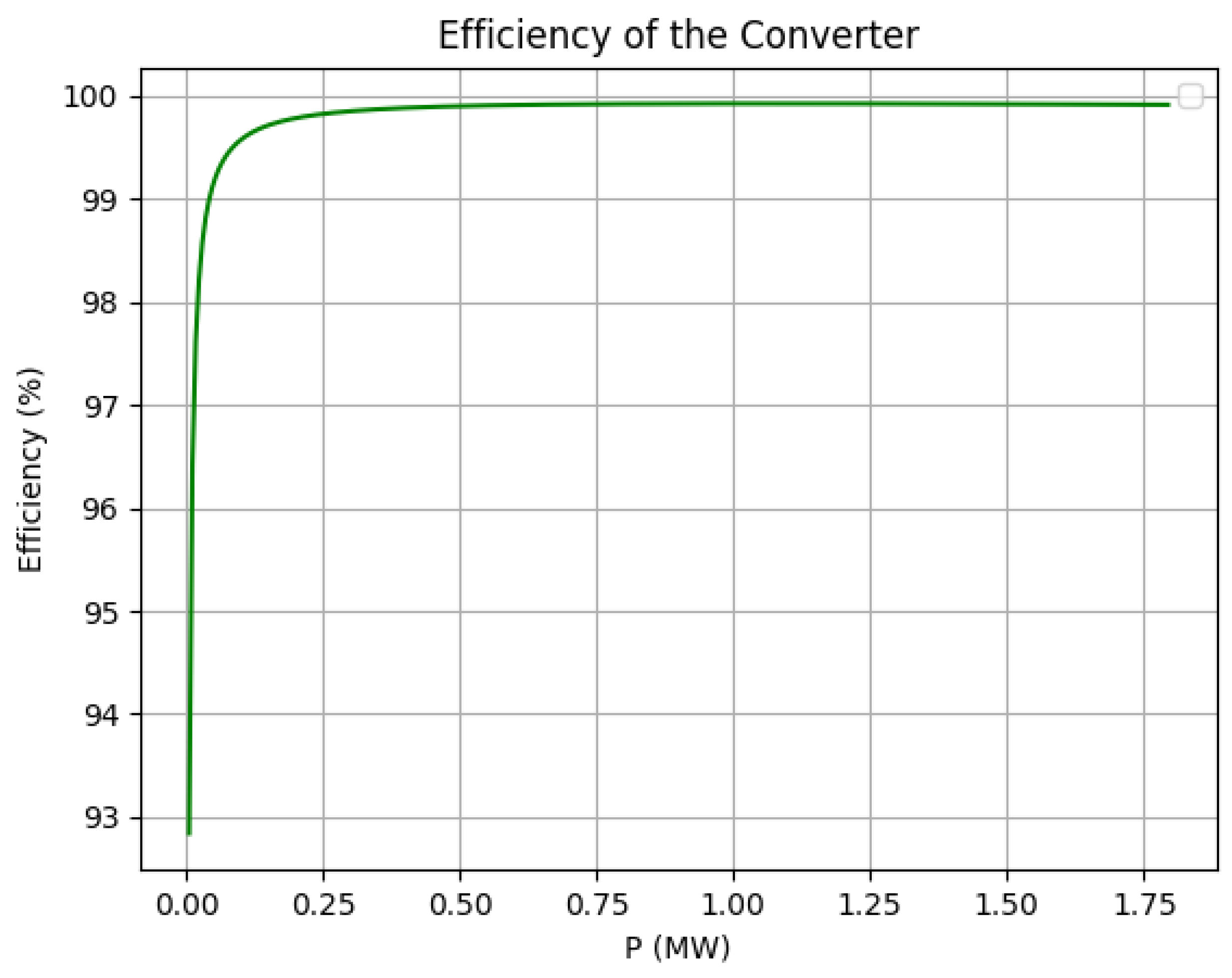
Finally, an efficiency analysis was performed to determine the optimal operating point as the input power varied. As shown in Figure 18, the converter efficiency increases with power output until it reaches a plateau, beyond which it remains stable.

5. Conclusions

This paper addressed one of the main research gaps in the implementation of PR technology: the lack of accurate and validated converter loss models. By developing and evaluating a comprehensive analytical framework based on the Marquardt approach, the proposed model effectively captures conduction and switching losses, enabling reliable efficiency estimation under diverse operating conditions. The proposed model was compared with relevant literature and also with PLECS simulations, confirming its robustness and accuracy. The results demonstrate that both converter design parameters and operating conditions significantly influence PR efficiency. In particular, increasing the number of submodules reduces the voltage and current stress per device, leading to lower total losses, while the choice of IGBT technology plays a decisive role in determining overall performance. Additionally, the analysis of active power, reactive power, and power factor effects provided deeper insight into PR operational behaviour. Specifically, our model shows that operating at unity power factor (90° or 270°, purely active power) resulted in the lowest losses of 3404 W. In contrast, operating in a purely reactive power mode (0°) increased losses to 3798 W—a quantifiable efficiency penalty of nearly 12%. This highlights the impact of reactive power support duties on the PR’s overall performance. Overall, the developed model offers a solid foundation for optimising PR-based grid architectures and supports the broader integration of power electronics into future smart and hybrid AC–DC networks. Although these results are satisfactory for the scope of this paper, several future research directions can be pursued to address its current limitations. For example, implementing and comparing the model in additional simulation environments, such as MATLAB/Simulink, could broaden the evaluation and provide further validation of the results.

Author Contributions

Conceptualisation, V.G.; Methodology, V.G. and J.S.-V.-L.; Validation, V.G. and J.S.-V.-L.; Formal Analysis, V.G. and J.S.-V.-L.; Investigation, V.G., J.S.-V.-L. and A.E.S.-G.; Data Curation, V.G.; Writing—original draft preparation, V.G. and J.S.-V.-L.; writing—review and editing, V.G., J.S.-V.-L., A.E.S.-G. and A.S.; Visualisation, V.G., J.S.-V.-L. and A.E.S.-G.; Supervision, A.E.S.-G. and A.S.; Funding acquisition, A.S. All authors have read and agreed to the published version of the manuscript.

Funding

This work was part of the project PLATON funded by the European Union (NextGenerationEU) and the Ministry for Digital Transformation and Public Administration, under the UNICO I + D Cloud call (Grant No. TSI-063100-2022-010), corresponding to the project “Federated Machine Learning for Electrical Distribution Networks” at Universitat Politècnica de Catalunya. This work was also part of the I+D+i project OPERA (Operation and Planning tools for Enabling Renewable distribution systems Acceleration based on emerging technologies for sustainable computing) with reference PID2024-160822OB-I00 funded by the Ministerio de Ciencia, Innovación y Universidades from Spain. The work of Andreas Sumper was supported by the Catalan Institution for Research and Advanced Studies (ICREA) Academia Program.

Data Availability Statement

No new data were created or analyzed in this study.

Acknowledgments

The authors declare the usage of Generative AI in the microgrids depicted in Figure 2. Additionally, the AI-based tool Grammarly has been used to improve the manuscript’s readability in English. The authors take full responsibility for the content of the publication.

Conflicts of Interest

The authors declare no conflicts of interest.

References

  1. IEA. Global EV Outlook 2024—Moving Towards Increased Affordability; Technical report; IEA: Paris, France, 2024. [Google Scholar]
  2. Lopes, J.A.P.; Madureira, A.G.; Matos, M.; Bessa, R.J.; Monteiro, V.; Afonso, J.L.; Santos, S.F.; Catalão, J.P.S.; Antunes, C.H.; Magalhães, P. The future of power systems: Challenges, trends, and upcoming paradigms. WIREs Energy Environ. 2020, 9, e368. [Google Scholar] [CrossRef]
  3. Gallego, L.; Valino, J.; Lloret-Gallego, P.; Aragues-Penalba, M.; Gonzalez, A.; Richaud, L.; Gabrijelčič, D.; Eytan, A.; Gentile, V.; Kokos, I. BD4OPEM H2020 project. The 4+1 View Model of Software Architecture for enabling AI-based services in distribution grids. In Proceedings of the CIRED 2021—The 26th International Conference and Exhibition on Electricity Distribution, Online Conference, 20–23 September 2021; Volume 2021, pp. 3145–3149. [Google Scholar] [CrossRef]
  4. Gadelha, V.; Bragantini, A.; Sumper, A.; Melendez-Frigola, J.; Kokos, I.; Sánchez, J.A. Flexibility Management for Enhanced Distribution Grid Control and Operation—The Case of FEVER Project. In Proceedings of the 2023 IEEE PES Innovative Smart Grid Technologies Europe (ISGT EUROPE), Grenoble, France, 23–26 October 2023; pp. 1–6. [Google Scholar] [CrossRef]
  5. Otto, B.; Jarke, M. Designing a multi-sided data platform: Findings from the International Data Spaces case. Electron. Mark. 2019, 29, 561–580. [Google Scholar] [CrossRef]
  6. Sun, C.C.; Sebastian Cardenas, D.J.; Hahn, A.; Liu, C.C. Intrusion Detection for Cybersecurity of Smart Meters. IEEE Trans. Smart Grid 2021, 12, 612–622. [Google Scholar] [CrossRef]
  7. Hasan, M.K.; Habib, A.A.; Shukur, Z.; Ibrahim, F.; Islam, S.; Razzaque, M.A. Review on cyber-physical and cyber-security system in smart grid: Standards, protocols, constraints, and recommendations. J. Netw. Comput. Appl. 2023, 209, 103540. [Google Scholar] [CrossRef]
  8. Yan, K.; Li, G.; Zhang, R.; Xu, Y.; Jiang, T.; Li, X. Frequency Control and Optimal Operation of Low-Inertia Power Systems with HVDC and Renewable Energy: A Review. IEEE Trans. Power Syst. 2024, 39, 4279–4295. [Google Scholar] [CrossRef]
  9. Ochoa, D.E.; Galarza-Jimenez, F.; Wilches-Bernal, F.; Schoenwald, D.A.; Poveda, J.I. Control Systems for Low-Inertia Power Grids: A Survey on Virtual Power Plants. IEEE Access 2023, 11, 20560–20581. [Google Scholar] [CrossRef]
  10. Saldaña-González, A.E.; Aragüés-Peñalba, M.; Sumper, A. Distribution network planning method: Integration of a recurrent neural network model for the prediction of scenarios. Electr. Power Syst. Res. 2024, 229, 110125. [Google Scholar] [CrossRef]
  11. Anadón Martínez, V.; Sumper, A.; Saldaña-Gonzalez, A.E.; Gadelha, V. Planning fast-charging stations along highways using probability distribution functions and traffic data. Sustain. Energy Technol. Assess. 2025, 82, 104547. [Google Scholar] [CrossRef]
  12. E. Saldaña-González, A.; Sumper, A.; Anadón-Martínez, V.; Aragüés-Peñalba, M. A machine learning approach for EVCS integration in distribution network based on optimal investment actions. Electr. Power Syst. Res. 2026, 252, 112376. [Google Scholar] [CrossRef]
  13. Perez-Arriaga, I.J. The Transmission of the Future: The Impact of Distributed Energy Resources on the Network. IEEE Power Energy Mag. 2016, 14, 41–53. [Google Scholar] [CrossRef]
  14. Stan, A.; Costinaș, S.; Ion, G. Overview and Assessment of HVDC Current Applications and Future Trends. Energies 2022, 15, 1193. [Google Scholar] [CrossRef]
  15. Kroposki, B.; Johnson, B.; Zhang, Y.; Gevorgian, V.; Denholm, P.; Hodge, B.M.; Hannegan, B. Achieving a 100% Renewable Grid: Operating Electric Power Systems with Extremely High Levels of Variable Renewable Energy. IEEE Power Energy Mag. 2017, 15, 61–73. [Google Scholar] [CrossRef]
  16. Zhou, K.; Yang, S.; Shao, Z. Energy Internet: The business perspective. Appl. Energy 2016, 178, 212–222. [Google Scholar] [CrossRef]
  17. Takuno, T.; Koyama, M.; Hikihara, T. In-Home Power Distribution Systems by Circuit Switching and Power Packet Dispatching. In Proceedings of the 2010 First IEEE International Conference on Smart Grid Communications, Gaithersburg, MD, USA, 4–6 October 2010; pp. 427–430. [Google Scholar] [CrossRef]
  18. Gadelha, V.; Sumper, A.; Bullich-Massagué, E.; Aragüés-Peñalba, M. Electrical Grids Based on Power Routers: Definition, Architecture and Modeling. IEEE Access 2023, 11, 10004–10017. [Google Scholar] [CrossRef]
  19. Bullich-Massagué, E.; Díaz-González, F.; Aragüés-Peñalba, M.; Girbau-Llistuella, F.; Olivella-Rosell, P.; Sumper, A. Microgrid clustering architectures. Appl. Energy 2018, 212, 340–361. [Google Scholar] [CrossRef]
  20. Guan, Y.; Wei, B.; Guerrero, J.M.; Vasquez, J.C.; Gui, Y. An overview of the operation architectures and energy management system for multiple microgrid clusters. iEnergy 2022, 1, 306–314. [Google Scholar] [CrossRef]
  21. Gadelha, V.; Bullich-Massagué, E.; Sumper, A. Optimal Power Flow in electrical grids based on power routers. Electr. Power Syst. Res. 2024, 234, 110581. [Google Scholar] [CrossRef]
  22. Soto, E.A.; Bosman, L.B.; Wollega, E.; Leon-Salas, W.D. Peer-to-peer energy trading: A review of the literature. Appl. Energy 2021, 283, 116268. [Google Scholar] [CrossRef]
  23. Jiang, X.; Sun, C.; Cao, L.; Liu, J.; Law, N.F.; Loo, K. Peer-to-peer energy trading in energy local area network considering decentralized energy routing. Sustain. Energy Grids Netw. 2023, 34, 100994. [Google Scholar] [CrossRef]
  24. National Grid, E. Pathway to 2030—A Hollistic Network Design to Support Offshore Wind Deployment for Net Zero. 2022. Available online: https://www.nationalgrideso.com/document/262676/download (accessed on 20 June 2024).
  25. Monteiro, V.; Afonso, J.L. The Future of Electrical Power Grids: A Direction Rooted in Power Electronics. Energies 2023, 16, 4929. [Google Scholar] [CrossRef]
  26. Rodriguez-Bernuz, J.M.; Prieto-Araujo, E.; Girbau-Llistuella, F.; Sumper, A.; Villafafila-Robles, R.; Vidal-Clos, J.A. Experimental validation of a single phase Intelligent Power Router. Sustain. Energy Grids Netw. 2015, 4, 1–15. [Google Scholar] [CrossRef]
  27. Xu, Y.; Zhang, J.; Wang, W.; Juneja, A.; Bhattacharya, S. Energy router: Architectures and functionalities toward Energy Internet. In Proceedings of the 2011 IEEE International Conference on Smart Grid Communications (SmartGridComm), Brussels, Belgium, 17–20 October 2011; pp. 31–36. [Google Scholar] [CrossRef]
  28. Sánchez-Squella, A.; Ortega, R.; Griño, R.; Malo, S. Dynamic Energy Router. IEEE Control Syst. Mag. 2010, 30, 72–80. [Google Scholar] [CrossRef]
  29. Zhao, X.; Liu, Y.; Chai, X.; Guo, X.; Wang, X.; Zhang, C.; Wei, T.; Shi, C.; Jia, D. Multimode Operation Mechanism Analysis and Power Flow Flexible Control of a New Type of Electric Energy Router for Low-Voltage Distribution Network. IEEE Trans. Smart Grid 2022, 13, 3594–3606. [Google Scholar] [CrossRef]
  30. Adu, J.A.; Furuta, F.; Kohno, T. Robust DC microgrid operation with power routing capabilities. Energy Rep. 2022, 8, 1473–1480. [Google Scholar] [CrossRef]
  31. Gu, B.; Mao, C.; Liu, B.; Wang, D.; Fan, H.; Zhu, J.; Sang, Z. Optimal Charge/Discharge Scheduling for Batteries in Energy Router-Based Microgrids of Prosumers via Peer-to-Peer Trading. IEEE Trans. Sustain. Energy 2022, 13, 1315–1328. [Google Scholar] [CrossRef]
  32. Deng, J.; Wang, X.; Chen, T.; Meng, F. An energy router based on multi-hybrid energy storage system with energy coordinated management strategy in island operation mode. Renew. Energy 2023, 212, 274–284. [Google Scholar] [CrossRef]
  33. Wang, R.; Jiang, S.; Ma, D.; Sun, Q.; Zhang, H.; Wang, P. The Energy Management of Multiport Energy Router in Smart Home. IEEE Trans. Consum. Electron. 2022, 68, 344–353. [Google Scholar] [CrossRef]
  34. Liu, J.; Tang, F.; Wang, M.; Chen, P.; Xu, Z.; Wu, L.; Wang, W. A home energy router and energy management strategy for AC/DC hybrid sources and consumers. In Proceedings of the 2018 13th IEEE Conference on Industrial Electronics and Applications (ICIEA), Wuhan, China, 31 May–2 June 2018; pp. 1498–1503. [Google Scholar] [CrossRef]
  35. Liu, Y.; Chen, X.; Wu, Y.; Yang, K.; Zhu, J.; Li, B. Enabling the Smart and Flexible Management of Energy Prosumers via the Energy Router with Parallel Operation Mode. IEEE Access 2020, 8, 35038–35047. [Google Scholar] [CrossRef]
  36. Zhu, Y.; Wang, Y.; Teng, J.; Sun, X.; Qi, M.; Zhao, W.; Li, X. Partial Power Conversion and High Voltage Ride-Through Scheme for a PV-Battery Based Multiport Multi-Bus Power Router. IEEE Access 2021, 9, 17020–17029. [Google Scholar] [CrossRef]
  37. Joseph, A.; Balachandra, P. Smart Grid to Energy Internet: A Systematic Review of Transitioning Electricity Systems. IEEE Access 2020, 8, 215787–215805. [Google Scholar] [CrossRef]
  38. Liu, B.; Zhu, B.; Guan, Z.; Mao, C.; Wang, D. Energy router interconnection system: A solution for new distribution network architecture toward future carbon neutrality. Energy Convers. Econ. 2022, 3, 181–200. [Google Scholar] [CrossRef]
  39. Sun, L.; Jiang, W.; Hashimoto, S.; Lin, Z.; Kawaguchi, T. Multiport Energy Router for DC Grid Clusters. IEEE J. Emerg. Sel. Top. Power Electron. 2024, 12, 1666–1682. [Google Scholar] [CrossRef]
  40. Liu, B.; Peng, Y.; Xu, J.; Mao, C.; Wang, D.; Duan, Q. Design and Implementation of Multiport Energy Routers Toward Future Energy Internet. IEEE Trans. Ind. Appl. 2021, 57, 1945–1957. [Google Scholar] [CrossRef]
  41. Kandula, R.P.; Prasai, A.; Chen, H.; Mayor, R.; Lambert, F.; Heidel, T.; Schauder, C.; Divan, D. Design considerations and experimental results for a 12.47-kV 3-phase 1 MVA power router. In Proceedings of the 2015 IEEE Energy Conversion Congress and Exposition (ECCE), Montreal, QC, Canada, 20–24 September 2015; pp. 5000–5007. [Google Scholar] [CrossRef]
  42. Kado, Y.; Shichijo, D.; Deguchi, I.; Iwama, N.; Kasashima, R.; Wada, K. Power flow control of three-way isolated DC/DC converter for Y-configuration power router. In Proceedings of the 2015 IEEE 2nd International Future Energy Electronics Conference (IFEEC), Taipei, Taiwan, 1–4 November 2015; pp. 1–5. [Google Scholar] [CrossRef]
  43. Kandula, R.P.; Chen, H.; Prasai, A.; Lambert, F.; Heidel, T.; Schauder, C.; Schatz, J.; Powell, T.; Divan, D. Field test results for a 3-phase 12.47 kV 1 MVA power router. In Proceedings of the 2016 IEEE Energy Conversion Congress and Exposition (ECCE), Milwaukee, WI, USA, 18–22 September 2016; pp. 1–8. [Google Scholar] [CrossRef]
  44. Chen, H.; Iyer, A.R.; Harley, R.G.; Divan, D. Dynamic Grid Power Routing Using Controllable Network Transformers (CNTs) with Decoupled Closed-Loop Controller. IEEE Trans. Ind. Appl. 2015, 51, 2361–2372. [Google Scholar] [CrossRef]
  45. Mauger, M.J.; Kandula, P.; Lambert, F.; Divan, D. Grounded Controllable Network Transformer for Cost-Effective Grid Control. In Proceedings of the 2018 IEEE Energy Conversion Congress and Exposition (ECCE), Portland, OR, USA, 23–27 September 2018; pp. 3732–3739. [Google Scholar] [CrossRef]
  46. Chen, R.; Yang, Y.; Jin, T. A hierarchical coordinated control strategy based on multi-port energy router of urban rail transit. Prot. Control Mod. Power Syst. 2022, 7, 15. [Google Scholar] [CrossRef]
  47. Liu, Y.; Liu, C.; Wang, W.; Liu, S.; Chen, Y. A Novel Wired/Wireless Hybrid Multiport Energy Router for Dynamic EV Energy Internet with Grid-Tied and Islanded Operations. IEEE Trans. Ind. Electron. 2024, 71, 3559–3571. [Google Scholar] [CrossRef]
  48. Li, P.; Ji, H.; Wang, C.; Zhao, J.; Song, G.; Ding, F.; Wu, J. Coordinated Control Method of Voltage and Reactive Power for Active Distribution Networks Based on Soft Open Point. IEEE Trans. Sustain. Energy 2017, 8, 1430–1442. [Google Scholar] [CrossRef]
  49. Rezaeian-Marjani, S.; Talavat, V.; Galvani, S. Impact of soft open point (SOP) on distribution network predictability. Int. J. Electr. Power Energy Syst. 2022, 136, 107676. [Google Scholar] [CrossRef]
  50. Jiang, X.; Zhou, Y.; Ming, W.; Yang, P.; Wu, J. An Overview of Soft Open Points in Electricity Distribution Networks. IEEE Trans. Smart Grid 2022, 13, 1899–1910. [Google Scholar] [CrossRef]
  51. Qin, F.; Gao, F.; Yu, A. A Soft Open Points with Direct AC-AC Modular Multilevel Converter. In Proceedings of the 2019 4th IEEE Workshop on the Electronic Grid (eGRID), Xiamen, China, 11–14 November 2019; pp. 1–5. [Google Scholar] [CrossRef]
  52. Deakin, M. Comparative analysis of services from soft open points using cost–benefit analysis. Appl. Energy 2023, 333, 120618. [Google Scholar] [CrossRef]
  53. Wang, Y.; Su, X.; Song, M.; Jiang, W.; Shahidehpour, M.; Xu, Q. Sequential Load Restoration with Soft Open Points and Time-Dependent Cold Load Pickup for Resilient Distribution Systems. IEEE Trans. Smart Grid 2023, 14, 3427–3438. [Google Scholar] [CrossRef]
  54. Deakin, M. Multiplexing Power Converters for Cost-Effective and Flexible Soft Open Points. IEEE Trans. Smart Grid 2024, 15, 260–271. [Google Scholar] [CrossRef]
  55. Ji, H.; Wang, C.; Li, P.; Zhao, J.; Song, G.; Ding, F.; Wu, J. An enhanced SOCP-based method for feeder load balancing using the multi-terminal soft open point in active distribution networks. Appl. Energy 2017, 208, 986–995. [Google Scholar] [CrossRef]
  56. Nguyen, T.T.; Nguyen, T.T.; Nguyen, H.P. Optimal soft open point placement and open switch position selection simultaneously for power loss reduction on the electric distribution network. Expert Syst. Appl. 2024, 238, 121743. [Google Scholar] [CrossRef]
  57. Zhang, J.; Feng, X.; Zhou, J.; Zang, J.; Wang, J.; Shi, G.; Cai, X.; Li, Y. Series–Shunt Multiport Soft Normally Open Points. IEEE Trans. Ind. Electron. 2023, 70, 10811–10821. [Google Scholar] [CrossRef]
  58. Abe, R.; Taoka, H.; McQuilkin, D. Digital Grid: Communicative Electrical Grids of the Future. IEEE Trans. Smart Grid 2011, 2, 399–410. [Google Scholar] [CrossRef]
  59. Nguyen, P.H.; Kling, W.L.; Ribeiro, P.F. Smart Power Router: A Flexible Agent-Based Converter Interface in Active Distribution Networks. IEEE Trans. Smart Grid 2011, 2, 487–495. [Google Scholar] [CrossRef]
  60. Rojas-Cessa, R.; Xu, Y.; Grebel, H. Management of a smart grid with controlled-delivery of discrete power levels. In Proceedings of the 2013 IEEE International Conference on Smart Grid Communications (SmartGridComm), Vancouver, BC, Canada, 21–24 October 2013; pp. 1–6. [Google Scholar] [CrossRef]
  61. Fujii, N.; Takahashi, R.; Hikihara, T. Networked power packet dispatching system for multi-path routing. In Proceedings of the 2014 IEEE/SICE International Symposium on System Integration, Tokyo, Japan, 13–15 December 2014; pp. 357–362. [Google Scholar] [CrossRef]
  62. Sugiyama, H. Pulsed power network based on decentralized intelligence for reliable and low loss electrical power distribution. In Proceedings of the 2014 IEEE Symposium on Computational Intelligence Applications in Smart Grid (CIASG), Orlando, FL, USA, 9–12 December 2014; pp. 1–6. [Google Scholar] [CrossRef]
  63. Takahashi, R.; Tashiro, K.; Hikihara, T. Router for Power Packet Distribution Network: Design and Experimental Verification. IEEE Trans. Smart Grid 2015, 6, 618–626. [Google Scholar] [CrossRef]
  64. Lin, J.; Li, V.O.K.; Leung, K.; Lam, A.Y.S. Optimal Power Flow with Power Flow Routers. IEEE Trans. Power Syst. 2017, 32, 531–543. [Google Scholar] [CrossRef]
  65. Ma, J.; Song, L.; Li, Y. Optimal Power Dispatching for Local Area Packetized Power Network. IEEE Trans. Smart Grid 2018, 9, 4765–4776. [Google Scholar] [CrossRef]
  66. Hikihara, T.; Tashiro, K.; Kitamori, Y.; Takahashi, R. Power Packetization and Routing for Smart Management of Electricity. In Proceedings of the 10th International Energy Conversion Engineering Conference, Atlanta, GA, USA, 30 July–1 August 2012. [Google Scholar] [CrossRef]
  67. Stalling, B.P.; Clemmer, T.; Mantooth, H.A.; Motte, R.; Xu, H.; Price, T.; Dougal, R. Design and evaluation of a universal power router for residential applications. In Proceedings of the 2012 IEEE Energy Conversion Congress and Exposition (ECCE), Raleigh, NC, USA, 15–20 September 2012; pp. 587–594. [Google Scholar] [CrossRef]
  68. Khodabakhsh, J.; Moschopoulos, G. Uncertainty Reduction for Data Centers in Energy Internet by a Compact AC-DC Energy Router and Coordinated Energy Management Strategy. In Proceedings of the 2020 IEEE Energy Conversion Congress and Exposition (ECCE), Detroit, MI, USA, 11–15 October 2020; pp. 4668–4673. [Google Scholar] [CrossRef]
  69. An, R.; Liu, J.; Liu, Z.; Song, Z. Flexible Transfer Converters Enabling Autonomous Control and Power Dispatch of Microgrids. IEEE Trans. Power Electron. 2022, 37, 13767–13781. [Google Scholar] [CrossRef]
  70. Maulik, S.; John, V. Grid Current Feed-forward based Transfer Scheme for Grid-tied Inverters with Anti-islanding Schemes. In Proceedings of the 2022 IEEE International Conference on Power Electronics, Drives and Energy Systems (PEDES), Jaipur, India, 14–17 December 2022; pp. 1–6. [Google Scholar] [CrossRef]
  71. Guo, H.; Wang, F.; Luo, J.; Zhang, L. Review of energy routers applied for the energy internet integrating renewable energy. In Proceedings of the 2016 IEEE 8th International Power Electronics and Motion Control Conference (IPEMC-ECCE Asia), Hefei, China, 22–26 May 2016; pp. 1997–2003. [Google Scholar] [CrossRef]
  72. Bhattacharjee, A.K.; Kutkut, N.; Batarseh, I. Review of Multiport Converters for Solar and Energy Storage Integration. IEEE Trans. Power Electron. 2019, 34, 1431–1445. [Google Scholar] [CrossRef]
  73. Chen, T.; Song, Y.; Hill, D.J.; Lam, A.Y.S. Chance-Constrained OPF in Droop-Controlled Microgrids with Power Flow Routers. IEEE Trans. Smart Grid 2022, 13, 2601–2613. [Google Scholar] [CrossRef]
  74. Huang, K.; Li, Y.; Zhang, X.; Liu, L.; Zhu, Y.; Meng, X. Research on power control strategy of household-level electric power router based on hybrid energy storage droop control. Prot. Control Mod. Power Syst. 2021, 6, 1–13. [Google Scholar] [CrossRef]
  75. Niu, S.; Liu, T.; Liu, X.; Ren, Q.; Chen, Z.; Chen, A. A Virtual Inertia Control Strategy with Current Feedforward to Improve Voltage Stability for Power Router. In Proceedings of the IECON 2021—47th Annual Conference of the IEEE Industrial Electronics Society, Toronto, ON, Canada, 13–16 October 2021; pp. 1–6. [Google Scholar] [CrossRef]
  76. Hu, R.; Wang, W.; Wu, X.; Chen, Z.; Ma, W. Interval optimization based coordinated control for distribution networks with energy storage integrated soft open points. Int. J. Electr. Power Energy Syst. 2022, 136, 107725. [Google Scholar] [CrossRef]
  77. Rodriguez-Bernuz, J.M.; Gadelha, V.; Sumper, A.; Bullich-Massagué, E. Droop-Based Power Routers for Enhanced Resilience in Networked Grids. Electr. Power Syst. Res. 2024, 243, 111475. [Google Scholar] [CrossRef]
  78. Zhu, L.; Rong, X.; Zhao, J.; Zhang, H.; Zhang, H.; Jia, C.; Ma, G. Topology optimization of AC/DC hybrid distribution network with energy router based on power flow calculation. Energy Rep. 2022, 8, 1622–1638. [Google Scholar] [CrossRef]
  79. Zhu, Y.; Wu, H.; Zhang, Z.; Zong, C.; Xu, D. Optimal power flow research of AC–DC hybrid grid with multiple energy routers. Electr. Power Syst. Res. 2024, 228, 110090. [Google Scholar] [CrossRef]
  80. Wu, T.; Zhao, C.; Zhang, Y.J.A. Distributed AC-DC Optimal Power Dispatch of VSC-Based Energy Routers in Smart Microgrids. IEEE Trans. Power Syst. 2021, 36, 4457–4470. [Google Scholar] [CrossRef]
  81. Liu, Z.; Zheng, J.; Gui, Y. Electric Energy Router Loss Modeling Method Based on Port Loss Model for Operation States. In Proceedings of the 2021 IEEE Sustainable Power and Energy Conference (iSPEC), Nanjing, China, 23–25 December 2021; pp. 2749–2754. [Google Scholar] [CrossRef]
  82. Tao, Q.; Ma, J.; Zhu, M.; Duan, Q.; Sha, G. Comparative Evaluation of Multiport DC Power Router for DC Distribution Grid. In Proceedings of the 2020 IEEE 9th International Power Electronics and Motion Control Conference (IPEMC2020-ECCE Asia), Nanjing, China, 29 November–2 December 2020; pp. 3263–3268. [Google Scholar] [CrossRef]
  83. Ertürk, F.; Hava, A.M. A detailed power loss analysis of modular multilevel converter. In Proceedings of the 2015 IEEE Applied Power Electronics Conference and Exposition (APEC), Charlotte, NC, USA, 15–19 March 2015; pp. 1658–1665. [Google Scholar] [CrossRef]
  84. Wang, H.; Tang, G.; He, Z.; Cao, J.; Zhang, X. Analytical approximate calculation of losses for modular multilevel converters. IET Gener. Transm. Distrib. 2015, 9, 2455–2465. [Google Scholar] [CrossRef]
  85. Song, Y.; Luo, Y.; Xiong, X. Loss distribution analysis and accurate calculation method for bulk-power MMC. Prot. Control Mod. Power Syst. 2023, 8, 1–15. [Google Scholar] [CrossRef]
  86. Zhang, Z.; Xu, Z.; Xue, Y. Valve Losses Evaluation Based on Piecewise Analytical Method for MMC–HVDC Links. IEEE Trans. Power Deliv. 2014, 29, 1354–1362. [Google Scholar] [CrossRef]
  87. Zhang, Y.; Wang, H.; Wang, Z.; Blaabjerg, F.; Saeedifard, M. System-Level Power Loss Evaluation of Modular Multilevel Converters. In Proceedings of the 2019 IEEE Energy Conversion Congress and Exposition, ECCE, Baltimore, MD, USA, 29 September–3 October 2019; pp. 6797–6804. [Google Scholar] [CrossRef]
  88. Allebrod, S.; Hamerski, R.; Marquardt, R. New transformerless, scalable Modular Multilevel Converters for HVDC-transmission. In Proceedings of the 2008 IEEE Power Electronics Specialists Conference, Rhodes, Greece, 15–19 June 2008; pp. 174–179. [Google Scholar] [CrossRef]
  89. Rodrigues, S.; Papadopoulos, A.; Kontos, E.; Todorcevic, T.; Bauer, P. Steady-State Loss Model of Half-Bridge Modular Multilevel Converters. IEEE Trans. Ind. Appl. 2016, 52, 2415–2425. [Google Scholar] [CrossRef]
  90. Saad, H.; Dennetière, S.; Mahseredjian, J.; Delarue, P.; Guillaud, X.; Peralta, J.; Nguefeu, S. Modular Multilevel Converter Models for Electromagnetic Transients. IEEE Trans. Power Deliv. 2014, 29, 1481–1489. [Google Scholar] [CrossRef]
  91. Yang, L.; Li, Y.; Li, Z.; Wang, P.; Xu, S.; Gou, R. Loss Optimization of MMC by Second-Order Harmonic Circulating Current Injection. IEEE Trans. Power Electron. 2018, 33, 5739–5753. [Google Scholar] [CrossRef]
  92. Huang, S.; Liao, W.; Liu, P.; Tang, W.; Huang, S. Analysis and calculation on switching frequency and switching losses of modular multilevel converter with maximum sub-module capacitor voltage deviation. IET Power Electron. 2016, 9, 188–197. [Google Scholar] [CrossRef]
  93. Gadelha, V.; Sumper, A.; Bullich-Massague, E. Impact of converter losses in optimal power flow for hybrid AC-DC networks based on power routers. CSEE J. Power Energy Syst. 2025; early access. Available online: https://ieeexplore.ieee.org/stamp/stamp.jsp?arnumber=11006468 (accessed on 4 November 2025).
Figure 1. The main challenges that the future power system must overcome.
Electricity 07 00005 g001
Figure 2. Example of a PR interfacing with different microgrids.
Electricity 07 00005 g002
Figure 3. Different PR design concepts found in the literature. (a) Soft open points; (b) in-home energy router; (c) power packet router; (d) multi-port power router; (e) transformer-based router.
Electricity 07 00005 g003
Figure 4. Number of publications for each PR design throughout the years.
Electricity 07 00005 g004
Figure 5. Generic scheme of an n-ports VSC-based power router.
Electricity 07 00005 g005
Figure 6. The internal port of a PR as a three-phase n-level MMC converter with half bridge sub-modules.
Electricity 07 00005 g006
Figure 7. Loss curves obtained by the proposed model.
Electricity 07 00005 g007
Figure 8. Curve losses for a reactive power of 3 var.
Electricity 07 00005 g008
Figure 9. Curve losses for a reactive power of 6.5 var.
Electricity 07 00005 g009
Figure 10. Losses obtained by the model.
Electricity 07 00005 g010
Figure 11. PLECS model implemented for MMC loss assessment.
Electricity 07 00005 g011
Figure 12. Simulation results for instantaneous losses inside the converter.
Electricity 07 00005 g012
Figure 13. Simulation results for instantaneous AC and DC three-phase voltage and AC current.
Electricity 07 00005 g013
Figure 14. Loss comparison using the simulator and our model.
Electricity 07 00005 g014
Figure 15. Voltage distribution in each cell for SM = 50.
Electricity 07 00005 g015
Figure 16. Voltage distribution in each cell for SM = 150.
Electricity 07 00005 g016
Figure 17. Loss comparison using different IGBTs.
Electricity 07 00005 g017
Figure 18. Efficiency curve of ABB5SNA 1200E330100.
Electricity 07 00005 g018
Table 1. Table comparing different PR designs.
Ref.PR DesignAllow Line PF ControlConsiders HVDC LinesControl StrategyReference SourceScope
[21](d)×DistributedOPF-basedSOC-relaxed OPF formulation for PR-based networks
[73](e)×DistributedOPF-basedOPF with transient stability analysis
[68](c)DistributedRouting AlgorithmUsage of PR to connect AC and DC energy hubs
[74](b)××CentralisedDroop-basedIn-home applications with hybrid energy storage
[75](b)××CentralisedDroop-basedImprove voltage stability through virtual inertia
[49](a)×CentralisedPPF-basedNetwork predictability through probabilistic evaluation
[76](a)×CentralisedInterval OptimisationOptimisation of network efficiency
[77](d)×DistributedDroop-basedEnhances resiliency in PR-based networks
[23](c), (d)×DistributedRouting OptimisationPeer-to-peer energy trading using PRs
[27](d), (e)×CentralisedNot specifiedInitial conceptualisation of PR architecture and communication
[28](b)×CentralisedPI controllerInitial conceptualisation of the dynamic energy router
[78](d)DistributedTopology optimisationTopology optimisation of hybrid AC-DC PR-based networks
[29](b), (d)×CentralisedDoF flexible controlControl mechanisms for a series-parallel PR architecture
[32](b), (d)CentralisedESS OptimisationPR based on multi-hybrid energy storage system
[30](b)××CentralisedFlexible DroopOperation schemes for PR-based DC microgrid
[41](e)×CentralisedUser-definedDesign and experimentation of transformer-based PR
[42](e)×CentralisedUser-definedExperimental results for 3-winding transformer-based PR
[79](d)DistributedOPF-basedOPF formulation for hybrid AC-DC PR-based networks
[48](a)×DistributedVolt-VAR ControlModelling and control of reactive power using SOPs
[53](a)×DistributedDSR OptimisationSequential load restoration model considering SOPs
[61](c)×DistributedRouting AssignmentExperimental results for a power packet dispatching system
[34](b)××CentralisedLocal HEMSHome energy router for AC-DC interface integration
[65](c)×DistributedRouting OptimisationOptimal dispatch protocol for multi-channel PR
[80](d)DistributedOPF-basedSDP-relaxed OPF formulation for PR-based networks
[51](a), (d)×CentralisedP-Q ControlDirect AC-AC MMC-based SOP design
Table 2. Different scenarios used for the simulation.
No.P (MW)Q (Mvar)Power Factor (°)
1409.1−38.2−5.3
2326.0203.231.9
3243.6283.949.4
40.7365.089.9
5−236.6285.7129.6
6−314.2206.2146.7
7−391.1−33.5184.9
8−314.0−275.0221.2
9−236.6−355.7236.4
10−0.5−436.6269.9
11243.5−357.2304.3
12325.8−277.7319.6
Table 3. Comparison of converter losses between [83] and the proposed model.
Power Factor (°)Losses in [83] (W)Proposed Model (W)
03000–43003798
902400–36503404
1803200–53753744
2702650–50003404
Disclaimer/Publisher’s Note: The statements, opinions and data contained in all publications are solely those of the individual author(s) and contributor(s) and not of MDPI and/or the editor(s). MDPI and/or the editor(s) disclaim responsibility for any injury to people or property resulting from any ideas, methods, instructions or products referred to in the content.