Article

Symmetrical Components and Sequence Networks Connections for Short-Circuit Faults in Five-Phase Electrical Systems

by
Catalin Iosif Ciontea
Power-to-X, Topsoe A/S, 2800 Kongens Lyngby, Denmark
Electricity 2022, 3(3), 251-263; https://doi.org/10.3390/electricity3030015
Submission received: 30 May 2022 / Revised: 21 June 2022 / Accepted: 22 June 2022 / Published: 24 June 2022

Abstract

:
The method of symmetrical components is an important mathematical tool for electrical engineering, as it simplifies the analysis of unbalanced electrical circuits. The method is used almost exclusively for three-phase networks, but with the advancement of multiphase electrical systems, it could be convenient to utilize it for such systems as well. In this paper, the method of symmetrical components is used to analyze a generic five-phase electrical system for various short-circuit faults and to determine the sequence networks connections for these faults. The analysis performed covers the derivation of the symmetrical components for voltage/current and of fault currents. The analytical results and the inferred sequence networks connections are validated by computer simulations. This paper therefore extends the literature on short-circuit analysis of multiphase electrical systems using the method of symmetrical components.

1. Introduction

Single-phase and three-phase electrical systems represent the vast majority of alternating current (AC) systems, but AC installations and equipment with a different number of phases also exist. For example, two-phase power distribution is still present in some parts of Philadelphia—a remnant of the old two-phase power system [1] and pilot six-phase transmission lines are currently operated by some grid operators [2,3]. Scott transformers converting three-phase power to two-phase power are used in some traction applications and to supply special two-phase loads [4], whereas experimental transformers that convert three-phase power to either five-phase [5,6] or seven-phase power [7,8] have been built for research purposes. Power converters and rotating machines with four [9,10], five [11,12,13,14,15], six [16,17,18], seven [19], nine [20,21], or even more phases have been developed for fault-tolerant, low torque-ripple electrical drives, of which some have industrial applications. Moreover, multiphase converters and multiphase machines have attracted substantial interest in recent years [22,23], so more and more such equipment can be expected to be introduced to the industry.
Circuit analysis is of great importance for the design, sizing, and operation of electrical equipment and installations. The method of symmetrical components, based on Fortescue’s theorem, simplifies the analysis of unbalanced AC networks such as power systems under short-circuit conditions. For practical reasons, engineers generally apply the method of symmetrical components to three-phase networks, but theoretically the applicability of this method is not limited to such networks. In fact, according to Fortescue’s theorem, the method of symmetrical components can be applied to any multiphase electrical system with a number of phases that is a prime [24]. However, a comprehensive analysis of AC systems with more than three phases using the method of symmetrical components is practically non-existent in the literature. Most papers on this subject present only the equations for obtaining symmetrical components from base quantities, as for example [25] for four-phase systems [26,27] for five-phase systems [27,28] for six-phase systems, and [29] for twelve-phase systems. Just a few papers include, in addition, a short-circuit analysis based on Fortescue’s theorem, such as [30] for a five-phase transmission system and a six-phase transmission system [31,32], but even these papers cover only a small number of types of short-circuit faults, and the sequence networks diagrams are presented only for the six-phase system.
In addition to simplifying the analysis of unbalanced AC networks, the method of symmetrical components, or more specifically the symmetrical components themselves, are also used in electrical protection [33] and in the calculation formula of several imbalance indicators [34], all for three-phase power systems. Similar applications of the symmetrical components could be developed for power systems with more than three phases, thus further extending the scope of the Fortescue’s theorem in electrical engineering. It remains to be seen, however, whether multiphase electrical systems will become more popular in the coming years or not, as this will also influence the future of the method of symmetrical components for such systems.
In view of the above, this paper aims to complete the existing literature on short-circuit analysis of multiphase electrical systems using the method of symmetrical components, with a focus on systems with five phases. The paper presents the derivation of the symmetrical components of voltage and/or current, as well as the equivalent sequence networks connections for several types of short-circuit faults. The analytical results were verified and validated by simulations using MATLAB Simulink. The rest of this paper is structured as follows: Section 2 outlines the possible types of short-circuits that can occur in five-phase electrical systems. Section 3 describes the research methodology applied in this study. Section 4 performs the short-circuit analysis of a generic five-phase electrical systems for selected faults using the method of symmetrical components. Section 5 presents the simulation results, and Section 6 concludes this paper.

2. Classification of Short-Circuit Faults

In a five-phase electrical system, the number of possible short-circuit faults is higher than in a three-phase electrical system, simply because there are more phase combinations possible. There are 11 short-circuit faults that may occur in a three-phase system and which can be classified into 5 types of faults. On the other hand, there are 57 short-circuit faults that may occur in a five-phase system and which can be classified into 9 types of faults [35]. The classification of short-circuit faults that may occur in three-phase, and five-phase electrical systems is given in Table 1, where A, B, C, D, E designate the phases of the system, and g designates the ground connection. For example, Ag designates a phase A to ground short-circuit, and BC designates a phase B to phase C short-circuit.
Due to the symmetry of an electrical system, a short-circuit analysis does not have to cover all possible short-circuits, but only those that are distinct or, as they are called in literature, the significant faults [35]. For example, considering Ag, Bg, and Cg faults in a three-phase system, it is sufficient to compute the short-circuit current for only one of these faults, because the short-circuit currents for the other two are equal in magnitude, but with a phase shift of ±120°. However, short-circuit calculations using the method of symmetrical components, with all symmetrical components referred to phase A, are simpler for an Ag fault compared to a Bg or Cg fault, so the Ag fault is considered to be, in this case, the significant fault. The same reasoning applies to all types of short-circuits when identifying the significant ones.
The significant faults are written in bold in Table 1, for both three-phase and five-phase electrical systems. Unlike three-phase systems, five-phase systems are characterized by 2 significant faults for each of the following types of short-circuits: two-phase-to-ground, two-phase, three-phase-to-ground and three-phase [35]. This is due to the phase shift between the phases of five-phase systems, which in absolute value is either 72° or 144°, as opposed to the unique phase shift of 120° in three-phase systems. Accordingly, in a five-phase system, depending on the specific phases involved, 2 different fault current magnitudes are possible for the same type of fault. For example, CD and BE faults are different because the former is a short-circuit between adjacent phases, i.e., their phase shift is 72°, whereas the latter is a short-circuit between non-adjacent phases, i.e., their phase shift is 144°, so both of these faults would need to be considered in a short-circuit analysis.
It is important to note that some types of faults have a higher rate of occurrence than others. For example, in three-phase networks, single-phase-to-ground faults are predominant, whereas three-phase faults are much less common [36]. In general, it can be argued that the short-circuit faults involving several phases are less likely to occur compared to those involving fewer phases. Therefore, as there are too many possible types of faults in a five-phase electrical system for this investigation to cover all of them, this paper focuses mainly on those types that are expected to be more likely to occur.

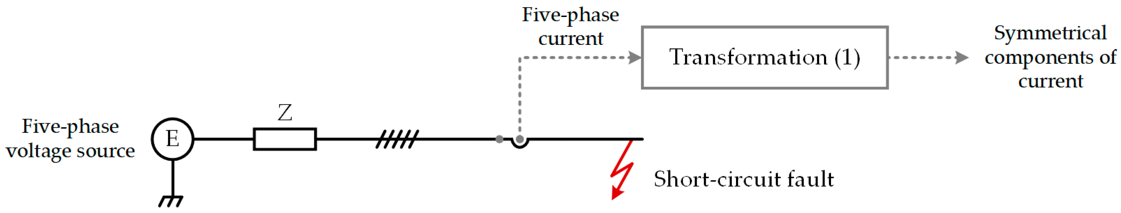
3. Investigation Methodology

As mentioned in the introduction, this study aimed to derive the symmetrical components of voltage and current for a five-phase electrical system and then to determine the sequence networks connections for several types of short-circuit faults, or more exactly, for the significant short-circuit faults. For a five-phase electrical system, the symmetrical components are obtained from the phase quantities by applying the transformation given in Equation (1), where χ designates either the phase voltage or the current, each of the subscripts 0, 1, 2, 3, 4 denote one of the five symmetrical components and each of the subscripts A, B, C, D, E denote one of the five phase quantities [30].
[ χ 0 χ 1 χ 2 χ 3 χ 4 ] = 1 5 [ 1 1 1 1 1 1 α α 2 α 3 α 4 1 α 2 α 4 α α 3 1 α 3 α α 4 α 2 1 α 4 α 3 α 2 α ] [ χ A χ B χ C χ D χ E ]
In Equation (1), as in the rest of this paper, the symmetrical components are referred to phase A. α is the phasor rotation operator given in Equation (2), which rotates a phasor counterclockwise by 72° (360° divided by 5, the number of phases in a five-phase electrical system) when multiplied by it [27]. It also satisfies the mathematical relation given in Equation (3), which is used later in this paper.
α = 1 72 ° = e j 72 °
1 + α + α 2 + α 3 + α 4 = 0
The inverse transformation to obtain the phase quantities from the symmetrical components is given in Equation (4) and can be applied to both voltage and current quantities [30].
[ χ A χ B χ C χ D χ E ] = [ 1 1 1 1 1 1 α 4 α 3 α 2 α 1 α 3 α α 4 α 2 1 α 2 α 4 α α 3 1 a α 2 α 3 α 4 ] [ χ 0 χ 1 χ 2 χ 3 χ 4 ]
Ohm’s law correlates the symmetrical components of voltages and currents in the same way it correlates their phase counterparts, hence, the sequence impedances can be defined using Equation (5), where Vq and Iq are the symmetrical components of voltage and current, and Zq is their equivalent sequence impedance.
Z q = V q I q ,           q = 0 , 1 , 2 , 3 , 4
As in the balanced three-phase systems, in balanced five-phase systems, the sequence networks are decoupled, but under unbalanced conditions, such as with short-circuit faults, these networks become connected in a fault-dependent manner [26]. Precisely the manner in which the sequence networks are connected for the significant short-circuit faults is investigated onwards in this paper. For this, the following investigation methodology is applied:
step 1: write the boundary conditions for the selected type of short-circuit fault assuming no load conditions;
step 2: derive the symmetrical components of voltage and/or current at fault location, as well as the relevant relationships between them;
step 3: determine the mathematical constraints imposed on the sequence networks connections by the selected fault;
step 4: draw the equivalent sequence networks connections diagram based on the mathematical constraints previously determined;
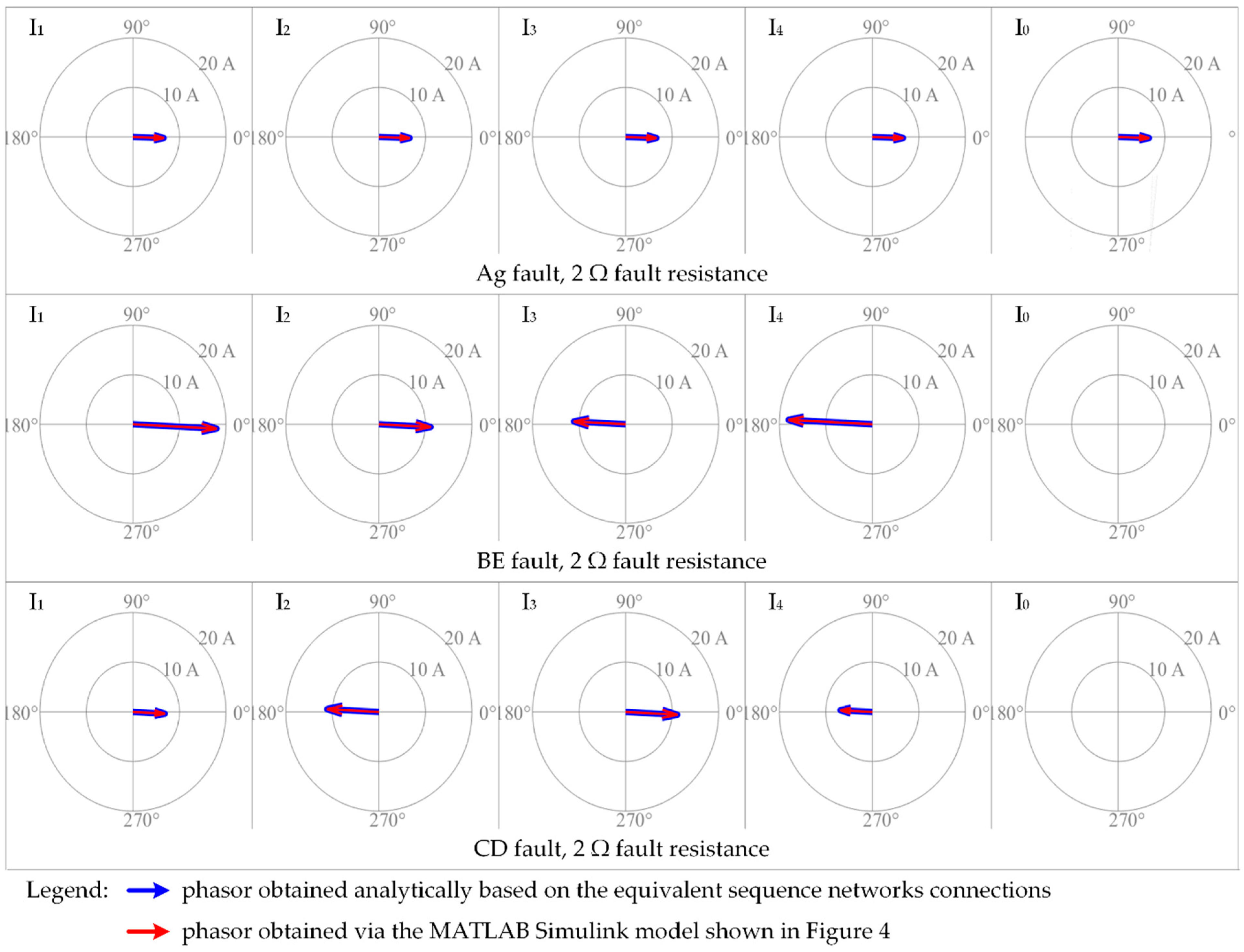
step 5: check the obtained results using computer simulations.

4. Short-Circuit Analysis in Five-Phase AC Systems

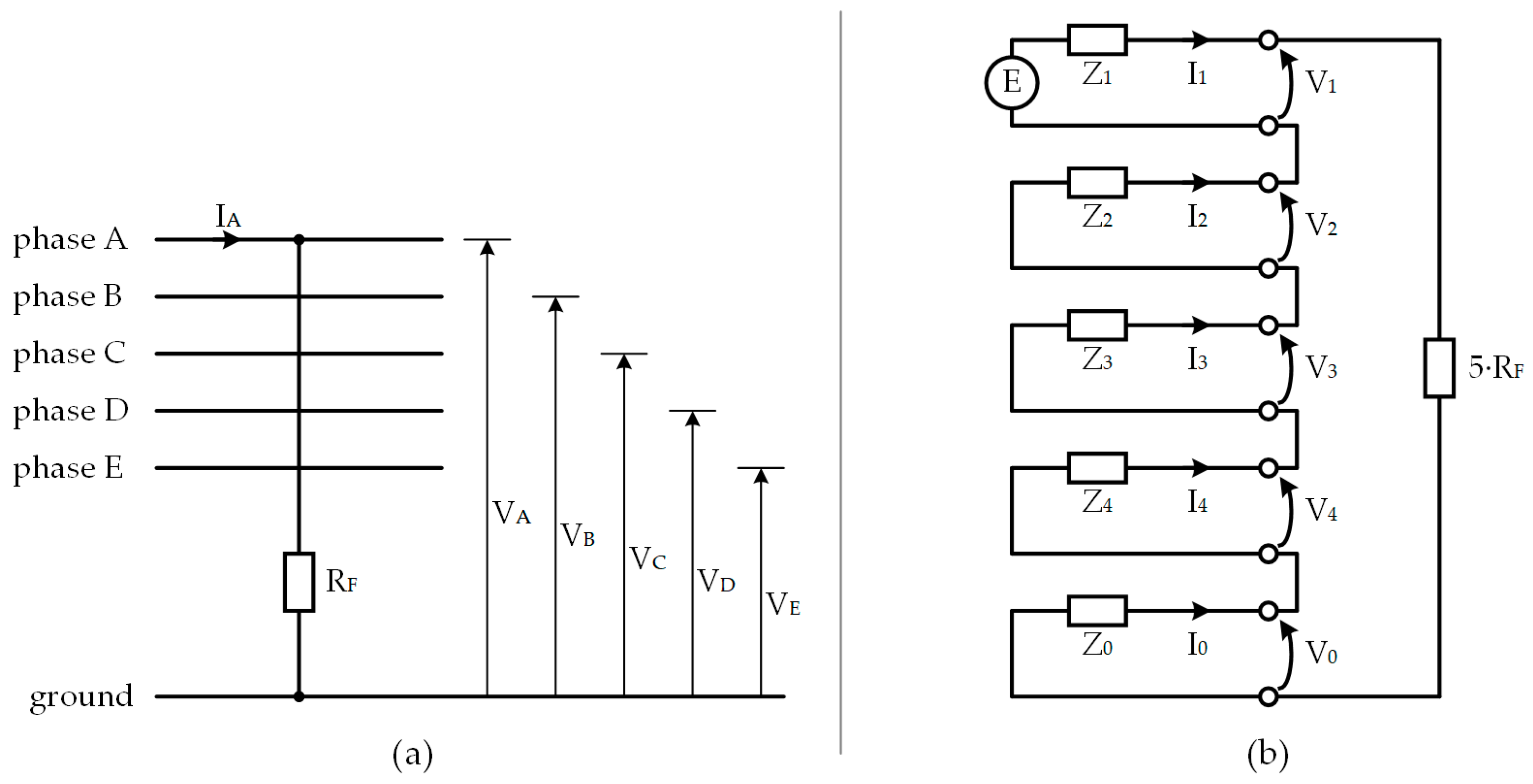
4.1. Single-Phase-to-Ground Fault

The Ag fault is the significant short-circuit for single-phase-to-ground faults and is characterized by the boundary conditions given in Equation (6), where RF is the fault resistance, i.e., the resistance between phase A and the ground.
{ I B = I C = I D = I E = 0 V A = R F I A
The symmetrical components of the fault current are then derived in Equation (7) using the boundary condition for currents and Equation (1). Relation Equation (7) shows that the fault current IA is in-phase with I1, this is also the case with the other symmetrical components in which IA decomposes.
I 0 = I 1 = I 2 = I 3 = I 4 = 1 5 I A
The boundary condition for voltage is used together with Equation (4) to obtain Equation (8).
V 0 + V 1 + V 2 + V 3 + V 4 = R F I A
Relation Equation (8) is then rewritten as in Equation (9) using the current relationships from (7).
V 0 + V 1 + V 2 + V 3 + V 4 = 5 R F I 0
Relations Equations (7) and (9) represent the mathematical constraints imposed on the sequence networks connections by the Ag fault and on the basis of which the sequence networks connections for this type of fault are drawn. From the constraints, it is obvious that the sequence networks are connected in series for an Ag fault, as shown in Figure 1b, where E represents the e.m.f of the five-phase network, and Z0, Z1, Z2, Z3, Z4 are its equivalent sequence impedances. Figure 1a shows the five-phase electrical network with an Ag short-circuit.
Finally, the fault current IA is expressed in Equation (10) on the basis of the sequence networks diagram shown in Figure 1b.
I A = 5 I 1 = 5 E Z 0 + Z 1 + Z 2 + Z 3 + Z 4 + 5 R F

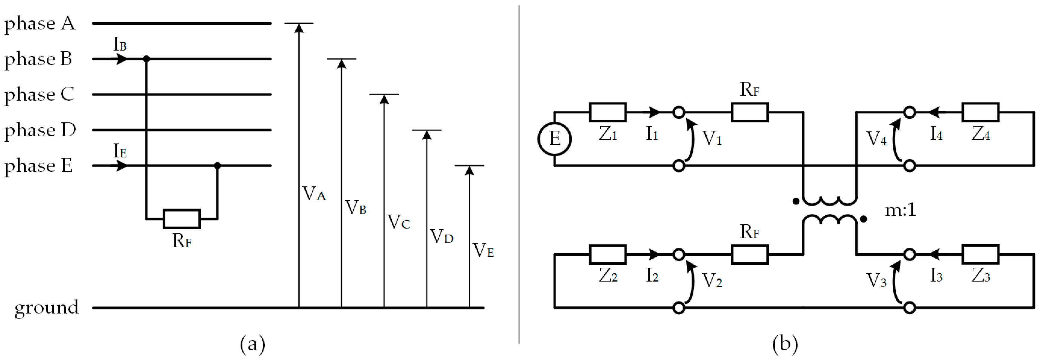
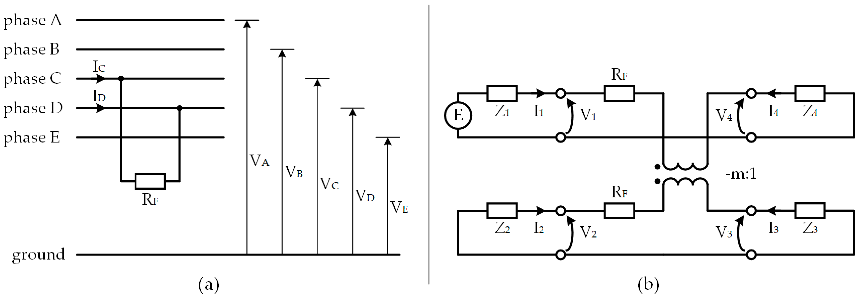
4.2. Two-Phase Faults

The BE fault and the CD fault are the significant short-circuits for the two-phase faults that may occur in five-phase electrical systems, and both are analyzed below.
BE fault
The boundary conditions for the BE fault are given in Equation (11), where RF is the fault resistance, i.e., the resistance between phase B and phase E.
{ I E = I B I A = I C = I D = 0 V B V E = R F I B
The symmetrical components of the short-circuit currents are derived in Equation (12) using the boundary conditions for currents and the transformation Equation (1), whereas the boundary condition for voltages is used together with the inverse transformation Equation (4) to obtain relation Equation (13).
{ I 0 = 0 I 1 = 1 5 I B ( α α 4 ) I 2 = 1 5 I B ( α 2 α 3 ) I 3 = 1 5 I B ( α 3 α 2 ) I 4 = 1 5 I B ( α 4 α )
V 1 ( α 4 α ) + V 2 ( α 3 α 2 ) + V 3 ( α 2 α 3 ) + V 4 ( α α 4 ) = R F I B
Using Equations (4) and (12), IB can be expressed as given in Equation (14).
I B = I 1 ( α 4 α ) + I 2 ( α 3 α 2 )
IB is then replaced in Equation (13) with its expression from Equation (14), thus obtaining, after some rearrangements, the relation (15).
( V 1 V 4 ) ( α 4 α ) + ( V 2 V 3 ) ( α 3 α 2 ) = R F I 1 ( α 4 α ) + R F I 2 ( α 3 α 2 )
By further refining relations Equations (12) and (15), the mathematical constraints imposed on the sequence networks connections by the BE fault are obtained in Equation (16), where m is the expression given in Equation (17), whose numerical value is in fact a real number.
{ I 2 = m I 1 I 3 = I 2 I 4 = I 1 V 1 V 4 R F I 1 = m ( V 3 V 2 + R F I 2 )
m = α 2 α 3 α α 4 0.618
The inspection of these constraints indicates that for a BE fault, the sequence networks of a five-phase electrical network are connected as shown in Figure 2b. Again, E represents the equivalent e.m.f of the five-phase system, shown in Figure 2a, and Z0, Z1, Z2, Z3, Z4 are its sequence impedances.
As seen in Figure 2b, I1 and I4, and I2 and I3, are the primary and the secondary winding currents of an ideal transformer, respectively, with a turns-ratio of m:1 (m ≅ 0.618), with I1 in opposition to I4, and I2 in opposition to I3. The polarity of this ideal transformer, indicated in Figure 2b using a dot convention, ensures that all the constraints given in (16) are met by the depicted sequence networks diagram for a five-phase system under a BE fault.
Based on the diagram shown in Figure 2b, I1 can be written as given in Equation (18).
I 1 = E Z 1 + Z 4 + R F + m 2 ( Z 2 + Z 3 + R F )
By replacing in Equation (14) the current I2 with its expression from Equation (16), the fault current IB can be rewritten as a function of I1 only, with the final result given in Equation (19).
I B = 5 ( α α 4 ) I 1 2.6287 j I 1
This result reveals that the fault current is in quadrature with its symmetrical component I1 and that it is sufficient to calculate I1 to determine IB. Of course, IB can also be expressed as a function of I2, I3, or I4, if desired, and according to Equation (16), IB is in quadrature with these currents as well.
From Equations (18) and (19), the expression Equation (20) is obtained for the fault current IB.
I B 2.6287 j E Z 1 + Z 4 + R F + 0.382 ( Z 2 + Z 3 + R F )
CD fault
The boundary conditions for the CD fault are given in Equation (21), where RF is the fault resistance, i.e., the resistance between phase C and phase D.
{ I D = I C I A = I B = I E = 0 V C V D = R F I C
Following the same methodology as for the previous type of fault, the symmetrical components of the fault currents are obtained in Equation (22).
{ I 0 = 0 I 1 = 1 5 I C ( α 2 α 3 ) I 2 = 1 5 I C ( α 4 α ) I 3 = 1 5 I C ( α α 4 ) I 4 = 1 5 I C ( α 3 α 2 )
The symmetrical components of the voltage at the fault location satisfy relation Equation (23), which is derived from Equation (4) and the last equation of Equation (21).
V 1 ( α 3 α 2 ) + V 2 ( α α 4 ) + V 3 ( α 4 α ) + V 4 ( α 2 α 3 ) = R F I C
Using Equations (4) and (22), IC can be expressed as given in Equation (24).
I C = I 1 ( α 3 α 2 ) + I 2 ( α α 4 )
IC is replaced in Equation (23) with its expression from Equation (24) and, after some rearrangements, the relation Equation (25) is obtained.
( V 1 V 4 ) ( α 3 α 2 ) + ( V 2 V 3 ) ( α α 4 ) = R F I 1 ( α 3 α 2 ) + R F I 2 ( α α 4 )
After further refinement of Equations (22) and (25), the mathematical constraints imposed on the sequence networks connections by the CD fault are obtained in Equation (26), where m is given in Equation (27).
{ I 2 = m I 1 I 3 = I 2 I 4 = I 1 V 1 V 4 R F I 1 = m ( V 3 V 2 + R F I 2 )
m = α α 4 α 3 α 2 1.618
The set of constraints Equation (26), corresponding to a CD fault, is the same as the set of constraints Equation (16), which corresponds to a BE fault. However, these two faults are not identical because the value of m differs between them, as Equations (17) and (27) reveal. As such, their equivalent sequence networks diagrams are also not identical.
The equivalent sequence networks diagram for a CD fault is shown in Figure 3b and, as can be observed, differs from the diagram of the BE fault only by a different transformer. Indeed, the ideal transformer involved in the equivalent sequence networks diagram of the CD fault has a turns-ratio of -m:1 (m ≅ −1.618) and opposite polarity for its secondary winding compared to the ideal transformer associated with the BE fault. All the constraints given in Equation (26) are satisfied by the sequence networks connections diagram shown in Figure 3b.
Based on the diagram shown in Figure 3b, I1 can be written as given in Equation (28).
I 1 = E Z 1 + Z 4 + R F + m 2 ( Z 2 + Z 3 + R F )
By replacing I2 in Equation (24) with its expression from Equation (26), the fault current IC can be calculated as a function of I1 only, with the final result given in (29).
I C = I 1 ( α 3 α 2 ) + m I 1 ( α α 4 ) 4.2533 j I 1
This result reveals that for a CD fault too, the fault current is in quadrature with its symmetrical component I1, as well as with I2, I3, and I4. Moreover, it is sufficient to calculate I1 to determine IC.
From Equations (28) and (29), the expression Equation (30) is obtained for the fault current IC.
I C = 4.2533 j E Z 1 + Z 4 + R F + 2.618 ( Z 2 + Z 3 + R F )

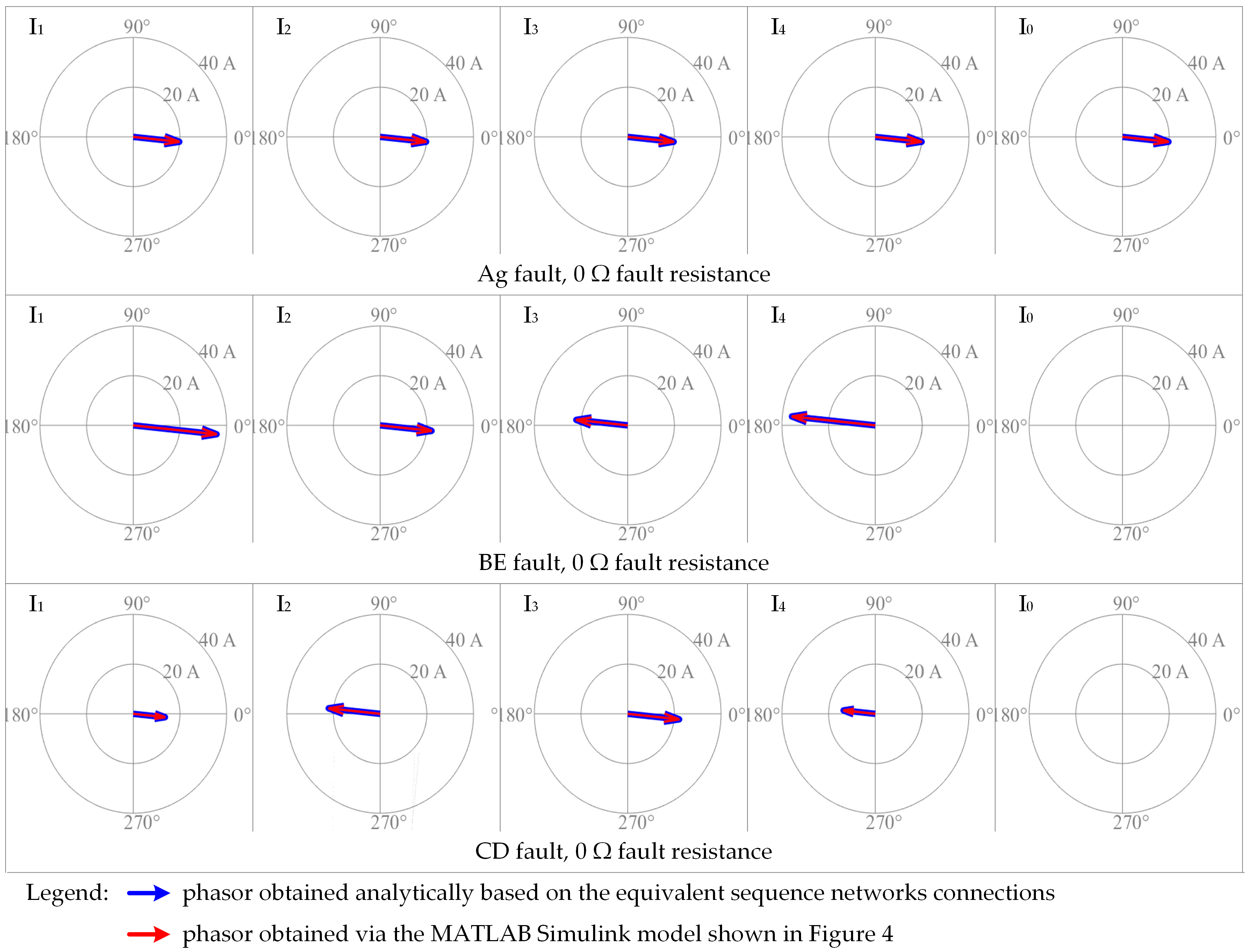
5. Simulation Results

The analytical results obtained in the previous section were verified using computer simulations, this being the last step of the investigation methodology applied in this study. For this, a five-phase electrical system was implemented in MATLAB Simulink so that short-circuit faults could be applied to it, as shown in Figure 4. The phase currents were measured at the fault location and their symmetrical components were computed using relation Equation (1). The five-phase voltage system was generated by an ideal source with the phase voltage E = 100 V, star-connected, and with the star-point directly grounded. The impedance on each phase of this electrical system was Z = 1 + j × 0.1 Ω and there was no coupling between phases, and between phases and ground, so Z1 = Z2 = Z3 = Z4 = Z0 = Z.
Several short-circuit conditions were simulated, covering single-phase-to-ground and two-phase faults with different fault resistances Rf. For each fault, the symmetrical components of the current given by the described MATLAB Simulink model were compared with the symmetrical components given by the equivalent sequence networks diagram determined previously in this paper. Figure 5 and Figure 6 present the symmetrical components of the current for Ag, BE, and CD faults, for Rf = 0 Ω and for Rf = 2 Ω, respectively. As can be seen in both figures, there is virtually no difference between the phasors obtained using the MATLAB Simulink model and those obtained analytically using the short-circuit analysis and the equivalent sequence networks connections of the five-phase system.
In the case of Ag faults, regardless of the fault resistance, I1 = I2 = I3 = I4 = I0. In the case of BE and CD faults, regardless of the fault resistance, I1 = I4, I3 = I4, I0 = 0 and I2 = m·I1, with m ≅ 0.618 for BE faults and m ≅ 1.618 for CD faults. Again, these results were observed both for the phasors obtained by simulations and for those obtained analytically. Because the relationships between the symmetrical components of the fault current are independent of the fault resistance but depend on the fault type, they can be used in practice for the classification of short-circuit faults in a five-phase electrical system. Accordingly, a protection system could first detect a short-circuit fault by detecting that a symmetrical component, such as I2, has exceeded a predefined threshold value, and then it could identify the type of fault by comparing the numerical values of I1, I2, I3, I4 and I0, and by establishing the relationships between these quantities.
The fault currents for the analyzed short-circuit conditions, the current on phase A for the Ag fault, the current on phase B for the BE fault, and the current on phase C for the CD fault are given in Figure 7. As can be seen, there is no difference between the fault currents obtained using the simulations and the fault currents obtained analytically, namely by using the Equations (10), (20), and (30), respectively.
The magnitude of the fault currents depends on the resistance of the fault and the type of fault. A lower value of the fault resistance obviously results in a higher magnitude of the fault current, as shown in Figure 7 and by Equations (10), (20), and (30), as well as higher magnitudes of the symmetrical components of the fault current, as shown in Figure 5 and Figure 6. Nevertheless, the short-circuit analysis presented in this paper can be used to compute the fault currents and their symmetrical components for any value of the fault resistance, thus covering a wide range of fault conditions, from metallic faults to high-resistance faults. In addition, by appropriately selecting the fault resistance, one can also capture the evolution of a short-circuit fault which in the incipient stage has a high resistance, but over time develops into a metallic fault. Regarding the dependence of the magnitude of the fault current on the type of fault, the most interesting result is that for the five-phase electrical system implemented in MATLAB Simulink for this paper, the BE faults cause higher fault currents than the CD faults. This result is in accordance with the results predicted by Equations (20) and (30) for Z1 = Z2 = Z3 = Z4 = Z0, which are in fact the impedance parameters of the five-phase network that has been simulated.
All these results practically validate the short-circuit analysis and the equivalent sequence networks connections derived in the previous section of this paper for single-phase-to-ground and two-phase short-circuit faults occurring in a five-phase electrical system. The analytical results are thus confirmed by computer simulations, this being the last step, i.e., the methodological step 5, of the conducted study.

6. Conclusions

Single-phase and three-phase systems are the most common and important type of AC systems, but multiphase AC systems with more than three phases are also used in some applications, although rarely and mostly for research or special purposes. Even though some technical papers discuss the analysis of multiphase systems using the Fortescue’s theorem, the literature is quite limited in regards to the method of symmetrical components applied to five-phase systems. Therefore, the author of this paper analytically derived the symmetrical components of voltage and current, as well as the equivalent sequence networks diagrams for several types of short-circuit faults that could occur in a five-phase AC system, focusing on those faults that are more likely to occur. The analytical results were verified and subsequently confirmed by computer simulations, and these results represent the main novelty or contribution of this this paper.
The relevance of this study is that it complements the existing literature on short-circuit analysis of multiphase electrical systems using the method of symmetrical components, which could be very relevant in the future with the development of five-phase drives, five-phase power transmission, and other five-phase applications. The possibility for future work remains and may advance in various directions, including the derivation of the equivalent sequence networks connections for other types of short-circuit faults, for combinations of faults or for other unbalanced network conditions, such as open-circuit faults, as well as the definition of phase imbalance factors for five-phase systems. Moreover, protection systems based on symmetrical components could be proposed for five-phase applications, and protection studies could be performed using this work. Ultimately, the method of symmetrical components could have the same applicability for five-phase electrical systems as for conventional three-phase electrical systems.

Funding

This research received no external funding.

Institutional Review Board Statement

Not applicable.

Informed Consent Statement

Not applicable.

Data Availability Statement

The study did not report any data.

Conflicts of Interest

The author declares no conflict of interest.

References

  1. Blalock, T.J. The first polyphase system. IEEE Power Energy Mag. 2004, 2, 63–66. [Google Scholar] [CrossRef]
  2. Sekhar, G.C.; Subramanyam, P.S. Protection of Six Phase Transmission system of Allegheny Power System, USA against shunt faults. In Proceedings of the 2014 International Conference on Smart Electric Grid (ISEG), Guntur, India, 19–20 September 2014. [Google Scholar]
  3. Mustafa, M.W.; Ahmad, M.R.; Shareef, H. Fault analysis on double three-phase to six-phase converted transmission line. In Proceedings of the 2005 International Power Engineering Conference, Singapore, 29 November–2 December 2005. [Google Scholar]
  4. Ciontea, C.I.; Iov, F. Propagation of voltage sags and under-voltages through Scott transformers. In Proceedings of the 2021 International Aegean Conference on Electrical Machines and Power Electronics (ACEMP) & 2021 International Conference on Optimization of Electrical and Electronic Equipment (OPTIM), Brasov, Romania, 2–4 September 2021. [Google Scholar]
  5. Abdel-Khalik, A.S.; Shafik, Z.; Elserougi, A.; Ahmed, S.; Massoud, A. A static three-phase to five-phase transformer based on Scott connection. Electr. Power Syst. Res. 2014, 110, 84–93. [Google Scholar] [CrossRef]
  6. Lanka, K.; Kambhampati, T.; Kumar, V.V.S.B.; Kalyan, M. Three-phase to five-phase transformation using a special transformer connection. Int. J. Appl. Res. Stud. 2012, 1, 1–11. [Google Scholar]
  7. Tabrez, M.; Sadhu, P.K.; Iqbal, A. A novel three phase to seven phase conversion technique using transformer winding connections. Eng. Technol. Appl. Sci. Res. 2017, 7, 1953–1961. [Google Scholar] [CrossRef]
  8. Moinoddin, S.; Iqbal, A.; Abu-Rub, H.; Khan, M.R.; Ahmed, S.M. Three-phase to seven-phase power converting transformer. IEEE Trans. Energy Convers. 2012, 27, 757–766. [Google Scholar] [CrossRef]
  9. Levi, E. Multiphase electric machines for variable-speed applications. IEEE Trans. Ind. Electron. 2008, 55, 1893–1909. [Google Scholar] [CrossRef]
  10. Cao, W.; Mecrow, B.C.; Atkinson, G.J.; Bennett, J.W.; Atkinson, D.J. Overview of electric motor technologies used for More Electric Aircraft (MEA). IEEE Trans. Ind. Electron. 2012, 59, 3523–3531. [Google Scholar]
  11. Hezzi, A.; Elghali, S.B.; Salem, Y.B. Control of five-phase PMSM for electric vehicle application. In Proceedings of the 18th International Conference on Sciences and Techniques of Automatic Control & Computer Engineering, Monastir, Tunisia, 21–23 December 2017. [Google Scholar]
  12. Hakeem, A.A.; Elserougi, A.; Abdel-Khalik, A.S.; Massoud, A.M. Performance of a five-phase boost inverter-fed submersible induction machine. In Proceedings of the 2013 International Electric Machines & Drives Conference, Chicago, IL, USA, 12–15 May 2013. [Google Scholar]
  13. Liu, H.; Wang, D.; Yi, X. Modeling and analytical calculation of a multiphase induction motor in the phase loss asymmetrical transient process. J. Electr. Eng. Technol. 2019, 14, 1269–1279. [Google Scholar] [CrossRef]
  14. Dabour, S.M.; Hassan, A.E.W.; Rashad, E.M. Five-phase induction motor drive system fed from five-phase matrix-converter. In Proceedings of the 15th International Middle East Power Systems Conference, Alexandria, Egypt, 23–25 December 2012. [Google Scholar]
  15. Riveros, J.A.; Barrero, F.; Levi, E.; Durán, M.J.; Jones, M. Variable-speed five-phase induction motor drive based on predictive torque control. IEEE Trans. Ind. Electron. 2013, 60, 2957–2968. [Google Scholar] [CrossRef]
  16. Gonçalves, P.; Cruz, S.; Mendes, A. Finite control set model predictive control of six-phase asymmetrical machines—An overview. Energies 2019, 24, 4693. [Google Scholar] [CrossRef] [Green Version]
  17. Che, H.S.; Levi, E.; Jones, M.; Duran, M.J.; Hew, W.P.; Rahim, N.A. Operation of a six-phase induction machine using series-connected machine-side converters. IEEE Trans. Ind. Electron. 2014, 61, 164–176. [Google Scholar] [CrossRef] [Green Version]
  18. Chinmaya, K.A.; Singh, G.K. An advanced disturbance reduction field-oriented control for six-phase induction machine. In Proceedings of the IEEMA Engineer Infinite Conference, New Delhi, India, 13–14 March 2018. [Google Scholar]
  19. Mengoni, M.; Zarri, L.; Rizzoli, G.; Tani, A.; Gritli, Y.; Duran, M.J. Use of field harmonics in multiphase induction motor drives for on-line parameter estimation. In Proceedings of the IEEE Workshop on Electrical Machines Design, Control and Diagnosis, Nottingham, UK, 20–21 April 2017. [Google Scholar]
  20. Liu, X.; Kong, W.; Qu, R.; Xu, Q. Non-sinusoidal power supply technology based on space vector PWM for multiphase variable speed drives. In Proceedings of the IEEE Energy Conversion Congress and Exposition, Portland, OR, USA, 23–27 September 2018. [Google Scholar]
  21. Umesh, B.S.; Sivakumar, K. Multilevel inverter scheme for performance improvement of pole-phase-modulated Multiphase induction motor drive. IEEE Trans. Ind. Electron. 2016, 63, 2036–2043. [Google Scholar] [CrossRef]
  22. Levi, E.; Bojoi, R.; Profumo, F.; Toliyat, H.A.; Williamson, S. Multiphase induction motor drives—A technology status review. IET Electr. Power Appl. 2007, 1, 489–516. [Google Scholar] [CrossRef] [Green Version]
  23. Levi, E. Advances in converter control and innovative exploitation of additional degrees of freedom for multiphase machines. IEEE Trans. Ind. Electron. 2016, 63, 433–448. [Google Scholar] [CrossRef] [Green Version]
  24. Fortescue, C.L. Method of symmetrical co-ordinates applied to the solution of polyphase networks. In Proceedings of the 34th Annual Convention of the American Institute of Electrical Engineers, Atlantic City, NJ, USA, 19–22 June 1918. [Google Scholar]
  25. Chicco, G.; Mazza, A. 100 years of symmetrical components. Energies 2019, 12, 450. [Google Scholar] [CrossRef] [Green Version]
  26. Arafat, A.K.M.; Choi, S.; Baek, J. Open-phase fault detection of a five-phase permanent magnet assisted synchronous reluctance motor based on symmetrical components theory. IEEE Trans. Ind. 2017, 64, 6465–6474. [Google Scholar] [CrossRef]
  27. Kulkarni, S.; Parit, A.B.; Pulavarthi, B.; Patil, S.S. Comparative analysis of three phase, five phase and six phase symmetrical components with Matlab. In Proceedings of the International Conference on Data Management, Analytics and Innovation, Pune, India, 24–26 February 2017. [Google Scholar]
  28. Al-Turkki, Y.A. Symmetrical component representation of a six-phase salient-pole machine. J. King Saud Univ.-Eng. Sci. 1993, 5, 17–30. [Google Scholar] [CrossRef]
  29. Gökalp, E.; Tercan, S.M. Fault analysis in multi-phase power systems considering symmetrical components and chase coordinates methods. J. Eng. Technol. 2019, 3, 41–59. [Google Scholar]
  30. Prasad Rao, K.P.; Kavya, P.; Sai Kalyan, P. Fault analysis of five phase transmission system. J. Electr. Eng. 2017, 17, 8. [Google Scholar]
  31. Bhatt, N.B.; Venkata, S.S.; Guyker, W.C.; Booth, W.H. Six-phase (multi-phase) power transmission systems: Fault analysis. IEEE Trans. Power Appar. Syst. 1977, PAS-96, 758–767. [Google Scholar] [CrossRef]
  32. Abu-Elhaija, W.S.; Amoura, F.K. Fault analysis of six phase power system using six phase symmetrical components. Electr. Power Compon. Syst. 2006, 33, 657–671. [Google Scholar] [CrossRef]
  33. Ciontea, C.I. The use of symmetrical components in electrical protection. In Proceedings of the 72nd Conference for Protective Relay Engineers, College Station, TX, USA, 25–28 March 2019. [Google Scholar]
  34. Ciontea, C.I.; Iov, F. A study of load imbalance influence on power quality assessment for distribution networks. Electricity 2021, 2, 77–90. [Google Scholar] [CrossRef]
  35. Pierre, B.J. High phase order transmission line fault types. Electr. Power Compon. Syst. 2019, 47, 1667–1676. [Google Scholar] [CrossRef] [Green Version]
  36. Blackburn, J.L. Symmetrical Components for Power Systems Engineering; Marcel Dekker Inc.: New York, NY, USA, 1993. [Google Scholar]
Figure 1. Ag fault: (a) the five-phase system and (b) sequence networks connections.
Electricity 03 00015 g001
Figure 2. BE fault: (a) the five-phase system and (b) sequence networks connections.
Electricity 03 00015 g002
Figure 3. CD fault: (a) the five-phase system and (b) sequence networks connections.
Electricity 03 00015 g003
Figure 4. MATLAB Simulink model of five-phase electrical system.
Electricity 03 00015 g004
Figure 5. Symmetrical components of current, denoted I1, I2, I3, I4, I0, during Ag, BE, and CD faults for Rf = 0 Ω.
Electricity 03 00015 g005
Figure 6. Symmetrical components of current, denoted I1, I2, I3, I4, I0, during Ag, BE, and CD faults for Rf = 2 Ω.
Electricity 03 00015 g006
Figure 7. Fault currents during Ag, BE, and CD faults for Rf = 0 Ω and for Rf = 2 Ω.
Electricity 03 00015 g007
Table 1. Classification of short-circuit faults for three-phase and five-phase electrical systems.
Fault TypeShort-Circuit Faults in
Three-Phase Systems
Short-Circuit Faults in
Five-Phase Systems
Single-phase-to-groundAg, Bg, CgAg, Bg, Cg, Dg, Eg
Two-phase-to-groundABg, ACg, BCgABg, ACg, ADg, AEg, BCg, BDg, BEg, CDg, CEg, DEg
Two-phaseAB, AC, BCAB, AC, AD, AE, BC, BD, BE, CD, CE, DE
Three-phase-to-groundABCgABCg, ABDg, ABEg, ACDg, ACEg, ADEg, BCDg, BCEg, BDEg, CDEg
Three-phaseABCABC, ABD, ABE, ACD, ACE, ADE, BCD, BCE, BDE, CDE
Four-phase-to-ground-ABCDg, ABCEg, ABDEg, ACDEg, BCDEg
Four-phase-ABCD, ABCE, ABDE, ACDE,
BCDE
Five-phase-to-ground-ABCDEg
Five-phase-ABCDE
Total/significant faults11/557/13
Note: The significant short-circuit faults are written in bold.
Publisher’s Note: MDPI stays neutral with regard to jurisdictional claims in published maps and institutional affiliations.

