1. Introduction
The advancement of micro actuators plays a crucial role in various fields, from robotics to precision manufacturing. The focus of this project is to design and optimize a micro actuator with high resolution and reliability. Specifically, the objective is to develop a micro actuator with a resolution of 1 micron or less and an actuation length of 20 mm. To achieve this, a stepper motor has been selected for actuation, owing to its ability to maintain position with minimal power consumption, aligning with industry sustainability goals. The project also emphasizes a factor of safety greater than 15, ensuring reliability and robustness in various applications. Also, various gears are used and tested to find the optimal gear type for the actuator. Design life analysis will also be performed along with the eco-audit of our prototype.
2. Literature Review
Various actuation principles, such as thermal actuation, electrostatic actuation, electromagnetic actuation, pneumatic actuation, and hydrostatic actuation, are theoretical aspects of actuation technologies only, and are not sufficiently explored in the engineering-oriented literature. We found that there is a significant lack of information on controlling the actuation motion [
1,
2]. We had to disregard many papers on the basis that some of the technologies presented relied on the thermal expansion of substances, which is not suitable for our application. None of them had a solution for our problem of maintaining a certain actuation position without actively consuming any energy; however, the challenge at hand and the limitations we have with different actuation technologies and principles thus help us to move in right direction while finalizing the actuation principles for our actuator [
3].
3. Limitations in Existing Micro Actuators
The major challenge at hand is creating a micro actuator which can provide adequate force, the required travel range, extreme precision, and can hold a position indefinitely without actively consuming any energy. We will have to devise a mechanism and a miniature module controlling from scratch.
4. Gaps in the Literature
There is a significant lack of any literature that talks about micro actuation that is energy efficient in maintaining a specific position and can be precisely controlled. The existing literature on micro actuation talks only about the potential substances which deflect in the presence of electric currents, moisture gradients, or pneumatic pressure, but no reliable way to precisely control these actuation stimuli was presented in any of the papers. Also, all of the research papers talked only about the theoretical potential of several substances which can perform actuation and all those techniques had a significant shortcoming, that they had an extremely small travel range and also had an inadequate actuation force. So, the major challenge at hand is creating a micro actuator which can provide adequate force, the required travel range, extreme precision, and can hold a position indefinitely without actively consuming any energy. This still remains unanswered by the current available literature. As such, we will have to devise and test such a mechanism and a miniature controlling module from scratch.
To sum up, the gaps in the literature are as follows:
- -
Lack of proof of concept.
- -
Lack of controlling mechanism.
- -
Lack of required travel and actuation force.
- -
Lack of precise actuation motion.
- -
Lack of ability to hold a particular position.
- -
Lack of data on fatigue life and sustainability.
5. Motivation
To improve the physical characteristics and functionality of micro actuators in the current market and to reduce the manufacturing cost.
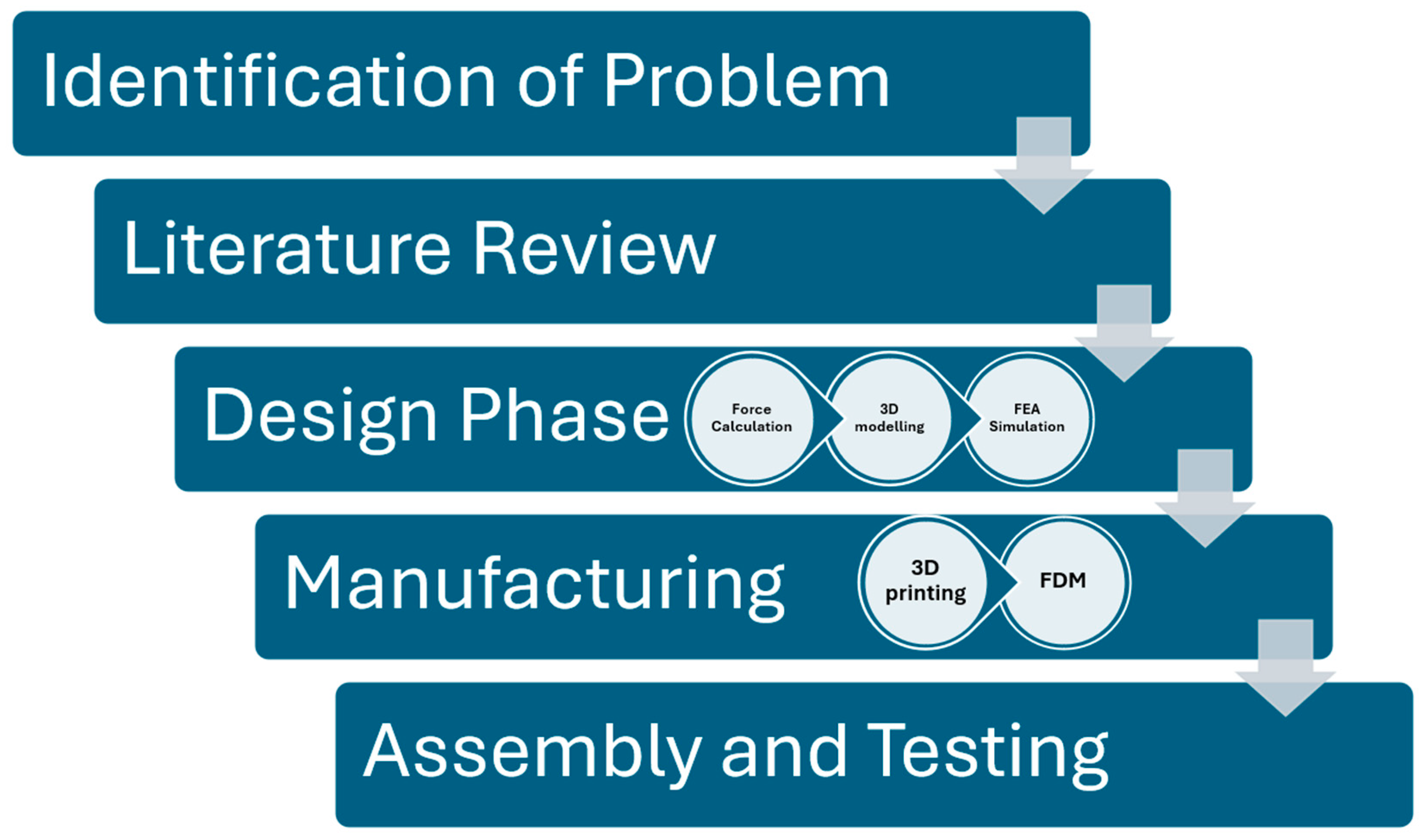
6. Methodology
The process we followed to successfully complete the work is explained using the flow chart in
Figure 1.
7. Justification of Gear Selection
Since we are going to perform additive manufacturing for the gears, we believe that spur gears are the best choice. Additive manufacturing, like 3D printing, allows us to fabricate simple geometries like spur gears with precision and at a lower cost, especially for micro-scale applications. The straightforward design of spur gears is perfect for this method, reducing the complexity of printing fine details. We will use Poly-Lactic Acid (PLA) as the material.
8. Material Selection and Justification
The actuator components were manufactured using the Fused Deposition Modelling (FDM) method of additive manufacturing. The material used in Polylactic Acid (PLA) is more rigid as compared to other material options (ABS, Nylon). PLA is also biodegradable, which is more environmentally sustainable, especially for mass production. PLA also has minimal shrinkage and warpage compared to ABS, which allows for better tolerances. Also, FDM is a faster manufacturing process as compared to DLP, which makes it suitable for rapid prototyping. The printing parameters in FDM can be optimized, which can reduce material consumption and increase the strength of the component [
4,
5].
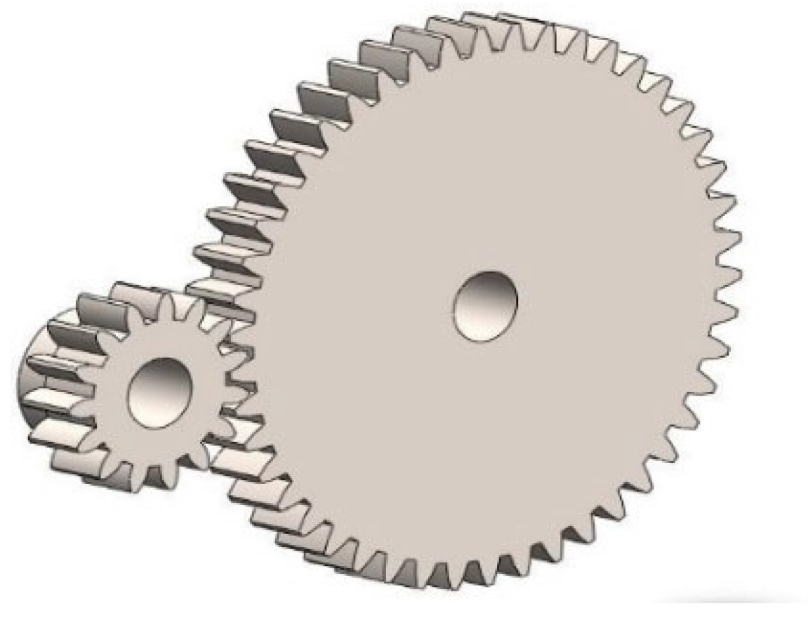
9. Gear Specification
The CAD images of both the spur gears and pinion used is shown in
Figure 2.
The specifications of Gear 1 and Gear 2 used in the study are mentioned in
Table 1 and
Table 2 respectively.
Gear Ratios:
(32/9), (33/22), (26/9), (31/10)
Multiplying the gear ratios:
(32/9) × (33/22) × (26/9) × (31/10) = 47.76296
After rounding up, this gives us an overall ratio of 48:1.
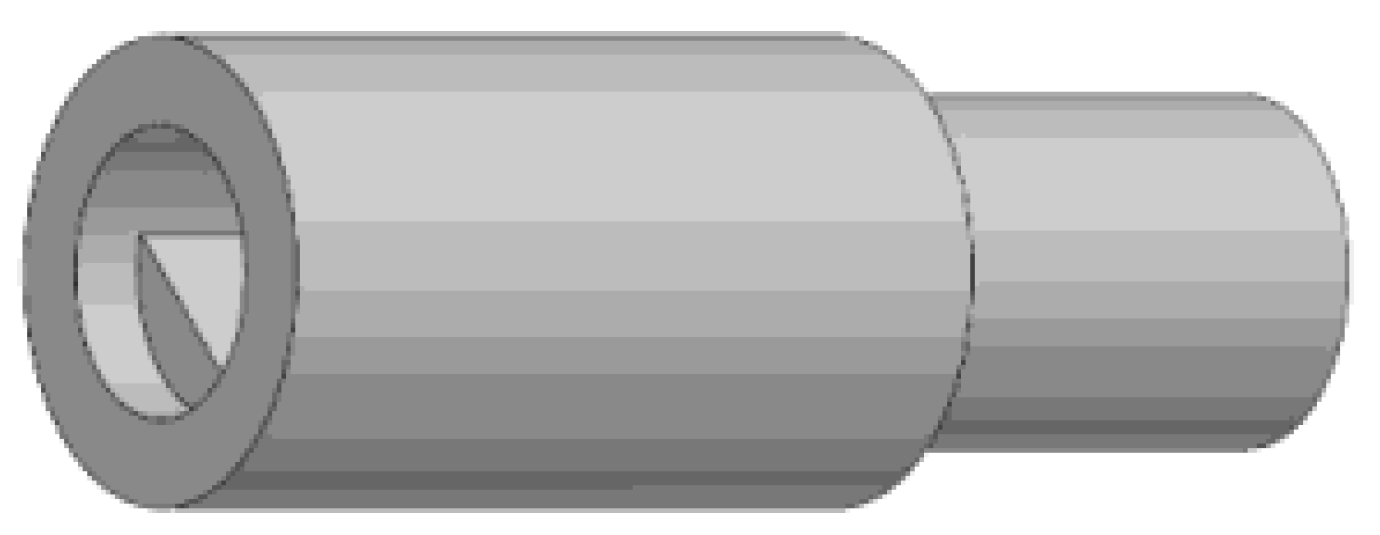
10. Lead Screw for Actuation
In this project, a trapezoidal thread for a lead screw is chosen because buttress threads can only be loaded in one direction. Furthermore, square threads are weaker at the root compared to trapezoidal threads, are difficult to manufacture, and hence more expensive than trapezoidal screws. We have selected the Single start T8 lead screw with pitch = 2 mm. The CAD image of the lead screw used is shown in
Figure 3.
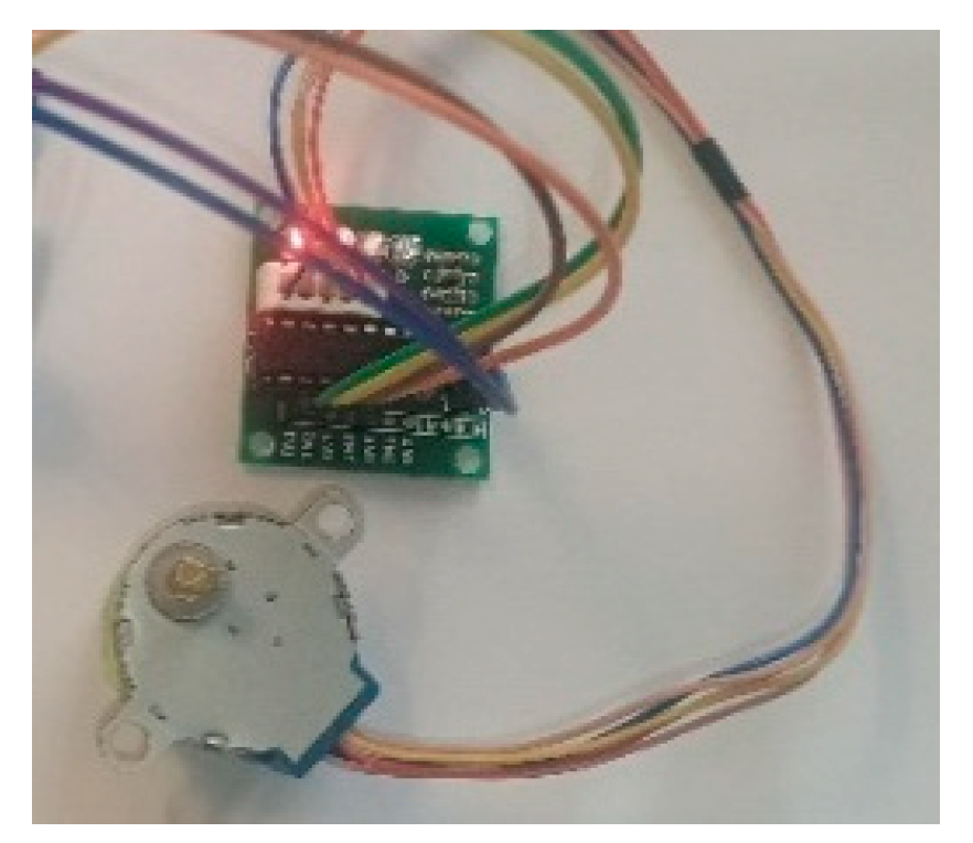
11. Stepper Motor Specifications
Specifications of the motor used are mentioned in
Table 3.
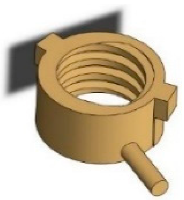
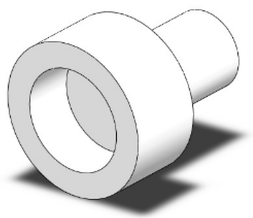
12. Lead Nut and Couplings
For the lead nut, we have selected the Single start T8 lead screw with a pitch of 2 mm. The threads are trapezoidal, matching the lead screw. An image of the stepper motor used is shown in
Figure 4 and the CAD images of the lead nut, 46 T Coupling, and 15 T Coupling are shown in
Figure 5,
Figure 6 and
Figure 7, respectively.
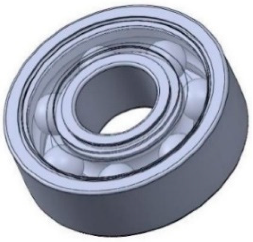
13. Bearing Selection
We have selected the SKF-6082RSH deep groove ball bearing (8 mm ID, 22 mm OD) for our micro actuator due to its cost-effectiveness and adequate performance with a limiting speed of 22,000 rpm. This bearing offers a reliable solution, handling both radial and axial loads effectively, making it ideal for our low-speed application. We opted against high-speed, specialized, or larger bearings, as they would introduce unnecessary complexity and costs without enhancing performance. Overall, the SKF-6082RSH ball bearing provides a perfect balance of reliability and affordability for the work. The CAD image of the bearing gears is shown in
Figure 8.
14. Base Body
The body has been designed to accommodate the lead screw with the bearings attached at both ends and has space for mounting the motors. The lead nut moves along the slot in the base body. The key slot prevents the lead nut itself from rotating along with the lead screw. The CAD image of the base body used is shown in
Figure 9.
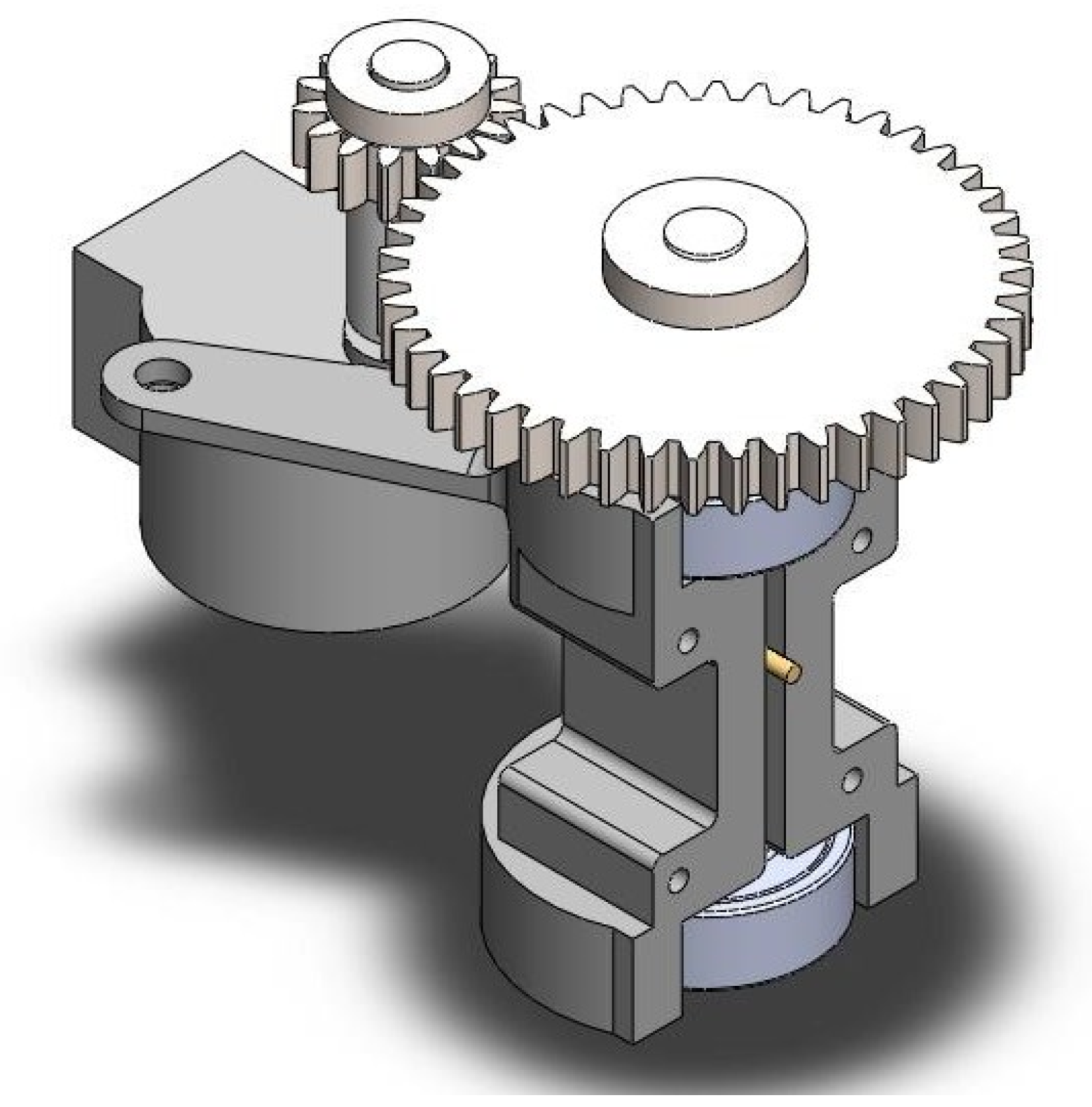
15. Final Assembly
The CAD image of the entire assembly of the micro actuator is shown in
Figure 10. The power is transferred from the motor to the pinion, then, from the pinion to the gear actuates in the lead nut to move in a micron.
16. Finite Element Analysis
Boundary conditions: the larger gear has been fixed, while remote displacement is provided to the smaller gear to simulate stress condition on the gear teeth, analyzing deformation in stress and strain as. shown in
Figure 11.
Factor of safety was calculated to be 15 using the Goodman Curve, as shown
Figure 12.
17. Market Study and Cost Analysis
North America is the leading producer and has the highest demand of micro actuators, followed by Europe. India has a relatively lower demand and less research in this field. South Asia is expected to experience a rise in demand of micro actuators because of the growth in the medical and healthcare industry due to rise in the ageing population. Most of the available micro actuators on the current market are as follows: Thermal Micro actuator, MEMS Micro actuator, Piezoelectric Micro Actuator, and Electrostatic Micro Actuator [
2]. The market price of the micro actuators mentioned above start from approximately
$80 (6900 Rs), as we have found from various online shopping websites and through market research. The bill of materials for the manufacturing of the micro actuator is mentioned in
Table 4.
18. Force Calculations
Pitch (lead); s is 2 mm, and efficiency; e is 0.4.
- (A)
Actuation Head Force
1. Torque at Stepper Motor Shaft (15 Teeth Gear Shaft): τ1 = 34.3 × 10⁻³ Nm
2. Torque at Lead Bolt Shaft (46 Teeth Gear Shaft): τ2 = Nm
3. Using Work-Energy Theorem (W.E.T):
4. Force Calculation: F =
F = 132.181 N ≈ 13.479 kgf
- (B)
Displacement of Actuation Head per Full Step of Stepper Motor
1. Motor steps per revolution = 2038
2. Angular Displacement of 15 Teeth Gear per Step: Δθ1
3. Angular Displacement of 46 Teeth Gear (Actuation Bolt): Δθ2
4. Lead per 360° Revolution of Actuation Bolt: Lead = 2 mm
5. Displacement per Step: x =
x = 0.320 × 10⁻³ mm = 0.320 μm
6. In Half-Stepping Mode: x = 0.16 μm
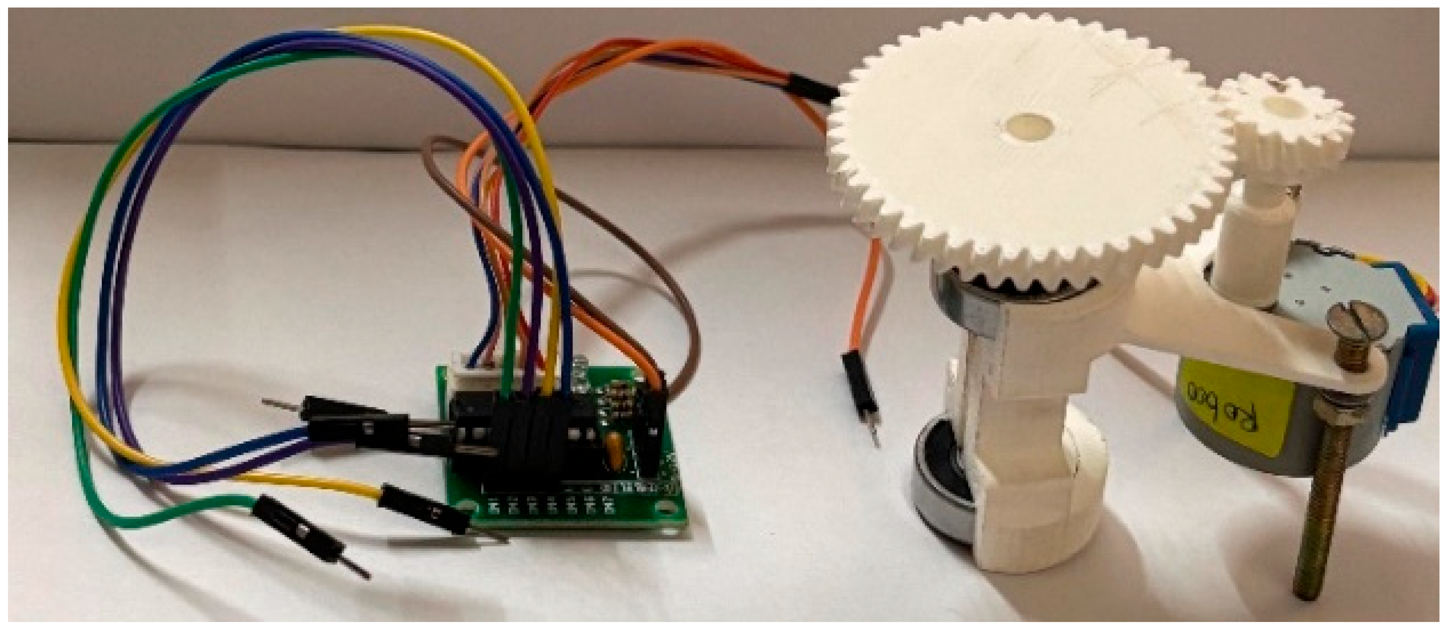
An image of all the 3D printed parts is shown in
Figure 13. An image of all the final assembly of the micro actuator is shown in
Figure 14.
19. Conclusions
In conclusion, the project was able to achieve the objectives of designing a high-precision and energy efficient micro actuator using sustainable materials at lower price. We achieved a resolution of 1 micron in actuator position, appropriately beneficial for precision application in biomedical and aerospace industries. The micro actuator can correctly integrate a stepper motor with spur gear reduction so that the actuator can hold position for any indefinitely long period without power consumption. It uses PLA material with FDM, a friendly and cheap manufacturing solution to the environment. Therefore, the study contributes to the field in demonstrating that FDM-printed, PLA-based actuators can meet such high-precision and durability requirements, further supporting the adoption of additive manufacturing in micro-electromechanical systems applications.
Author Contributions
Conceptualization, R.S.E.; methodology, R.S.E.; software, C.C.V.K.; validation, R.S.E. and N.S.; formal analysis, Y.T.; investigation, R.S.E.; resources, A.K.; data curation, A.K. and Y.T.; writing—original draft preparation, A.K., Y.T., R.S.E. and N.S.; writing—review and editing, R.S.E.; visualization, R.S.E.; supervision, R.S.E. and N.S.; project administration, R.S.E. and N.S. All authors have read and agreed to the published version of the manuscript.
Funding
This research was funded by VIT New Product Development Fund (Seed Funds).
Institutional Review Board Statement
Not applicable.
Informed Consent Statement
Not applicable.
Data Availability Statement
The data presented in this study are available upon request from the corresponding author.
Conflicts of Interest
The authors declare no conflict of interest.
References
- Pavan, B.G.; Sai Bhargav, M.; Harishesh, J.K.; Mamatha, A.S. Micro-Actuators and Implementation. arXiv 2022, arXiv:2212.13123v1. [Google Scholar] [CrossRef]
- Fujita, H.; Toshiyoshi, H. Micro actuators and their applications. Microelectron. J. 1998, 29, 637–640. [Google Scholar] [CrossRef]
- Ishihara, H.; Arai, F.; Fukuda, T. Micro mechatronics and micro actuators. IEEE/ASME Trans. Mechatron. 1996, 1, 68–79. [Google Scholar] [CrossRef]
- Müller, M.; Šleger, V.; Kolář, V.; Hromasová, M.; Piš, D.; Mishra, R.K. Low-Cycle Fatigue Behavior of 3D-Printed PLA Reinforced with Natural Filler. Polymers 2022, 14, 1301. [Google Scholar] [CrossRef] [PubMed]
- Abeykoon, C.; Sri-Amphorn, P.; Fernando, A. Optimization of fused deposition modeling parameters for improved PLA and ABS 3D printed structures. Int. J. Light. Mater. Manuf. 2020, 3, 284–297. [Google Scholar] [CrossRef]
| Disclaimer/Publisher’s Note: The statements, opinions and data contained in all publications are solely those of the individual author(s) and contributor(s) and not of MDPI and/or the editor(s). MDPI and/or the editor(s) disclaim responsibility for any injury to people or property resulting from any ideas, methods, instructions or products referred to in the content. |
© 2025 by the authors. Licensee MDPI, Basel, Switzerland. This article is an open access article distributed under the terms and conditions of the Creative Commons Attribution (CC BY) license (https://creativecommons.org/licenses/by/4.0/).


