Proceeding Paper

Performance Analysis of Double-Layered Thin-Walled Hemispherical Shell Structures Under Quasi-Static Compression †

by
Nalla Mohamed Mohamed Ismail
* and
Kavin Sudha Ramakrishnan
Department of Mechanical Engineering, Sri Sivasubramaniya Nadar College of Engineering, Kalavakkam 603110, India
*
Author to whom correspondence should be addressed.
Presented at the International Conference on Mechanical Engineering Design (ICMechD 2024), Chennai, India, 21–22 March 2024.
Eng. Proc. 2025, 93(1), 20; https://doi.org/10.3390/engproc2025093020
Published: 23 July 2025

Abstract

Thin-walled hemispherical shell structures are mainly used in the aerospace industry as energy absorbers. However, their thin walls frequently lead to stability problems. To create a stable structure, double-layered thin-walled hemispherical shell structures were developed. In this study, we investigated the deformation behaviors of these structures through both experimental and numerical methods. The shell span diameter is taken as 200 mm. Monolithic layers have thicknesses of 1.0 mm compared with double-layered shells which have thicknesses of 0.5 mm (inner)/0.5 mm (outer). We developed numerical models to simulate the structural responses of monolithic and double-layered spherical shell structures using ABAQUS/CAE® V6.14 software. These models were validated against experimental results. Our results show that double-layered shells absorb more energy compared to monolithic shells. These insights provide a foundation for improved designs of hemispherical structures, ultimately enhancing their energy absorption performance.

1. Introduction

In recent years, the application of multilayer metal protection shields has become increasingly widespread in many areas. Aluminum, one of the widely used metal products, has become a popular choice in many industries due to its lightweight, high strength, low cost, corrosion resistance, and fire resistance, which are the main features of research on protective coating [1,2,3,4,5]. However, current research on the crushing and impact resistance of aluminum alloys tends to focus on a single metal type. Based on the literature reviewed, it is clear that while single shells possess a strong capacity for energy absorption, their thin walls make them prone to stability issues. An effective alternative is the layering of shells which creates a robust protective structure [6,7,8]. While there are some studies on nested tubes and rings, there is a noticeable gap in research regarding the mechanical behavior of layered spherical shells which could exhibit interesting mechanical behaviors. In this study, we developed two designs: a monolithic (MSS) and a double-layered Hemispherical Shell System (DLS). We investigated the deformation behaviors of these structures using both experimental and numerical methods. The shell’s span diameter is 200 mm and includes multiple configurations. These configurations comprised monolithic layers with thicknesses of 0.5, 1, and 1.5 mm and double-layered options, such as having 0.5 mm layers on both the inside and outside, or 1.0 mm on the outside and 0.5 mm on the inside, and vice versa. We first developed numerical models to simulate the structural responses of monolithic spherical shell structures (MSS) using ABAQUS/CAE® software. These models were validated against experimental results. Moreover, we explored the effect of layering on enhancing the stability of monolithic shells. Additionally, parametric studies were conducted to examine how different shell geometrical configurations influence crushing resistance and energy absorption. Further details are presented in the following sections.

2. Experimental Methodology

In this paper, a compression test was first carried out by using a universal testing machine on monolithic and double-layered 1100 aluminum alloy spherical shells, respectively. Then, 3D finite element software (ABAQUS/Explicit software V6.14) was used to simulate the crushing processes in a specific working condition of the experiment. 1100-H12 aluminum sheet was purchased in standard thicknesses (0.5–1.5 mm). Tensile samples were extracted from the sheet to obtain the material properties. Uniaxial tensile experiments were performed to find the mechanical properties of the material [9]. The resulting data are shown in Figure 1 and are employed as a response for the performance of plastic strain curves in the FEM software by extracting the main points.
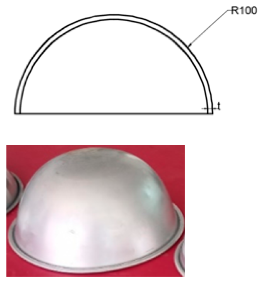
The sample geometry is shown in Figure 2, and the detailed dimensions are publicized in Table 1. To obtain a stable model, a two-layer hemispherical shell model is also designed. The double-layered hemispherical shell model (DLS) model has two hemispherical shells and is made of AA-1100H12 aluminum alloy. The details are shown in Table 1.

3. Numerical Methodology and Validation

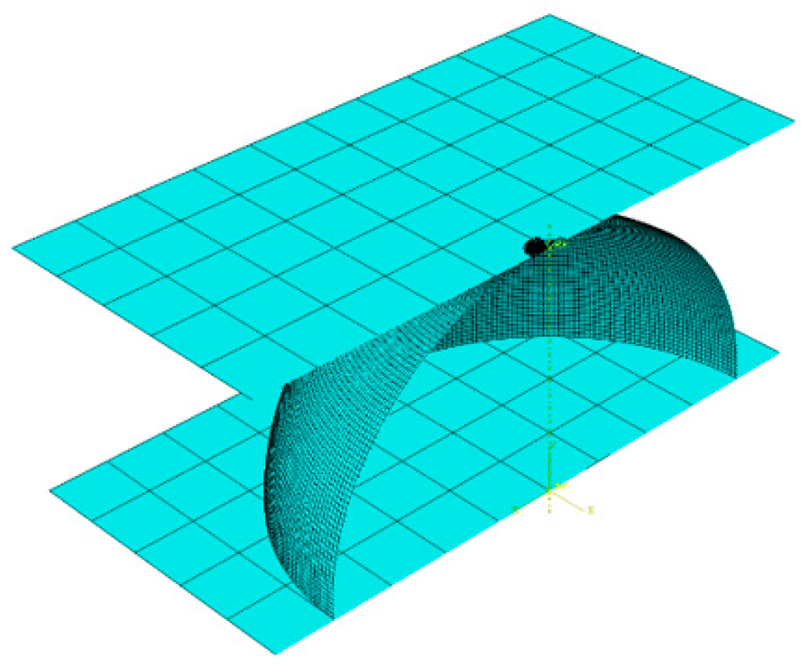
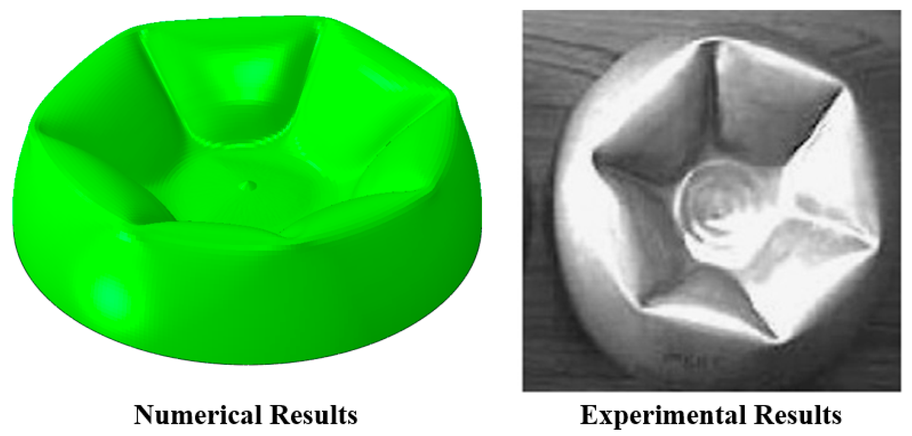
The collapse of monolithic and two-shell structures under quasi-static loading is simulated using the commercial finite element code ABAQUS explicit solver [10]. The finite element model consists of a deformable shell, an unrestrained stiff upper plate, and a rigid lower plate. Figure 3 shows the design model developed using ABAQUS® explicit coding. Four nodes quad shell elements were allotted for modeling a spherical shell. Rigid shell elements were allotted for the top and bottom plates. The mesh independence study was carried out for MSS to optimize the mesh size of the FE model. The optimum mesh size of 1 mm is suitable. Figure 4 demonstrates the buckled pattern of the hemispherical shell foreseen by finite element simulations and experimental observation.
Comparison of radius of parallel circle and EA of MSS specimen obtained through numerical procedure and validated by experimental results is tabulated in Table 2.

4. Results and Discussions

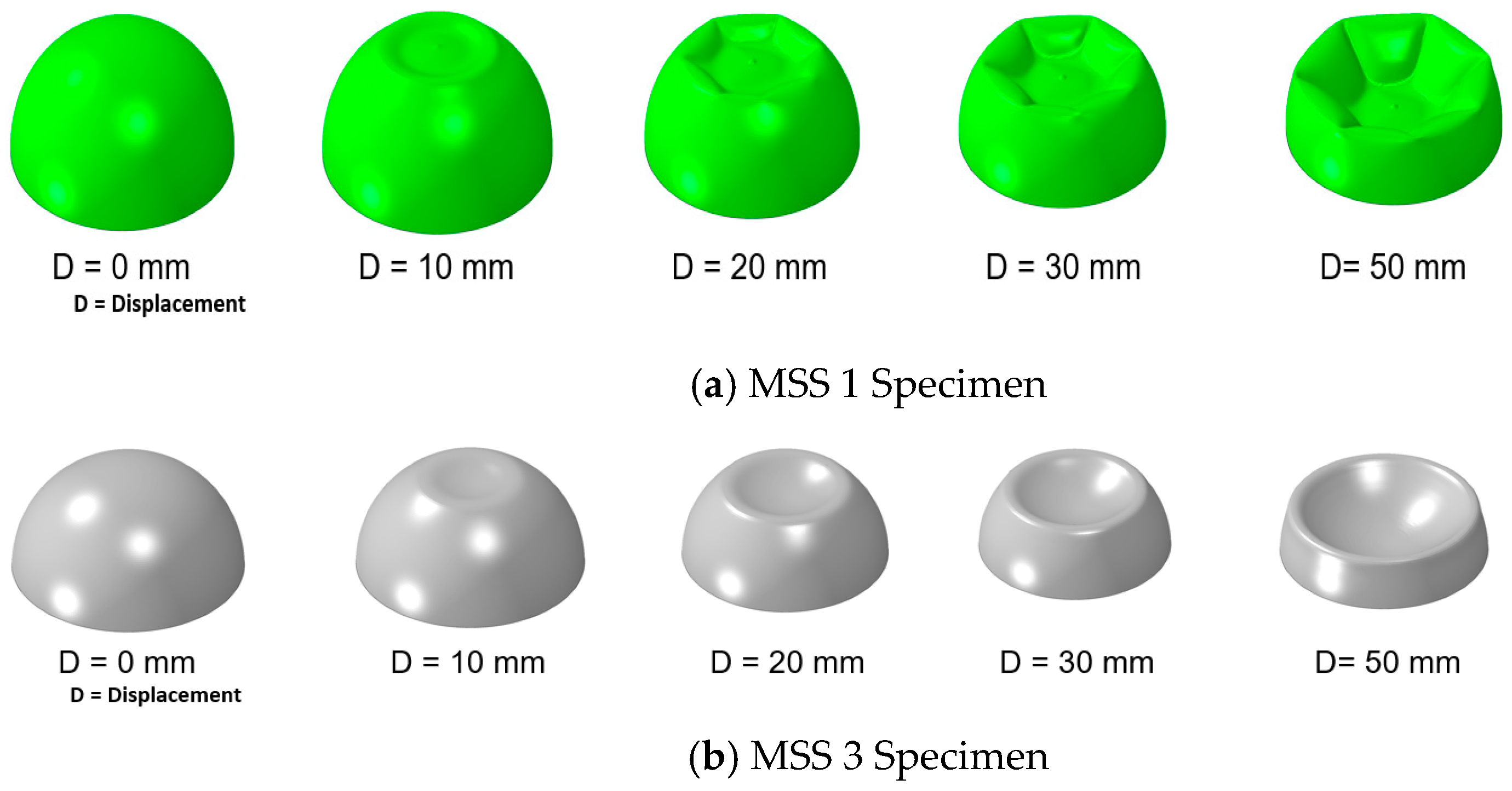
A comprehensive numerical analysis was performed on the axial crushing of monolithic (MSS), double layered hemispherical shells (DLS) structures under quasi-static loading. The samples were crushed up to half of their depth. Several types of failure [2] were detected which depend on the geometrical structures of the shells. Different methods of collapse such as flattening in local, dimpling internal, and development of unsymmetrical multiple number of sections were detected. Figure 5 shows the numerically expected buckle history of the ‘MSS 1’ and ‘MSS 3’ specimens at various stages of axial compression. It is perceived that in the early phase of crushing, the spherical shells buckled with a flat contact region against the stiff plate. This is called the first stage. Stage-I deformations occur in all specimens. Equivalent P-δ curves are also revealed in these records for assessment.
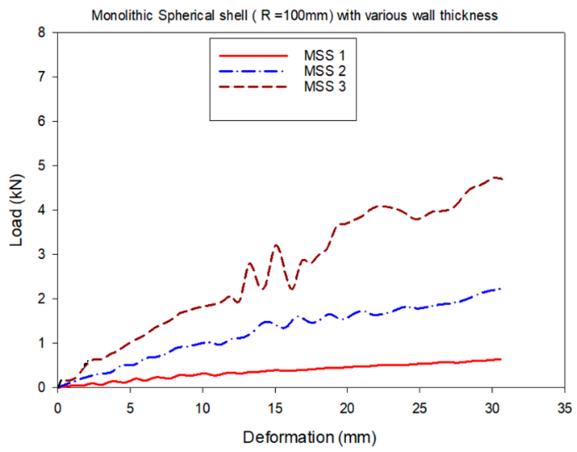
Equivalent P-δ curves are also revealed in these record for assessment is shown in Figure 6.
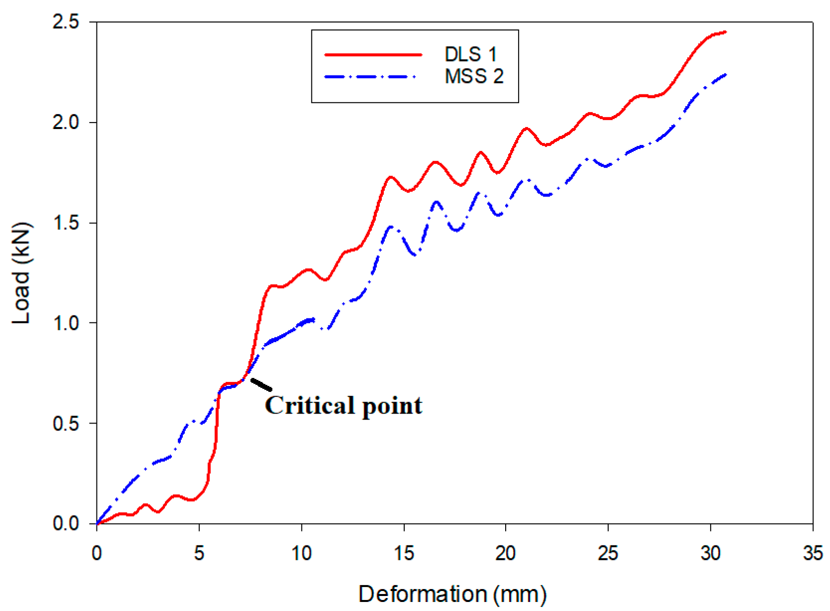
Figure 7 illustrates the typical deformed results of monolithic shell of thickness 1 mm and double-layered shells of 0.5 mm (inner)/0.5 mm (outer) hemi spherical specimens. Figure 8 shows typical results of force–time curves. It is understood that the single layered sphere-shaped shells of thickness 1 mm buckled mainly by inner dimple. In the double-layered shell with the same mass, the inward dimpling was followed by the unsymmetric integral numbers of lobes. In the initial stage, when the sole shell and double layer are exposed to crushing, the load–time curve for both are the same. Then, the dangerous place where the top layer contacted the bottom layer in the double layered shell caused a deviance between the force–time curves jumps to appear. Figure 8 shows a notable difference between monolithic and double layered shell system. Double-layered shells had an extended reaction time and a comparatively stable force plateau while monolithic shells achieved a higher peak force which is undesirable.
Energy absorption (EA) is utilized to assess the capacity of energy absorbing systems. EA capacity of the double-layered shell is higher than that of the monolithic shell of the same mass. Hence, layered configuration is more advantageous than the bulky one.

5. Conclusions

The crushing behavior of the monolithic and double layered hemispherical shells are examined utilizing the UTM tests and numerical calculations. Distinctive buckle modes were detected in the trials. Also, numerical models are utilized and confirmed by experiments. Based on the FE simulation studies, the varied buckle procedures of the binary layer shells are defined, and the ratio of thickness of inner and outer is used to recognize the buckle mechanism after the crucial point when the top shell contacts with the bottom shell. Finally, parametric examination is performed for better understanding of the layering effect. The outcomes show that the thickness and radius of the shells are the influencing factor for the crushing performance and the energy absorption capability of the double-layered shells.

Author Contributions

N.M.M.I.: Conceptualization, methodology, validation, formal analysis, supervision, project administration, writing, original draft preparation, writing, review and editing, and visualization. K.S.R.: investigation, resources, and data curation. All authors have read and agreed to the published version of the manuscript.

Funding

This research received no external funding.

Institutional Review Board Statement

Not applicable.

Informed Consent Statement

Not applicable.

Data Availability Statement

The data will be provided on request.

Acknowledgments

The authors thank the SSN Management for successfully completed the research.

Conflicts of Interest

The authors declare no conflicts of interest.

References

  1. Gupta, N.K.; Sheriff, N.M.; Velmurugan, R. Experimental and numerical investigations into collapse behaviour of thin spherical shells under drop hammer impact. Int. J. Solids Struct. 2007, 44, 3136–3155. [Google Scholar] [CrossRef]
  2. Gupta, N.K.; Sheriff, N.M.; Velmurugan, R. Experimental and theoretical studies on buckling of thin spherical shells under axial loads. Int. J. Mech. Sci. 2008, 50, 422–432. [Google Scholar] [CrossRef]
  3. Karagiozova, D.; Zhang, X.; Yu, T.X. Static and dynamic snap-through behaviour of an elastic spherical shell. Acta Mech. Sin. 2012, 28, 695–710. [Google Scholar] [CrossRef]
  4. Zhang, X.; Fu, R.; Yu, T.X. Experimental study on static/dynamic local buckling of ping pong balls compressed onto a rigid plate. In Proceedings of the Fourth International Conference on Experimental Mechanics, Singapore, 18–20 November 2009; Quan, C., Ed.; SPIE Press: Bellingham, WA, USA, 2010. [Google Scholar]
  5. Dong, X.; Gao, Z.; Yu, T.X. Dynamic crushing of thin-walled spheres: An experimental study. Int. J. Impact Eng. 2008, 35, 717–726. [Google Scholar] [CrossRef]
  6. Morris, E.; Olabi, A.G.; Hashmi, M.S.J. Analysis of nested tube type energy absorbers with different indenters and exterior constraints. Thin Walled Struct. 2006, 44, 872–885. [Google Scholar] [CrossRef]
  7. Baroutaji, A.; Gilchrist, M.D.; Olabi, A.G. Quasi-static, impact and energy absorption of internally nested tubes subjected to lateral loading. Thin Walled Struct. 2016, 98, 337–350. [Google Scholar] [CrossRef]
  8. Morris, E.; Olabi, A.G.; Hashmi, M.S.J. Lateral crushing of circular and non-circular tube systems under quasi-static conditions. J. Mater. Process. Technol. 2007, 191, 132–135. [Google Scholar] [CrossRef]
  9. Designation, E. Standard Test Methods for Tension Testing of Metallic Materials; ASTM: West Conshohocken, PA, USA, 2001. [Google Scholar]
  10. Dassault Systèmes, SIMULIA Corp. Abaqus Analysis User’s Manual, Version 6.14, Dassault Systèmes, SIMULIA Corp.: Providence, RI, USA, 2014.
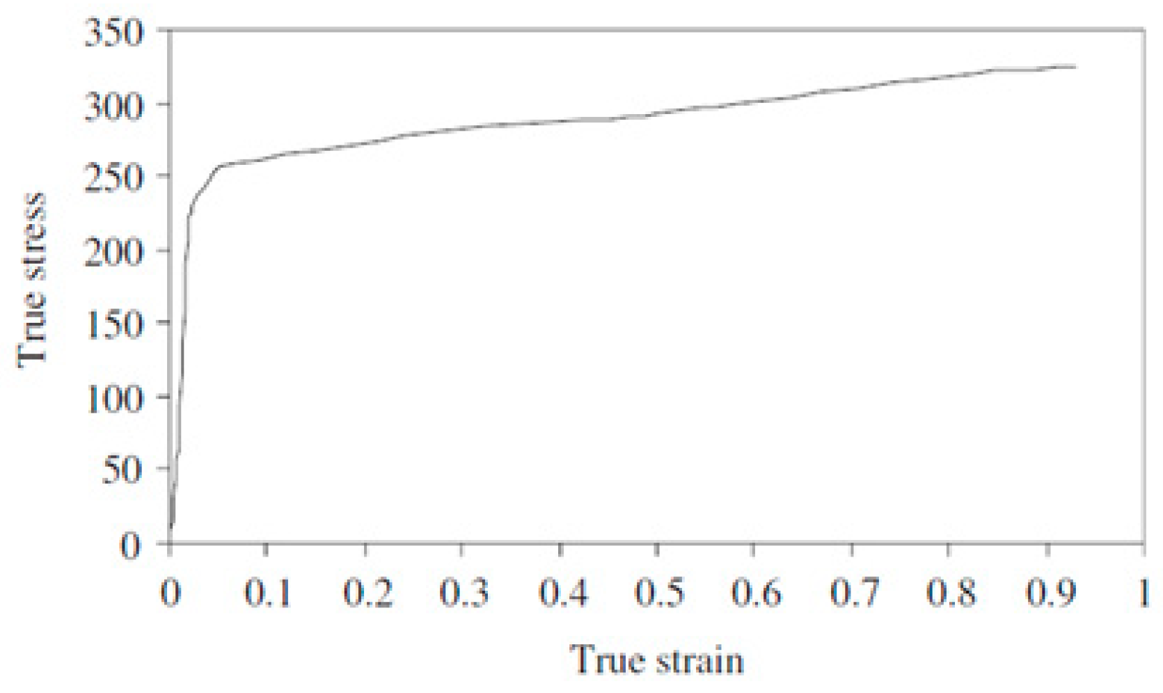
Figure 1. Material properties of aluminum 1100-H12.
Engproc 93 00020 g001
Figure 2. Fabricated monolithic spherical shell structures (MSS).
Engproc 93 00020 g002
Figure 3. FE model of MSS specimen.
Engproc 93 00020 g003
Figure 4. Experimental and numerical collapse modes of MSS1 specimen.
Engproc 93 00020 g004
Figure 5. Deformation history of (a) MSS 1 specimen and (b) MSS 3 specimen.
Engproc 93 00020 g005
Figure 6. Typical P-δ curves for MSS specimen with various thicknesses.
Engproc 93 00020 g006
Figure 7. Comparison of deformed shape of Monolithic and Double-layered Specimen.
Engproc 93 00020 g007
Figure 8. Comparison of Load-Deformation curve of Monolithic and Double-layered specimen.
Engproc 93 00020 g008
Table 1. Geometric details and fabricated monolithic spherical shell structures (MSS).
SpecimenRadiusDepth (mm)Thickness (t)SpecimenRadius (R)
(mm)
Thickness (t)
(mm)
InnerOuterInnerOuter
MSS 11001000.5DLS 199.51000.50.5
MSS 21001001.0DLS 2991000.51.0
MSS 31001001.5DLS 399.51001.00.5
Table 2. Comparison of results on radius of parallel circle (mm) and EA of ‘MSS 1’ specimen.
GeometryRadius of Parallel Circle (mm)EA(kJ)
ExptSoftware% VariationExptSoftware% Variation
MSS 167.170.24.4154.656.22.84
Disclaimer/Publisher’s Note: The statements, opinions and data contained in all publications are solely those of the individual author(s) and contributor(s) and not of MDPI and/or the editor(s). MDPI and/or the editor(s) disclaim responsibility for any injury to people or property resulting from any ideas, methods, instructions or products referred to in the content.