Abstract
The amount of energy consumed worldwide is raising at a startling rate. This has led to a global energy crisis and a hike in fuel prices and has caused environmental jeopardy. Renewable energy resources offer a promising solution to the above situation. Solar energy is examined to be the most liberal source of renewable energy. The efficiency of solar PV cells show nonlinear characteristics and deliver poor performance. Consequently, it is imperative to use the maximum power point tracking (MPPT) technique to extract the optimum amount of energy from photovoltaic (PV) cells. Perturb and Observe (P&O) and Incremental Conductance (INC) are examples of MPPT algorithms. The performance of MPPT schemes below varying climatic ambience should be predominantly considered. The workings of these schemes under various load conditions becomes critical to analyze. This work deals with this issue and compares the conventional P&O MPPT and INC MPPT schemes for various solar irradiation and load conditions and designing solar panels optimized for maximum power generation. The designed MPPT scheme is carried out in the control circuit of a boost converter, evaluating and designing a converter to convert solar panel DC power into grid-compatible AC power. By analyzing different methods for managing and tracking PV power, this method proves to be fast and gives better results under changes in solar insolation.
1. Introduction
Photovoltaic systems are gaining popularity in electrical power generation. The supremacy of usage of photovoltaic systems is increasing exponentially because of its user-friendly nature for small scale loads and distribution networks. The output of solar power is governed by the array voltage. Significant advancements have been made in the technology of PV cells and associated converters, leading to substantial improvements in efficiency.
MPPT shows the distinctive point at which maximum power and efficiency could be derived from, taking into consideration the swapping of climatic conditions. In this work, the methods used are the P&O scheme and INC scheme, and they are discussed. There are still issues, such as some variations brought on by non-uniform solar insolation and temperature [1,2]. Recently, the high cost of fossil fuels has had a significant impact on rural communities, prompting some to rely on generators to meet their electricity needs. Thus, hybrid energy plays a vital role to extend the grid to these villages, and how power supply has reached 84% parts of the country has been discussed [3,4].
This paper focuses on generating the utmost power from the PV modules. A chopper assumes a significant job in the PV systems to achieve high efficiency power transmission. The maximum power point changes over the entire day with different sun powered irradiance and climate conditions. MatLab (version 2018b) software is used to simulate the required PV array and converter. To follow it precisely, a proper estimation of load value must be used. In this work, the dynamic sunlight-based PV mode is modelled, and a step-up converter is utilized for outfitting the immediate utmost energy point. A control algorithm (VSC) for the inverter is introduced to control the current, potential difference, recurrence, and phase angle and reduce the harmonic oscillations and ensure maximum efficiency while transmitting power from PV system to the grid and load [5,6,7].
2. System Representation
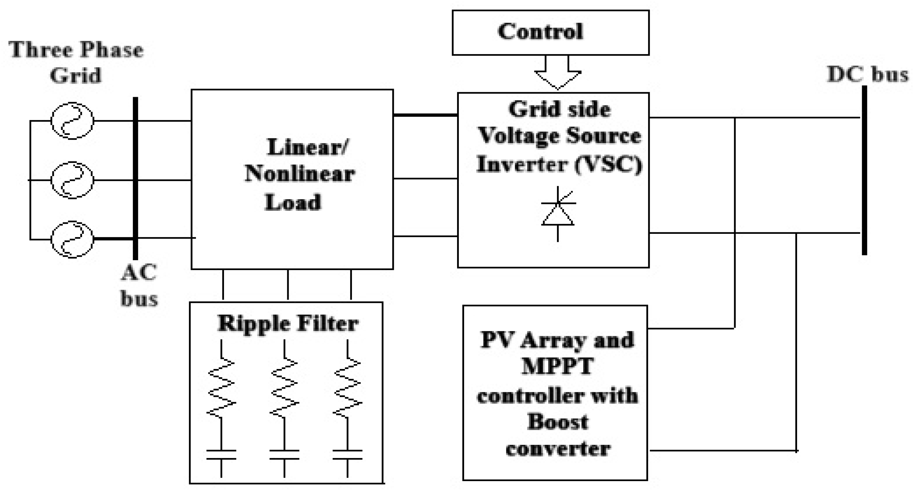
The proposed network is schematically represented in Figure 1.
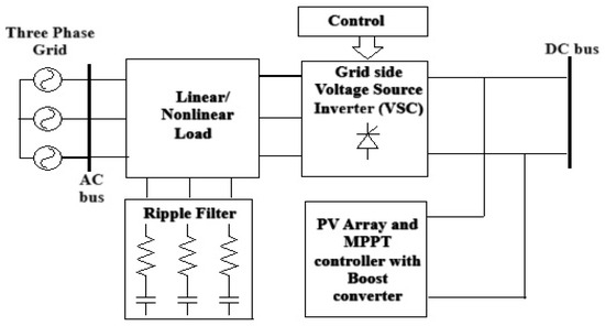
Figure 1.
Structure of the proposed system.
The proposed network components comprise a 2.4 kW PV array, a boost converter, MPPT methods, a 3-phase neutral clamped inverter, a GVSC voltage source control algorithm, a ripple filter, a 10 kV AR load, and a 25 kV distribution feeder utility grid. An elaborated structure of the proposed work and simulation model are presented in the following sections.
2.1. Modelling and Simulation of PV Array Using MatLab
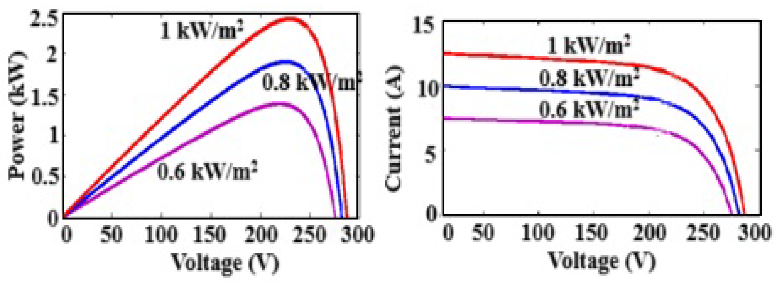
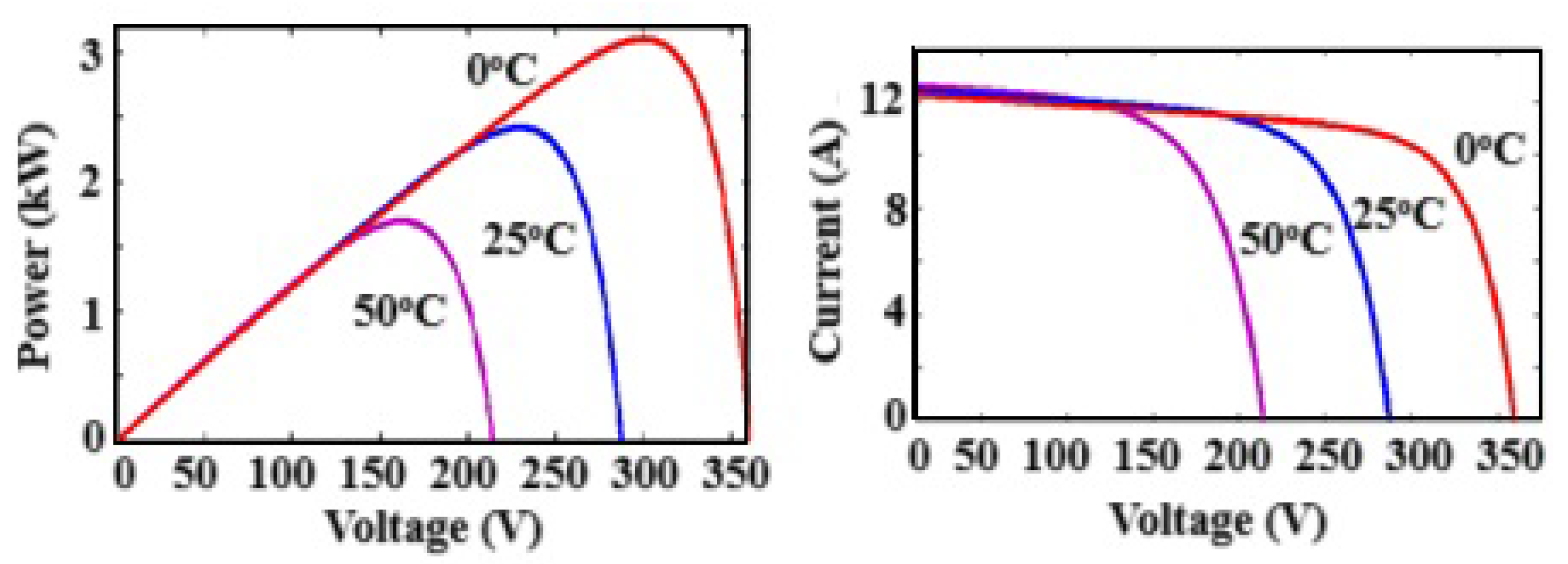
The equivalent circuit with basic equations of PV array and its characteristics is described in [8,9]. Here, a PV array of (14 × 5) is used. The insolation (G) of 1000 W/m2 with temperature (T) of 25 °C is specified for a single panel and their parameters are as follows: open circuit voltage (Voc) = 17.5 V, maximum power point voltage (Vmax) = 16.5 V, maximum power point current (Imax) = 2.1 A, and short circuit current (Isc) = 2.5 A. Figure 2 and Figure 3 show the PV panel characteristics under various temperatures and irradiances, which were acquired using the MatLab software [10].
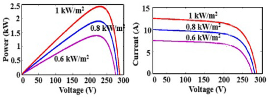
Figure 2.
PV array characteristics at same temperature and different irradiances.

Figure 3.
PV array characteristics at same irradiance and different temperatures.
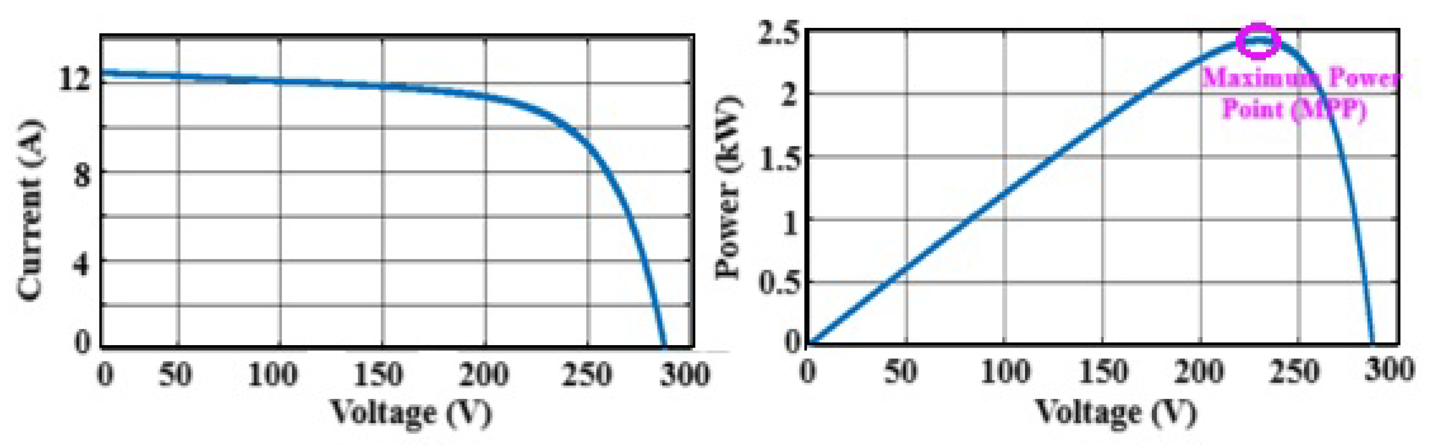
The simulated characteristics of the PV array at STC are shown in Figure 4, which indicates the knee points [4].
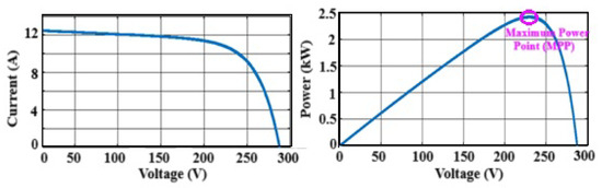
Figure 4.
Characteristics of PV array obtained using MatLab.
2.2. Analysis and Comparison of MPPT Methods
The P&O and INC MPPT methods are analyzed and its comparison result is obtained using MatLab and is depicted in Table 1.

Table 1.
P&O and INC methods comparison.
It is inferred from the above tabulation that the INC method is better in terms of accuracy, reliability, and efficiency.
2.3. Design and Simulation of Step-Up Converter
The step-up converter is designed based on the following parameters, with their respective values provided in Table 2.
Table 2.
Design parameters of boost converter.
The parameters used for the boost converter are calculated below.
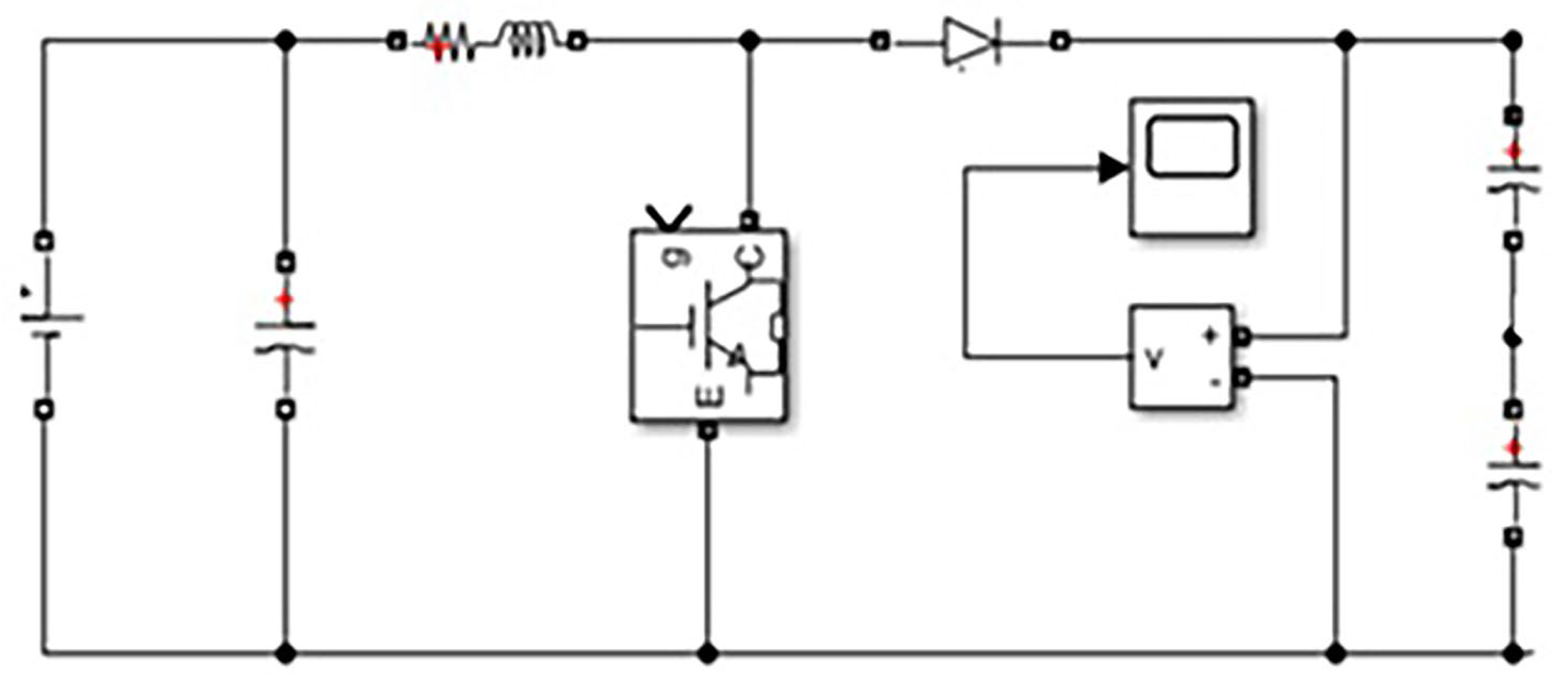
The Simulink diagram of the step-up converter is presented in Figure 5.

Figure 5.
Step−up converter simulation using MatLab.
2.4. Simulation of Neutral Point Clamped Inverter
It is important for current and voltage harmonics to be considered while designing a converter to enhance the energy rate of the system. Converters normally produce current and voltage waveforms which are distorted in nature. NPC inverters are designed for this purpose. They help to maintain a balance in peak voltage and to reduce the distortions at the neutral point. The simulation is accomplished using a MatLab simulation script [6]. The MatLab simulation of the NPC Inverter is shown in Figure 6.
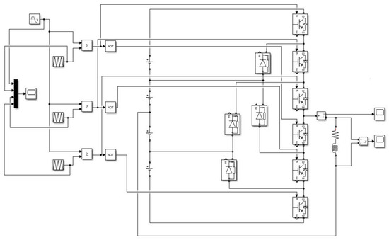
Figure 6.
Neutral point clamped inverter using MatLab.
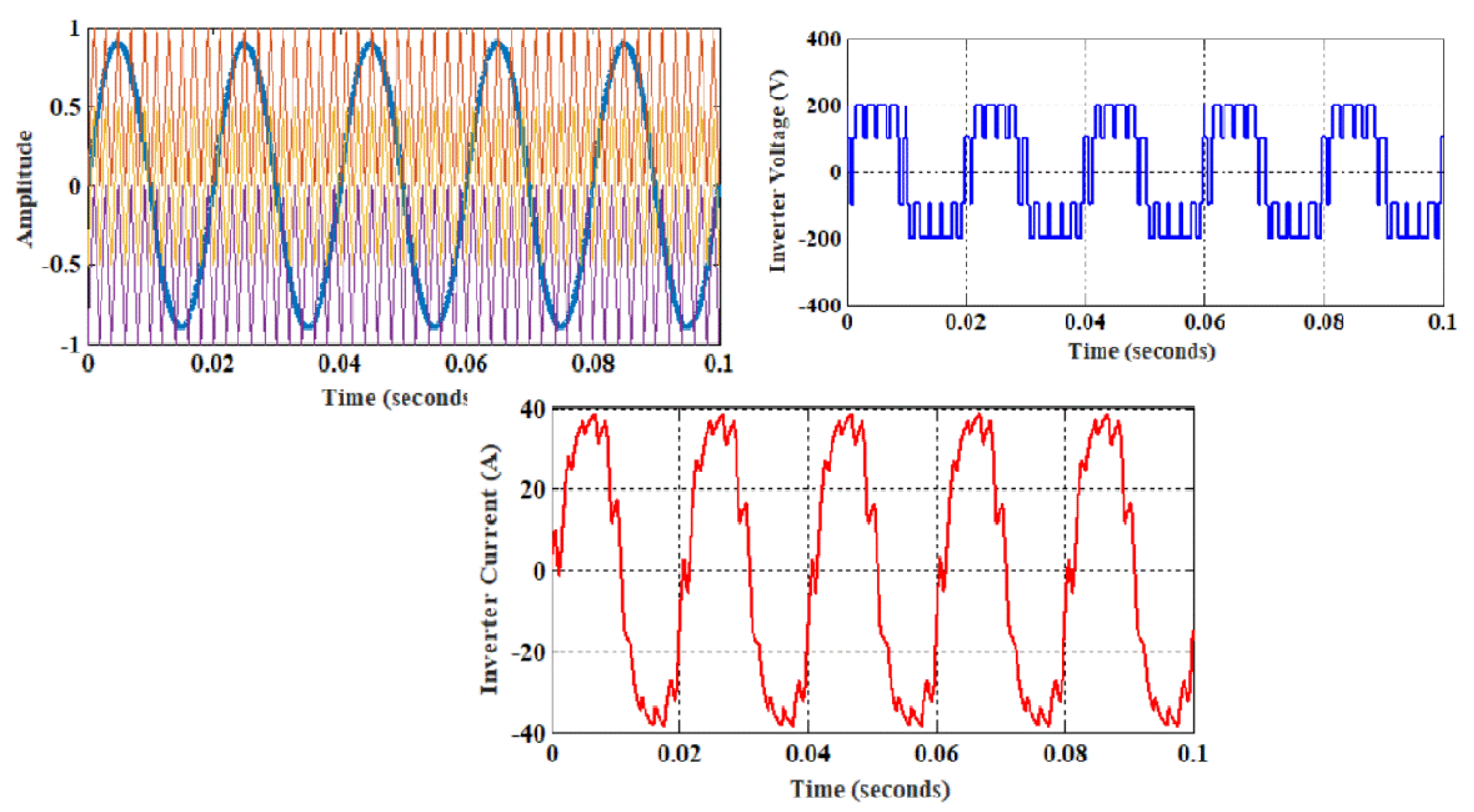
The designed simulation is for a 4-level inverter. The DC input voltage given is 400 V, which is the voltage maintained at the DC link. A total of six IGBT switches, two diodes and four DC sources, each 100 V dc, are used as the components. For simulating a 4-level AC output, the switching state of six switches play a major role. Sine wave and repeating sequence blocks are compared using a relational operator and given as input gate pulses. Three repeating sequence blocks with the same time values but different output values are used. RL load is connected across the midpoints. The generated pulse, which is used to adjust the switching states, along with the four-level voltage output and current output, are depicted in Figure 7.
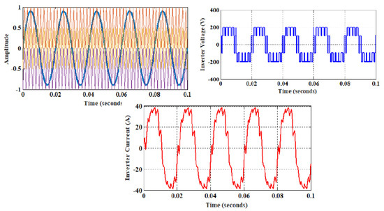
Figure 7.
Pulse generation, NPC inverter voltage, and current output waveforms using MatLab.
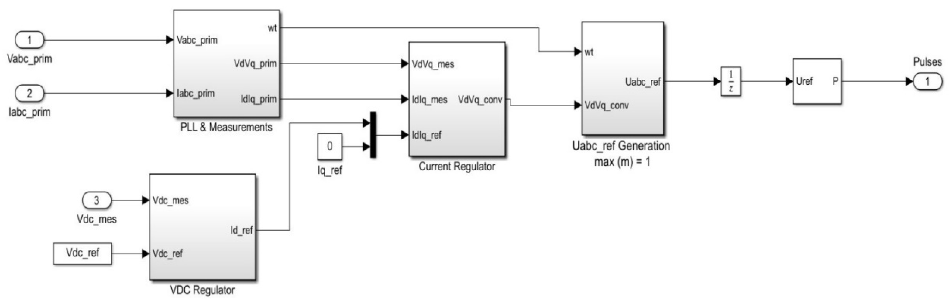
2.5. Design of Voltage Source Control Algorithm
For a converter on the grid side, a control method of the standpoint set along the voltage of the inverter is endorsed, so that the real power and imaginary power transmitted from PV to the grid and load can be independently modified and taken control of. In a control technique, the inner side is occupied by current control loop and the outer side is occupied by a DC link voltage regulator [7]. If the reference value of the imaginary power is kept at 0, then the inverter operates in unity power factor mode to produce maximum power output. The MatLab Simulink design of the VSC main controller is shown in Figure 8.
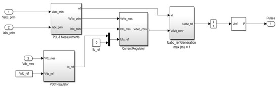
Figure 8.
VSC main controller simulation using MatLab.
3. Simulation Results and Interface
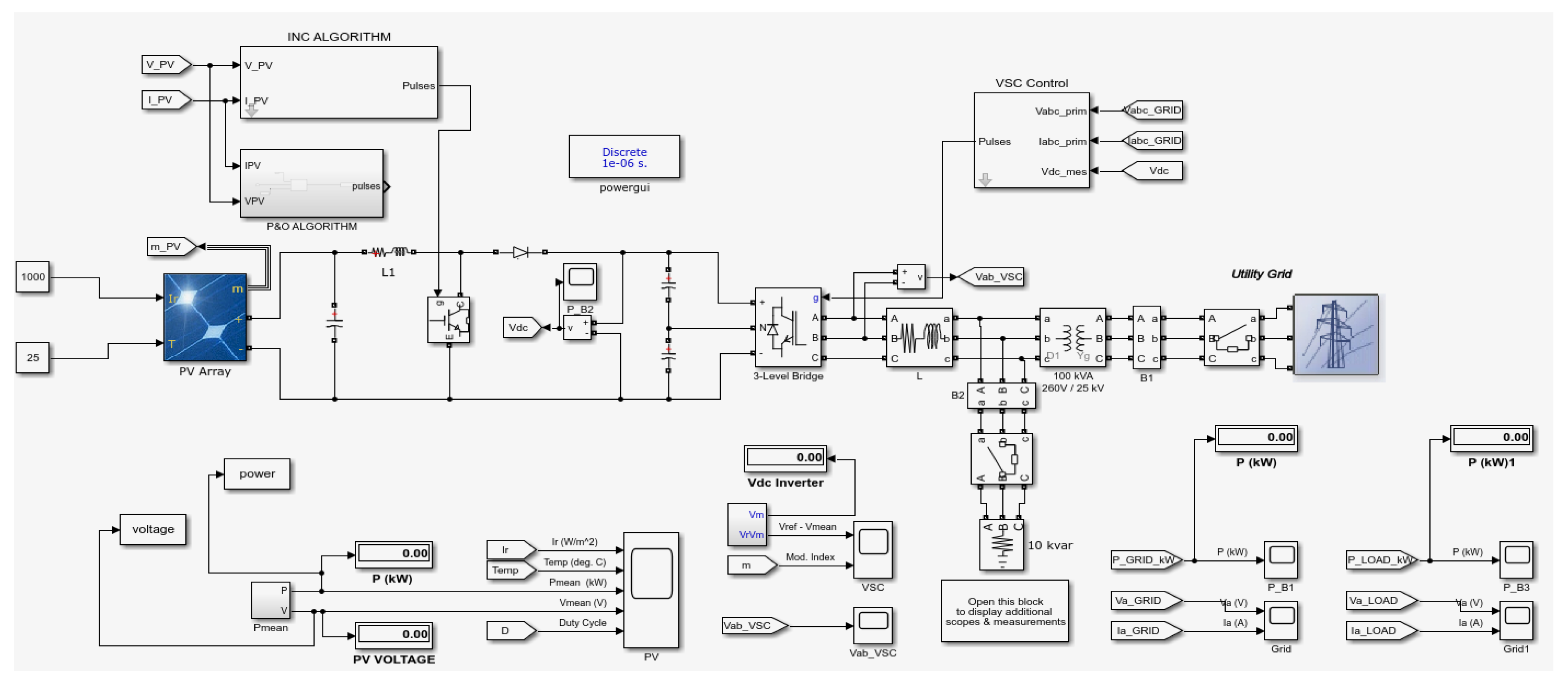
In this work, the PV array is implemented to supply power to both the grid and load during different time intervals. The PV array supplies power to the grid during the switching time interval [0 1]. A breaker is used for this purpose. It enables the opening and closing of the circuit during the respective time interval. During time interval [1 2], the switches supply from the grid to the domestic load. In times of excess load, the grid starts supplying power to the load. A solar PV array of rating 2.4 kW is tracked by a MPPT Control Algorithm, ensuring maximum power at all times. The PV array voltage is given to the boost converter, which increases the voltage to a higher level and ensures a stable voltage across the DC link. A Voltage Source Converter (VSC) control technique is then employed to regulate the voltage on the link and control the grid’s frequency, phase angle, voltage, and current. The inverter then converts the DC voltage to ac. A choke is used to mitigate current harmonics and distortions. A step-up transformer increases the voltage from hundreds of volts to many kVs. Breakers are installed to enable the switching sequence between the grid and load. The PV array supplies the power either to the grid or the load at one time. In the case of excess load (in this case, when load is greater than 10 kV AR), the grid starts supplying power from the grid to the load. This proposed system allows for the introduction of renewables into the consolidated grid and demonstrates the economic attainability of rooftop PV systems as the exclusive means of renewable production [8,9,10]. Figure 9 depicts the Simulink model for AC microgrid configuration.

Figure 9.
Integrated AC microgrid system using MatLab.
Simulation waveforms of the integrated AC microgrid system are shown in Figure 10. The encircled portion represents the zoomed output waveforms when switching takes place.
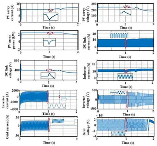
Figure 10.
Output waveform of integrated AC microgrid (zoomed portion is encircled in figure).
4. Hardware Implementation
In this section, the entire hardware circuit model of a simple converter–inverter is designed with a regulated AC supply and a simple lamp as the load. A 50 V supply from the regulated AC supply source is given to the PIC microcontroller through a 230/12 V transformer. The PIC Microcontroller (16F877A) along with the driver circuit (20 kHz) rectifies the given AC supply to its equivalent dc. The output from the microcontroller is given to the designed boost converter, which boosts the 50 V to 110 V dc. This output is fed to a 3-phase inverter with six switches which converts the DC to AC supply. The AC output from the inverter is fed into a step-up transformer to increase its voltage to a level suitable for the load. The implementation of hardware is depicted in Figure 11.
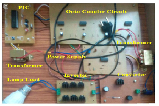
Figure 11.
Hardware setup of a converter.
The results obtained from this prototype are presented in this paper for an input voltage range of 50 V to 110 V. The boost converter steps up the input voltage, and the DC is then converted into ac, which is supplied to the load. The analyzed voltage and current are represented in Figure 12.
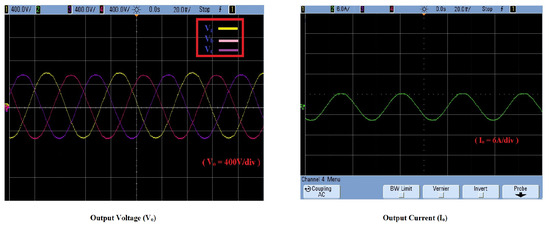
Figure 12.
Output waveforms of voltage and current.
5. Conclusions
The outcome of the simulation results are analyzed. A PV array, when implemented with a maximum power point tracking system, shows better results compared to a traditional PV system. Since the power is transmitted from the input to output, the efficiency of the system increases. Irrespective of the temperature and irradiance at any point of time, maximum power is ensured at all conditions with the help of this system. Further, the results of two important MPPT schemes were compared, and the incremental conductance (INC) method proves to be better than perturb and observe (P&O) method in terms of efficiency, accuracy, and reliability. Implementing the boost converter will increment the solar panel voltage to the sustainable voltage required by electronic equipment. In compliance with grid codes, the VSC control algorithm in the grid-side converter manages the DC link voltage and ensures the supply of imaginary power to the grid. The frequency, phase angle, current, and voltage are all maintained by synchronizing the inverter with the utility grid by using the voltage source converter algorithm. A hybrid model developed for the grid and local load helps to switch between the two parameters, depending on the generated power and the load demand. Thus, a hybrid system which transmits maximum power to the grid and load without harmonics or disturbances is developed from renewable energy resource.
Author Contributions
Conceptualization, R.R.; methodology, R.A.B., R.L. and P.M.; software R.A.B., R.L. and P.M.; validation, R.A.B., R.L. and P.M.; visualization, R.A.B., R.L. and P.M.; investigation, S.S.; resources, R.R.; writing—original draft preparation, S.S.; writing—review and editing, S.S.; supervision, R.R. All authors have read and agreed to the published version of the manuscript.
Funding
This research received no external funding.
Institutional Review Board Statement
Not applicable.
Informed Consent Statement
Not applicable.
Data Availability Statement
Data sharing is not applicable.
Acknowledgments
The authors would like to acknowledge the management of SSN college of Engineering for the support.
Conflicts of Interest
The authors declare no conflicts of interest.
References
- Alazrag, A.; Sbita, L.; Fekik, A. Control of grid-connected photovoltaic system. In Power Electronics Converters and Their Control for Renewable Energy Applications; Academic Press; Mouloud Mammeri University: Tizi Ouzou, Algeria, 2023; pp. 1–325. [Google Scholar]
- Radisavljevic-Gajic, V.; Karagiannis, D.; Gajic, Z. Linear, Nonlinear, and Distributed-Parameter Observers Used for (Renewable) Energy Processes and Systems—An Overview. Energies 2024, 17, 2700. [Google Scholar] [CrossRef]
- Khan, H.S.; Memon, A.Y. Robust Output Feedback Control of the Voltage Source Inverter in an AC Microgrid. Energies 2022, 15, 5586. [Google Scholar] [CrossRef]
- Wang, R.; Wu, X.; Wang, X. Three-Phase Hybrid Converter With Simultaneous DC and AC Outputs. IEEE Access 2023, 11, 24382–24393. [Google Scholar] [CrossRef]
- Singh, S.; Aggarwal, V.; Kumar, M. Power Flow Management of Solar PV fed Switched Boost Inverter. In Proceedings of the IEEE 3rd International Conference on Sustainable Energy and Future Electric Transportation (SEFET), Bhubaneswar, India, 9–12 August 2023; pp. 1–6. [Google Scholar]
- Chandu, H.S. Robust Control of Electrical Machines in Renewable Energy Systems: Challenges and Solutions. Int. J. Innov. Sci. Res. Technol. (IJISRT) 2024, 9, 594–602. [Google Scholar] [CrossRef]
- Magableh, M.A.; Radwan, A.; Mohamed, Y.A. Interaction Dynamics Analysis and Active Stabilization of a Weak Grid-Tied Hybrid PV-Wind Power Generator. IEEE Trans. Smart Grid 2024, 15, 3808–3823. [Google Scholar] [CrossRef]
- Sayyad, J.K.; Nasikkar, P.S. Solar photovoltaic module performance characterisation using single diode modeling. E3S Web Conf. 2020, 170, 01023. [Google Scholar] [CrossRef]
- Pandiarajan, N.; Ramaprabha, R.; Muthu, R. Application of Circuit Model for Photovoltaic Energy Conversion System. Int. J. Photo Energy 2012, 2012, 410401. [Google Scholar] [CrossRef]
- Available online: www.mathworks.com (accessed on 7 October 2023).


Disclaimer/Publisher’s Note: The statements, opinions and data contained in all publications are solely those of the individual author(s) and contributor(s) and not of MDPI and/or the editor(s). MDPI and/or the editor(s) disclaim responsibility for any injury to people or property resulting from any ideas, methods, instructions or products referred to in the content. |
© 2025 by the authors. Licensee MDPI, Basel, Switzerland. This article is an open access article distributed under the terms and conditions of the Creative Commons Attribution (CC BY) license (https://creativecommons.org/licenses/by/4.0/).