Abstract
The aviation industry, responsible for a significant portion of global CO2 emissions, faces the need to transition to more sustainable aircraft. Electric aircraft driven by battery-powered propulsion and further structural weight reductions have emerged as potential solutions. This research presents structural topology optimization methods developed at the Netherlands Aerospace Centre using (1) a hybrid approach with different scales for aircraft design, from component to full-scale aircraft. Furthermore, (2) multi-material designs are being explored in combination with additive manufacturing technology. Method 1: At the full aircraft level, the study employed a preliminary design methodology that combines shell and solid elements in a 3D model utilizing Abaqus software 2023. A topology optimization was carried out with strain energy and weight as the design responses, subject to specified volume and symmetry constraints. Different aircraft configurations were investigated, including blended wing designs, with each impacting the load paths and structural performance. A start was made in translating the optimized design to actual aerospace features such as frames and Door-Surround Structures (DSS). Method 2: The ability to manufacture multi-material metal parts via additive manufacturing presents opportunities for the design of aircraft components and shows weight-saving potential. The multi-material topology optimization method is explored for a relevant aerospace wing component. The results revealed widespread possibilities for general topology optimization methods to be applied in aircraft structural design at different scales. Load paths can be identified and their integration into multi-disciplinary design optimization (MDO) is promising. Novel structural designs for blended wing aircraft can be obtained for multiple load-cases. This research addresses questions concerning the aircraft-level and component-level feasibility of optimized designs, optimization features, inertia relief, and mesh size influence. The findings show the potential to optimize battery-powered aircraft through innovative structural design, contributing to a potentially lower weight and further reductions in environmental impact. This study serves as a first step towards lightweight future electric aircraft design and underscores the importance of integrating innovative solutions to reduce the climate impact of the aviation industry.
1. Introduction
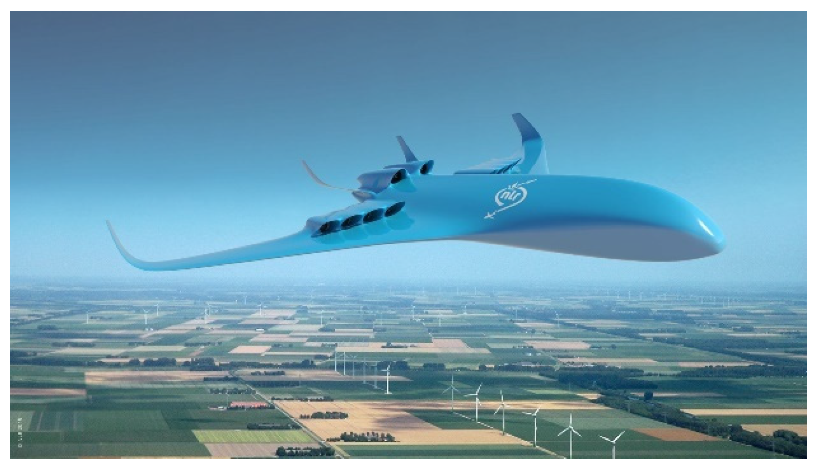
The aviation industry faces the need to address its carbon footprint. A way to achieve this transition is the reduction in aircrafts’ structural weight and the development of non-conventional designs [1,2]; see Figure 1. Also, the adoption of electric propulsion systems promises to significantly reduce greenhouse gas emissions and mitigate the environmental impact of aviation.
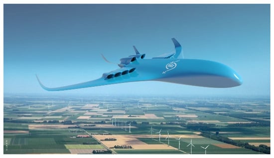
Figure 1.
NLR future aircraft vision [2].
However, this transition is not free of challenges. The introduction of batteries, while promising greener flight operations, necessitates a fundamental re-evaluation of structural design principles. The redistribution of weight, alteration in load paths, and optimization of structural components are important considerations in the search for both efficiency and safety.
The present research undertakes a comprehensive investigation into two methods of structural topology optimization for future aircraft. Central to this research is the objective of achieving an optimal balance between weight reduction and structural integrity.
- Method 1 focuses on the full aircraft level, aiming to achieve a preliminary design methodology that combines shell and solid elements in a 3D model, utilizing Abaqus software;
- Method 2 focuses on manufacturing multi-material metal parts that show weight-saving potential through the use of Additive Manufacturing (AM). The multi-material topology optimization method is explored for a relevant aerospace wing component. This study responds to the demand for innovative design methodologies that can be used for future aircraft.
2. Approach
In this section, the two used methodologies are introduced and explained. These are the (1) method of full aircraft-level optimization and (2) the method of multi-material part optimization.
2.1. Method 1: Full Aircraft Level
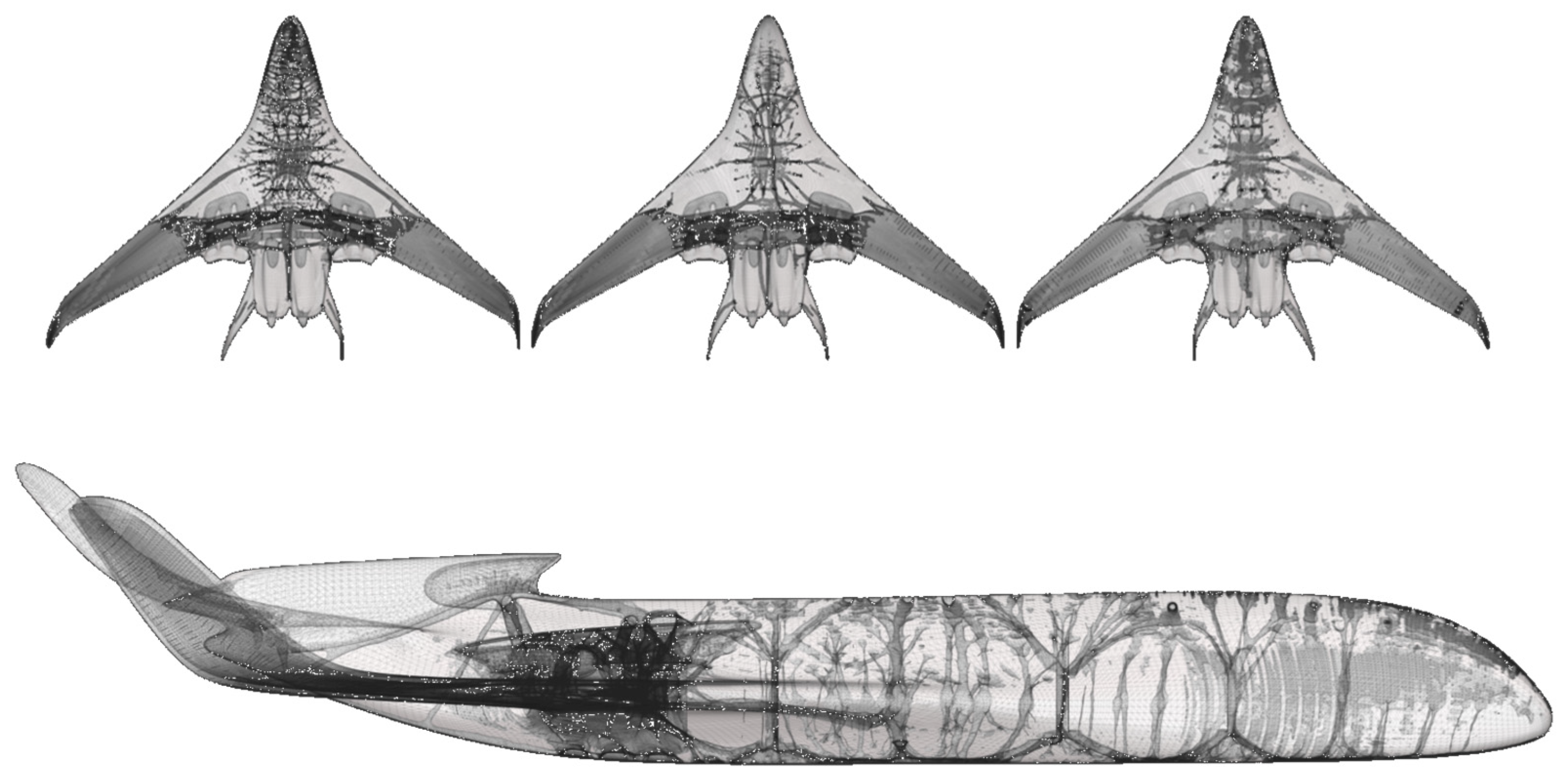
The use of computational morphogenesis for structural design has been investigated by researchers, who highlighted its potential for optimizing complex geometries in aircraft [3,4]. In the research, topology optimization techniques were applied to aircraft fuselages, showcasing the efficacy of lightweight designs in the context of electric propulsion [5,6,7]. Topology optimization has gained traction as a powerful tool in aircraft design, enabling engineers to create lightweight and robust structures. The potential of laser metal deposition to optimize complex aluminum structures, thereby reducing energy input for AM in aircraft components, is shown [8]. This study aligns with the growing interest in leveraging topology optimization to address structural challenges in the context of electric aircraft. While the aforementioned research generally focuses on solid or voxel structure optimization, the thin skins of aircraft are often not included or very coarsely modelled. In this research, the thin aerodynamic skin of aircraft, which is essential for shear loading, is included in the design as a separate part, where the internal solid structure reinforces the aircraft structure; see Figure 2.
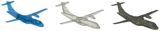
Figure 2.
Full aircraft models: (left) the solid geometry (design space); (middle) the outer surface shell representing a skin of 1 mm thickness; (right) a combined hybrid mesh of shell and solid elements.
The principal aim of this research is to explore the structural design of conventional and novel aircraft concepts such as blended wings. The ambition is to include this structural design in multi-disciplinary design optimization (MDO). The objectives encompass the following key aspects:
- Load analysis and characterization: Quantifying and analyzing the diverse array of loads that act on the aircraft, including gravity, internal pressure, wing loading, control surfaces, system weight, and multiple operational conditions.
- Hybrid modelling approach: Employing advanced modelling techniques that blend shell and solid elements to accurately simulate the structural behavior of the fuselage and wing.
- Topology optimization: Utilizing strain energy and structural volume as design responses to achieve an optimal structural configuration that balances weight reduction with structural robustness.
- Aircraft shape and battery placement configurations: Investigating various novel configurations of shape and battery placement within the fuselage and wing, evaluating their influence on load paths and structural performance.
For the topology optimization, the objective is to obtain the minimum strain energy with an outer-skin aerodynamic surface of 1.5 mm. The constraints are volume and symmetry. The element size ranges from 50 mm to 200 mm and the material has isotropic aluminum properties.
2.2. Method 2: Multi-Material Design
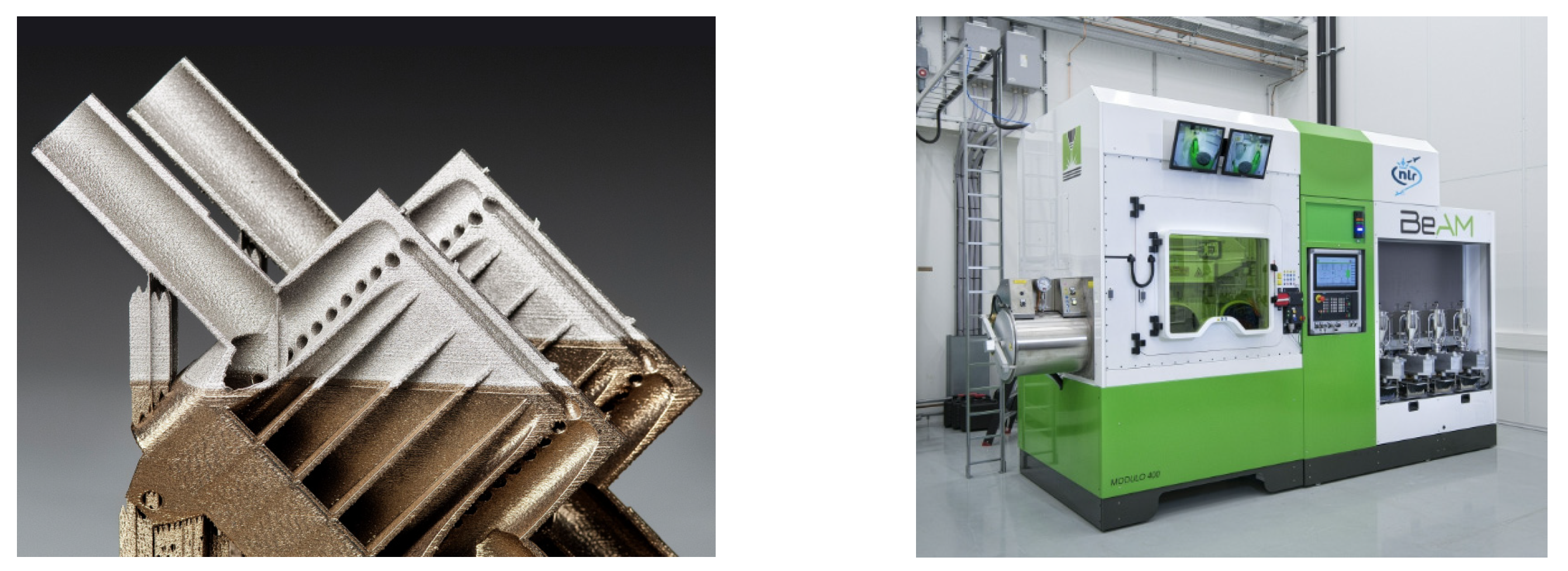
At the NLR Metal Additive Manufacturing Technology Centre (MAMTeC), multi-material additive manufacturing is carried out using the BEAM Modulo 400 machine, a directed energy deposition (DED) machine. DED opens new opportunities for designing, optimizing, and manufacturing aircraft components; see Figure 3.
Multi-material topology optimization (MMO) has been researched quite extensively as an extension of single-material optimization. The challenge in the topology optimization of multi-materials is determining an appropriate mathematical formulation of the interpolation function and the optimization model, which would enable each material in the design domain to be completely covered without overlapping. Another challenge is determining whether the use of multi-material parts would result in a considerable weight reduction compared to a single-material design. A common approach is to use a mapping-based interpolation function where each material can obtain a zero-density or full-density result for the optimized structures [9]. Interesting research has applied a multi-material, parametric, level set-based topology optimization to simultaneously distribute structural and viscoelastic material to optimize damping characteristics [10]. In commercial finite element software, Altair MMO [11] has been presented as an option; however, it has not been tested, compared, or mentioned in previous publications.

Figure 3.
(left) A multi-material additive manufactured part. (right) The DED machine at NLR [12].
Figure 3.
(left) A multi-material additive manufactured part. (right) The DED machine at NLR [12].
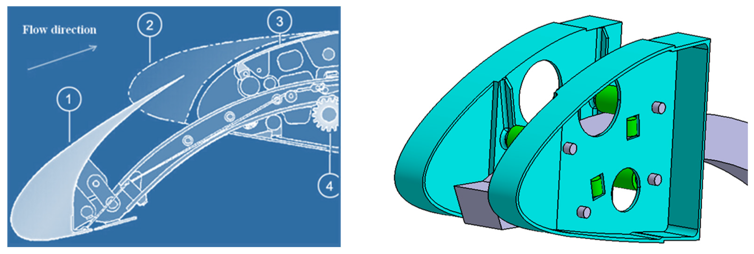
For this research, a 2D multi-material topology optimization approach was developed and a simplified multi-section material topology optimization was carried out using the finite element software Abaqus. In the latter, the areas where the material was used were pre-defined. For demonstration purposes, an aircraft wing leading edge rib section, as shown in Figure 4, was optimized for processing using DED technology.

Figure 4.
(left) A wing cross-section with a leading edge slat track system, with the ribs indicated by (#3). The original slat position is indicated by (#2) and the extended slat position by (#1). The motor gear for extending the slat system is indicated with (#4). (right) The CAD model of the same simplified system. The turquoise ribs were subject to multi-material topology optimization.
For the topology optimization, the Ti6Al4V alloy and Ti6Al4V reinforced with 5% TiC particles were used. The resulting strength following the addition of TiC particles was around 10% higher. The objective of the optimization is to increase the stiffness and strength of highly loaded areas in the design and to create a more efficient component. The ribs were supported at the spar side with bolts and a total load of 60 kN was applied to the four green rollers; see Figure 4. The topology optimization was performed using stiffness and stress constraints with weight minimization as the objective.
3. Results
3.1. Results 1: Full Aircraft Level
The full aircraft-level optimization was performed on different aircraft shapes; see Figure 5. The ATR-42 conventional aircraft has electric propulsion and two blended wing designs.
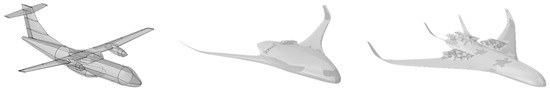
Figure 5.
(left) The aerodynamic shape of the ATR-42 conventional aircraft. (middle) A shape similar to the Airbus Zero-e aircraft and (right) a study of a blended-wing aircraft.
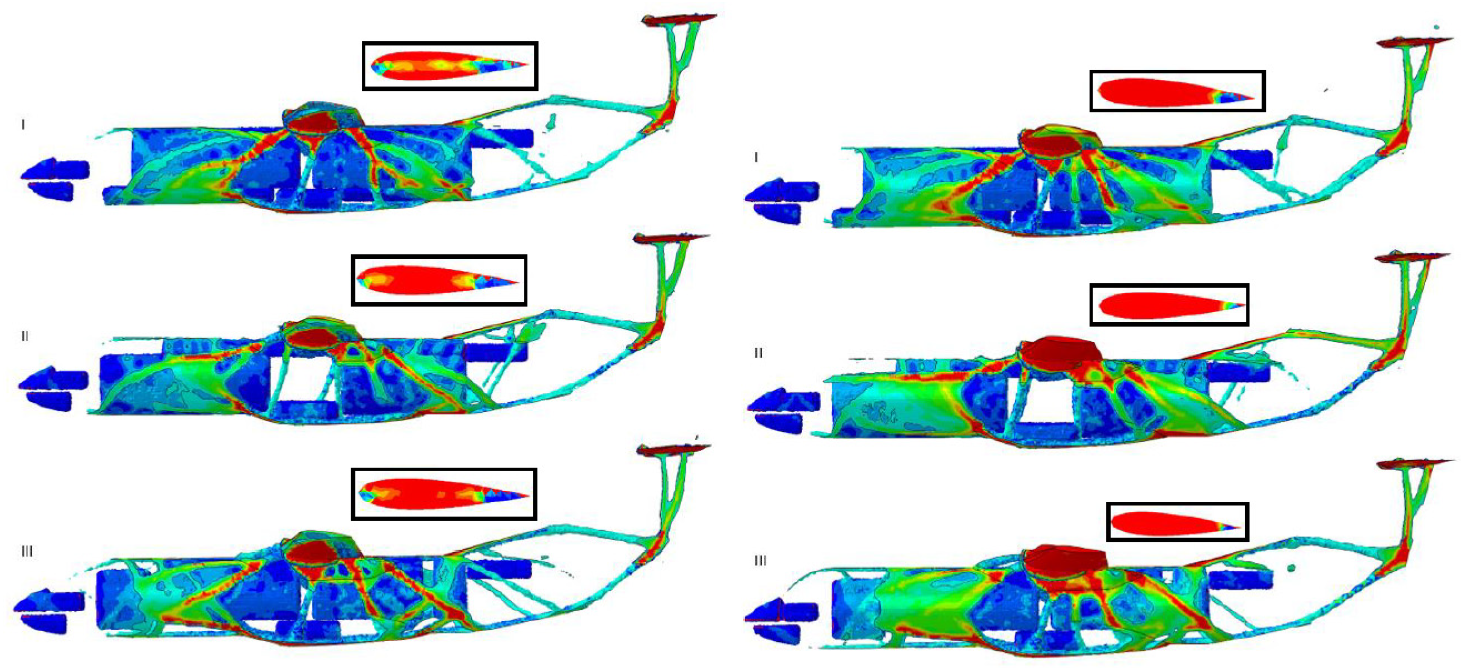
The ATR-42 aircraft equipped with electric propulsion was subject to the study design; see Figure 6. The influence of battery placement and number of motors was investigated using the topology optimization approach. From the results, it is clear that when placing the batteries in the fuselage, a large load has to pass through the part that connects these two parts: the wingbox. The wing creates the lift and the batteries introduce large inertia loads. The wingbox’s connection to the fuselage is, therefore, a critical design element for this configuration.
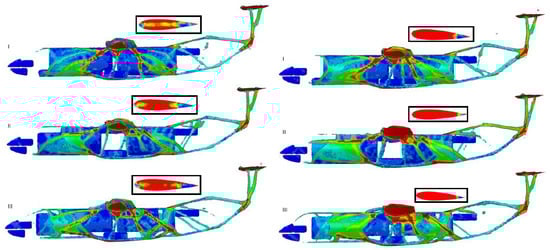
Figure 6.
On the left, the materials used (red represents full material and blue represented low density) in the optimized aircraft configurations with a volume constraint of 25% are shown. Different battery configurations are shown in vertical rows I, II and III, with placement of the battery in the wing and fuselage. On the right, the materials used in all optimized configurations with a volume constraint of 30% and various battery placements are shown. The main load paths are shown in red.
The presented Airbus Zero-e concept is an interesting subject for structural design optimization; see Figure 7. A Zero-e-inspired design was used for the structural topology optimization using the hybrid approach. Here, the main aim was to investigate the load paths and feasibility of the hybrid approach.
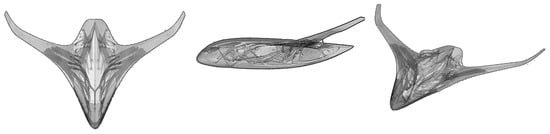
Figure 7.
Results of the Zero-e-inspired design, showing where the load paths can be identified. Most of the load is moved towards the wings.
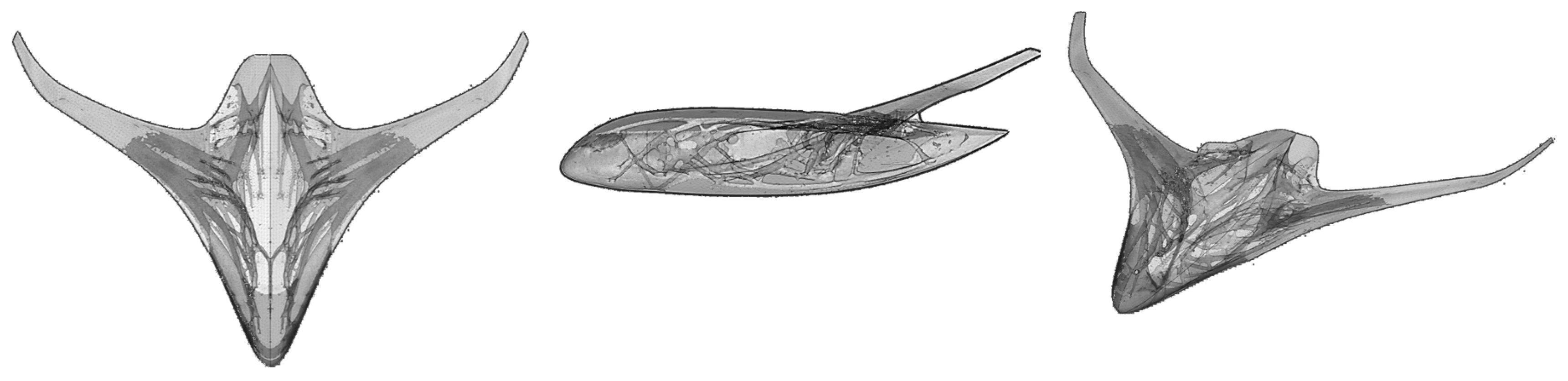
The blended-wing aircraft was studied in detail regarding the load paths and load configurations; see Figure 8. With this design, it becomes apparent that the spar equivalent needs to be significantly large in size and interesting pressure domes form inside the cabin during the optimization. However, it is currently challenging to extract exact metrics on total structural weight. This is a subject for future work.
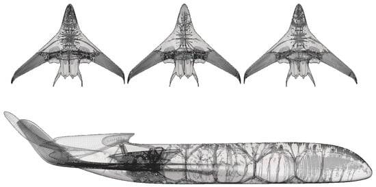
Figure 8.
Results of the blended wing aircraft with different mesh and load configurations. On the top row, the left figure shows the results with an element size of 95 mm, the middle figure shows an element size of 150 mm, and the right figure shows an element size of 150 mm and a higher volume constraint. The load paths can be identified, as well as pressure domes in the fuselage.
3.2. Results 2: Multi-Material Design
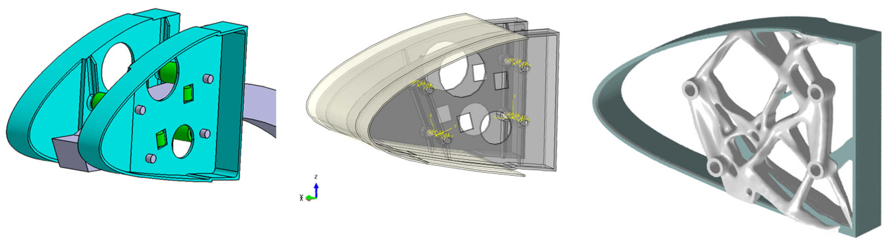
The multi-material leading edge wing rib was optimized using the aforementioned method. The results from the 3D topology optimization using Abaqus and predefined material sections of Ti6Al4V and Ti6Al4V-TiC are presented. The results show that a more efficient structure can be achieved using the presented approach, which can be translated into a lower weight or higher stiffness; see Figure 9. Various options were investigated and the results are presented.
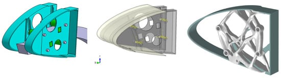
Figure 9.
(left) The CAD model of the conventional slat-track assembly; (middle) the finite element model in Abaqus; (right) the topology-optimized multi-material design.
With the different design settings, a lower weight or higher stiffness can be achieved, as shown in Table 1. In theory, the multi-material setup with the current material selection could offer up to a 10% weight reduction regarding the maximum strength of the respective materials and the full use of Ti6Al4V versus Ti6Al4V-TiC. However, in this case, with the partial use of both materials, the weight reduction was in the order of 1–2%. When the strength/density difference between the two materials is larger, a higher weight reduction can generally be achieved. It should be noted that the reference design does not meet the requirements in terms of stress. Additionally, to manufacture the rib using DED, a support material needs to be added, which would probably increases the weight of the component; see the last column in Table 1. From these configurations, it can be concluded that design 3 shows the highest efficiency.

Table 1.
Results of the multi-material optimization for different configurations, comparing the mass and stiffness variations.
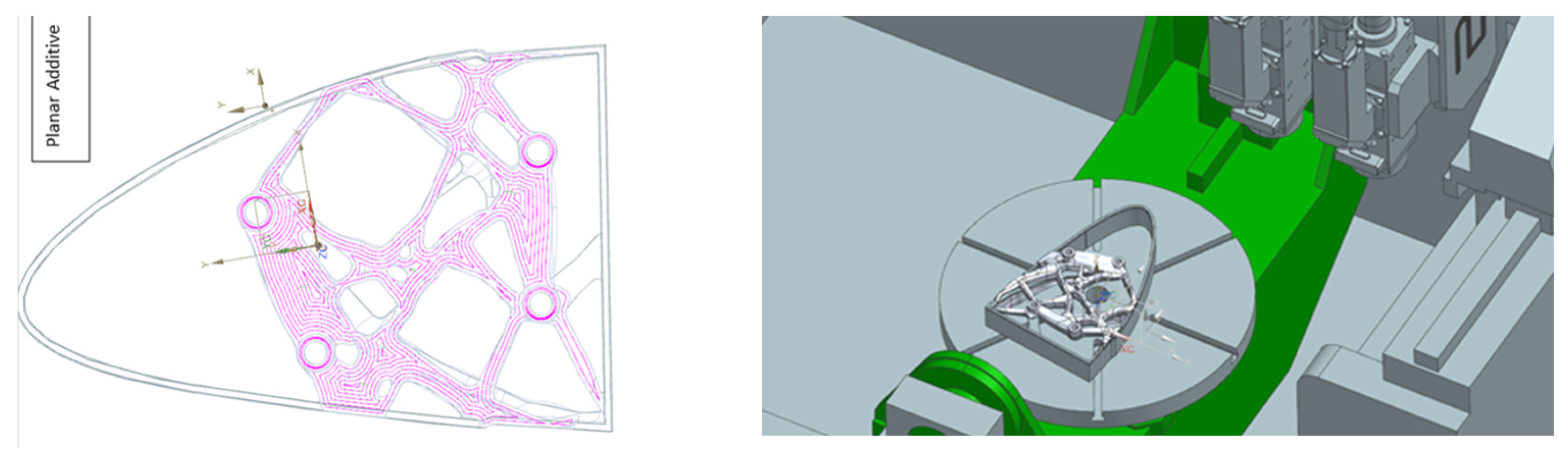
The manufacturing preparations for the DED processing were performed. The next step is to finish the design checks and process the ribs; see Figure 10.

Figure 10.
(left) The DED paths used to deposit the material. The minimum feature size should be noted. (right) The rib position and design in the DED deposition space.
4. Conclusions
The need to reduce the environmental impact of aviation leads to an increased interest in reducing the weight of aircraft. In this context, this study presents a comprehensive exploration of structural topology optimization for aircraft structures using two methods. The goal is to achieve an optimal balance between weight reductions and structural robustness while accommodating the unique challenges posed by the mechanical requirements.
For method 1, through an analysis of diverse loads ranging from gravity and internal pressure to battery loads and cockpit pressure, the study showed the complex interaction of the forces that influence full aircraft designs. The utilization of a hybrid 3D model, blending shell and solid elements, facilitated a detailed representation of the structural behavior under varying conditions. This modelling approach was the starting point for topology optimization, where strain energy and structural volume were used as primary design responses. For method 2, the approach shows how additive manufacturing enables a more efficient design. This is reinforced through the use of multi-material components, which led to an increase, although small, in efficiency, of 1–2%. More work is needed to produce the design via DED and further improve the design process.
In conclusion, this study presents innovative approaches for the structural design of aircraft concepts and multi-material components. By merging advanced modelling techniques with topology optimization, the research provides a valuable framework for engineers and researchers to further enhance electric aircraft design. As the aviation industry continues its search for eco-friendly alternatives, this research contributes to a promising future where innovation and sustainable design are combined.
Author Contributions
Conceptualization, W.v.d.B. and T.K.; methodology, W.v.d.B.; software, W.v.d.B.; validation, W.v.d.B. and T.O.; writing—original draft preparation, W.v.d.B.; writing—review and editing, W.v.d.B., T.K. and M.M.-S.; visualization, W.v.d.B.; project administration, M.M.-S.; funding acquisition, M.M.-S. All authors have read and agreed to the published version of the manuscript.
Funding
This research was funded by; Rijksdienst voor Ondernemend Nederland, Dutch government, grant number; Advanced Alloy Sustainable Structures Enabling Technologies (ASSET) project, TSH-21005.
Institutional Review Board Statement
Not applicable.
Informed Consent Statement
Not applicable.
Data Availability Statement
Data are contained within the article.
Acknowledgments
Advanced Alloy Sustainable Structures Enabling Technologies (ASSET) project, TSH21005, Rijksdienst voor Ondernemend Nederland-Dutch government.
Conflicts of Interest
All the authors were employed by the company Netherlands Aerospace Centre (NLR). The authors declare that the research was conducted in the absence of any commercial or financial relationships that could be construed as a potential conflict of interest.
References
- Airbus. Pioneering Bionic 3D Printing; Airbus: Leiden, The Netherlands, 2022; Available online: https://www.airbus.com/en/newsroom/news/2016-03-pioneering-bionic-3d-printing (accessed on 16 September 2024).
- Eppinga, A. Making It Work: Sustainable Aviation. IO. 30 November 2023. Available online: https://innovationorigins.com/en/making-it-work-sustainable-aviation/ (accessed on 16 September 2024).
- Aage, N.; Andreassen, E.; Lazarov, B.S.; Sigmund, O. Giga-voxel computational morphogenesis for structural design. Nature 2017, 550, 84–86. [Google Scholar] [CrossRef] [PubMed]
- Delissen, A.; Wu, J.; Moller, M.; Aragon, A.M.; Langlaar, M. GPU-Accelerated Matrix-Free Topology Optimization, Poster Flying V; Delft University of Technology: Delft, The Netherlands, 2022. [Google Scholar]
- Kawski, N. Topology Optimization of Fuselage; STELIA Aerospace: Toulouse, France, 2015. [Google Scholar]
- Sogeclair. Structural Study: Electric Regional Aircraft; Sogeclair: Blagnac, France, 2016. [Google Scholar]
- Liu, H.; Hu, Y.; Zhu, B.; Matusik, W.; Eftychios, S. Narrow-band topology optimization on a sparsely populated grid, Electric Aircraft Propulsion Challenges and Innovations. ACM Trans. Graph. (TOG) 2019, 37, 1–14. [Google Scholar]
- Heilemann, M.; Beckman, J.; Emmelam, C. Laser Metal Deposition of Bionic Aluminum Supports: Reduction of the Energy Input for Additive Manufacturing of a Fuselage. Procedia CIRP 2018, 74, 136–139. [Google Scholar] [CrossRef]
- Zheng, R.; Yi, B.; Peng, X.; Yoon, G.-H. An Efficient Code for the Multi-Material Topology Optimization of 2D/3D Continuum Structures Written in Matlab. Appl. Sci. 2024, 14, 657. [Google Scholar] [CrossRef]
- van der Kolk, M.; van der Veen, G.J.; de Vreugd, J.; Langelaar, M. Multi-material topology optimization of viscoelastically damped structures using a parametric level set method. J. Vib. Control 2017, 23, 2430–2443. [Google Scholar] [CrossRef]
- Altair OS-E: 0896 Multi-Material Topology Optimization of Automotive Cradle. (C) Copyright 2021. Available online: https://2021.help.altair.com/2021.2/hwsolvers/os/topics/solvers/os/topology_optimization_multi_material_cradle_example_r.htm (accessed on 17 September 2024).
- De Waal, K. Metal Additive Manufacturing Programme for Certification of Critical Components. Royal Netherlands Aerospace Centre. Available online: https://www.nlr.org/news/metal-additive-manufacturing-programme-for-certification-of-critical-components/ (accessed on 17 September 2024).


Disclaimer/Publisher’s Note: The statements, opinions and data contained in all publications are solely those of the individual author(s) and contributor(s) and not of MDPI and/or the editor(s). MDPI and/or the editor(s) disclaim responsibility for any injury to people or property resulting from any ideas, methods, instructions or products referred to in the content. |
© 2025 by the authors. Licensee MDPI, Basel, Switzerland. This article is an open access article distributed under the terms and conditions of the Creative Commons Attribution (CC BY) license (https://creativecommons.org/licenses/by/4.0/).