Proceeding Paper

Visual Navigation for Lunar Missions Using Sequential Triangulation Technique †

by
Abdurrahim Muratoglu
1,2,3,*,
Halil Ersin Söken
1 and
Ozan Tekinalp
1
1
Department of Aerospace Engineering, Middle East Technical University, 06800 Ankara, Türkiye
2
Institute for Photogrammetry and Geoinformatics, University of Stuttgart, 70174 Stuttgart, Germany
3
Department of Mechanical Engineering, Turkish-German University, 34820 Istanbul, Türkiye
*
Author to whom correspondence should be addressed.
Presented at the 14th EASN International Conference on “Innovation in Aviation & Space towards sustainability today & tomorrow”, Thessaloniki, Greece, 8–11 October 2024.
Eng. Proc. 2025, 90(1), 27; https://doi.org/10.3390/engproc2025090027
Published: 12 March 2025

Abstract

:
A vision-aided autonomous navigation system for translunar missions based on celestial triangulation (Earth and Moon) is proposed. Line-of-Sight (LoS) vectors from the spacecraft to celestial bodies, retrieved using ephemeris data from the designed translunar trajectory, are used to simulate camera observations at unknown locations. The resection problem of triangulation is employed to calculate the relative position of the spacecraft with respect to the observed bodies along the trajectory. The noisy LoS data are processed using the Extended Kalman Filter (EKF). Simulation results demonstrate that, starting from a random initial location, the proposed navigation system can be used for navigating translunar trajectories with the fast and accurate algorithm employed.

1. Introduction

Accurate autonomous navigation capability is crucial to space missions, directly impacting mission success and outcomes. Space missions, particularly deep space missions, are largely impractical for human operators due to biological, logistic, and cost constraints, while autonomous systems can operate without these limitations [1]. Moreover, significant communication delays between Earth and spacecraft, which may reach tens of minutes within the solar system, make real-time ground control impossible during crucial mission phases, further emphasizing the necessity of autonomous navigation for successful deep-space exploration.
Traditional and current navigation systems are largely dependent on the accurate initialization of system states and integration of measurements from Inertial Measurement Units (IMUs). However, this leads to the accumulation of noise and errors, limiting the reliability of estimates over time, which may go into an intolerable range. Furthermore, gravitational perturbations and unknown gravity fields of celestial bodies contribute to this phenomenon [2]. Therefore, IMUs must be aided and integrated with sensors providing absolute position and/or velocity measurements.
Spacecraft navigation and control systems rely on different types of sensors to estimate their position and attitude in space. Although traditional sensors such as star trackers, sun sensors, and magnetometers each serve important roles, cameras have become particularly valuable tools in modern space missions. They offer significant advantages through their versatility, cost-effectiveness, and lightweight design. Moreover, when combined with IMUs, cameras can create highly effective integrated navigation systems [3]. Navigation systems utilizing camera-based images in spacecraft navigation applications are commonly referred to as Optical Navigation (OPNAV) or Vision-aided Inertial Navigation Systems (VINSs) to address the fusion of imagery data with the Inertial Navigation System (INS) [4,5].
A camera-based OPNAV system offers several cost-reducing advantages. The hardware itself is relatively inexpensive, lightweight, and compact, which directly contributes to lowering mission costs. Cameras are already widely utilized on spacecraft for various purposes, and advancements in visual processing and analysis techniques have further enhanced their suitability for such applications [6]. In addition, the fact that cameras are passive sensors could contribute to spacecraft’s power budget [7].
The selection of autonomous optical navigation methods varies based on mission phases and proximity to celestial bodies. As spacecraft travels deeper into space, available visual navigation references become increasingly limited. In close proximity to celestial bodies, spacecraft can utilize surface features and celestial limbs (visible edges or outlines of a celestial body’s disk) for navigation, depending on adequate lighting conditions. However, as distances increase, surface feature detection becomes impractical or impossible. Beyond a certain threshold, when spacecraft cameras can no longer resolve celestial body details, navigation options become more constrained. In interplanetary space, primary navigation references are limited to unresolved planets, moons, and asteroids, provided that they are sufficiently illuminated and detected by space-borne instruments, along with stellar observations. This progression from detailed surface features to unresolved point sources requires different navigation strategies throughout the mission profile.
In the field of spacecraft’s optical navigation, researchers have developed various approaches to achieve accurate position estimation. Many studies have implemented Terrain Relative Navigation (TRN) by processing surface features captured through optical sensors for celestial navigation [8,9,10,11]. TRN approaches have proven to be particularly effective during descent and landing operations and orbital maneuvers around celestial bodies [12,13]. Horizon-based navigation methods make use of the visible limbs of celestial bodies [5,14,15], while other techniques take advantage of apparent planetary disk measurements [16,17,18,19] to make position estimations. These methods are complemented by celestial localization approaches using images of unresolved (or resolved) celestial bodies such as planets, moons, and asteroids through the utilization of ephemeris data [20,21,22,23], which are particularly valuable during interplanetary transit phases. For deep-space missions, where these methods may become less effective, OPNAV using stellar spectra shift [24] or starlight aberration (StarNAV) techniques [25] have been proposed. Each of these approaches offers distinct advantages depending on the mission phase, target type and environment, required navigation accuracy, and mission budget. The development of these alternative techniques significantly enriches the solutions for autonomous spacecraft navigation across different mission scenarios, from interplanetary voyages to landing operations.

2. Problem Statement

A spacecraft progresses along a translunar trajectory while onboard camera(s) provide(s) observations of celestial bodies, such as the Sun, planets, and the Moon. The attitude is assumed to be known via star trackers. The ephemeris data for the celestial bodies in the solar system are available on board. The primary challenge is to develop a reliable visual navigation method that can accurately estimate the spacecraft’s position and velocity using the sequential triangulation technique. This paper focuses on developing an autonomous navigation algorithm that processes Line-of-Sight (LoS) unit vectors extracted from visual observations to be fed into Kalman Filters as measurement. Image processing techniques for extracting navigation observables are not addressed here. Instead, it is assumed that reliable LoS measurements from the captured images are available. The emphasis is on utilizing these LoS measurements effectively to maintain accurate spacecraft position estimations throughout translunar trajectories.

3. Simulation Model

In order to simulate the proposed vision-aided navigation algorithm, a translunar trajectory was designed. The spacecraft in a circular parking orbit at an altitude of 400 km was inserted to a ballistic translunar trajectory to travel to a lunar parking orbit of altitude 100 km. The first Translunar Injection (TLI) maneuver occurred on 16 May 2023. The trajectory was computed with a three-body assumption (spacecraft, Earth, and Moon) and the initial position and velocity states were propagated with the variable-step numerical integration Runge–Kutta–Fehlberg (RKF45) method. The celestial body locations were retrieved from the ephemerides model released by International Celestial Reference Frame version 2.0. The computed translunar trajectory is shown in Figure 1. Since the aim here was to test a vision-aided position estimation algorithm, the gravity of Sun, J2 and other higher order perturbations were neglected.

4. Triangulation and Error Model

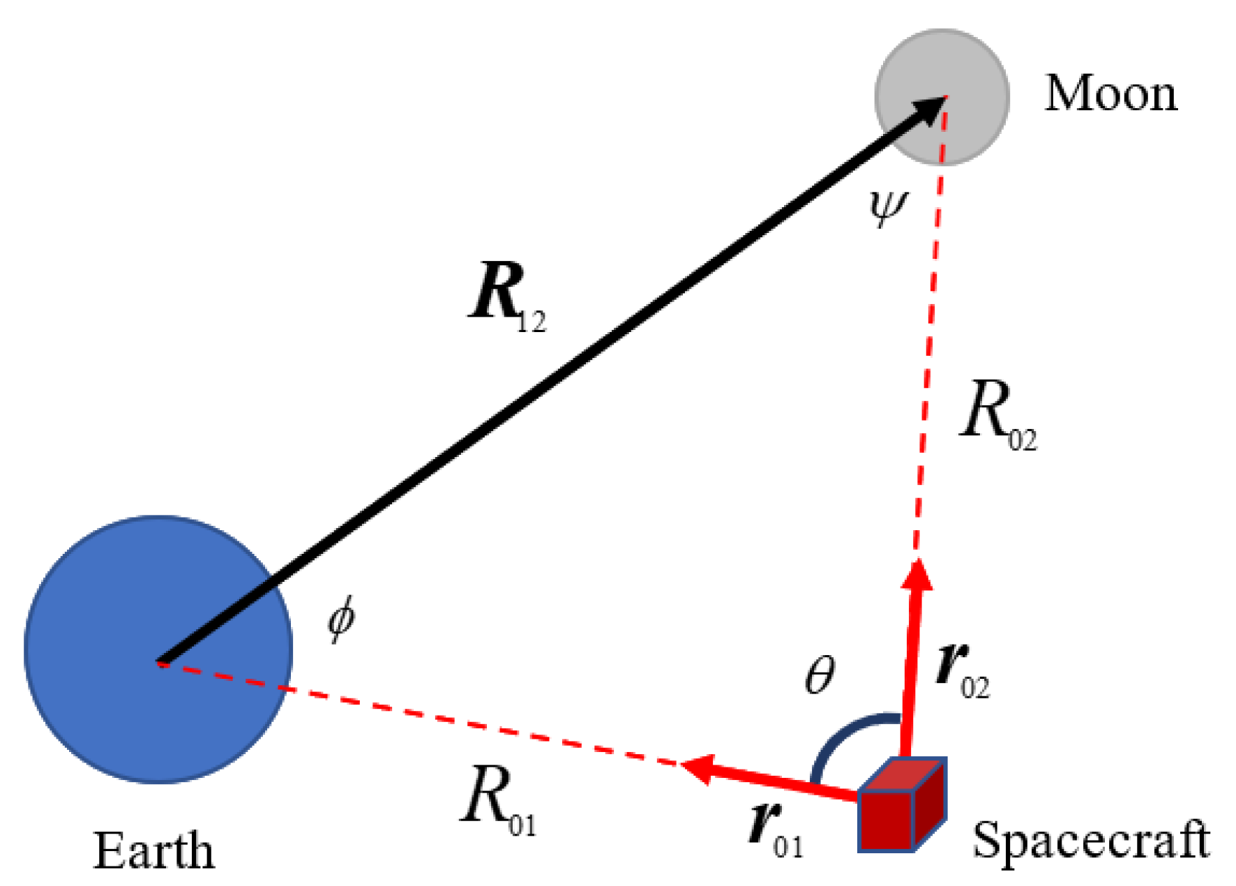
The triangulation technique was investigated to estimate the spacecraft position throughout the translunar trajectory. The fundamental principle relied on the geometric relationship formed between three bodies, the spacecraft, Earth, and Moon, as shown in Figure 2. This configuration naturally created a triangle where two vertices represented the known positions of the celestial bodies, which were obtained through ephemeris data, while the third vertex represented the spacecraft’s unknown position. With the spacecraft’s known attitude, it was assumed that the unit LoS vector measurements r 01 and r 02 to the Earth and Moon were extracted from camera images taken in the Geocentric Celestial Reference Frame (GCRF). This approach is suitable for cislunar navigation, where both celestial bodies remain consistently visible and their positions are well-defined through ephemeris data.
The relative position of the spacecraft and Earth or spacecraft and Moon can be calculated using the law of sines as given below.
R 01 = R 12 sin ψ sin θ
with
θ = cos 1 r 01 · r 02 ψ = cos 1 R 12 · r 02 R 12 .
The relative position vector from Earth to the spacecraft is
R 01 = R 01 r 01
When there is no error in the LoS measurements, the triangulation process is trivial. However, the presence of the noise causes inaccuracies in the position measurements obtained by triangulation process which need to be properly filtered. In order to take these errors in the position measurements into account, noise was added to the computed LoS vectors. The noisy LoS vectors are expressed as
r ˜ = r + ω
where the error has a Gaussian distribution:
ω N 0 3 × 1 , R Q M M .
The covariance with isotropic direction uncertainty is [26]
R Q M M = E ω ω T = σ θ 2 I 3 × 3 r r T
where σ θ = 0.001 is the standard deviation in the pointing direction of the unit LoS measurements.

5. Extended Kalman Filter

To analyze the performance of the proposed vision-based navigation system, an Extended Kalman Filter (EKF) was implemented using the sequential position measurements based on triangulation with noisy LoS vectors and the mathematical trajectory model of the spacecraft based on the previously mentioned three-body approach. The EKF, which extends the traditional Kalman Filter to handle nonlinearities in onboard real-time systems, is suitable for this application as it can effectively manage the nonlinear nature of spacecraft orbital dynamics [27]. Through the EKF’s recursive prediction and update steps, the navigation solution continuously refines its position estimates using the triangulation-based measurements from the observed celestial bodies. The initial conditions for the position estimates are derived from the triangulation measurements. Similarly, the initial velocity estimates were taken as the orbital velocity of the spacecraft in its circular orbit prior to the TLI maneuver. These initial conditions provide a reasonable starting point for the EKF to iteratively refine both position and velocity estimates throughout the trajectory. The flow diagram of the sequential EKF with corresponding model and measurement updates are shown in Figure 3. At each step of the filter, the measurement error covariance matrix R is dynamically updated based on the characteristics of the incoming measurements to account for variations in measurement noise.

6. Results and Discussion

The performance of the proposed triangulation technique was analyzed through extensive numerical simulations. The previously designed translunar trajectory was used as a baseline model to assess the effectiveness of the investigated triangulation method.
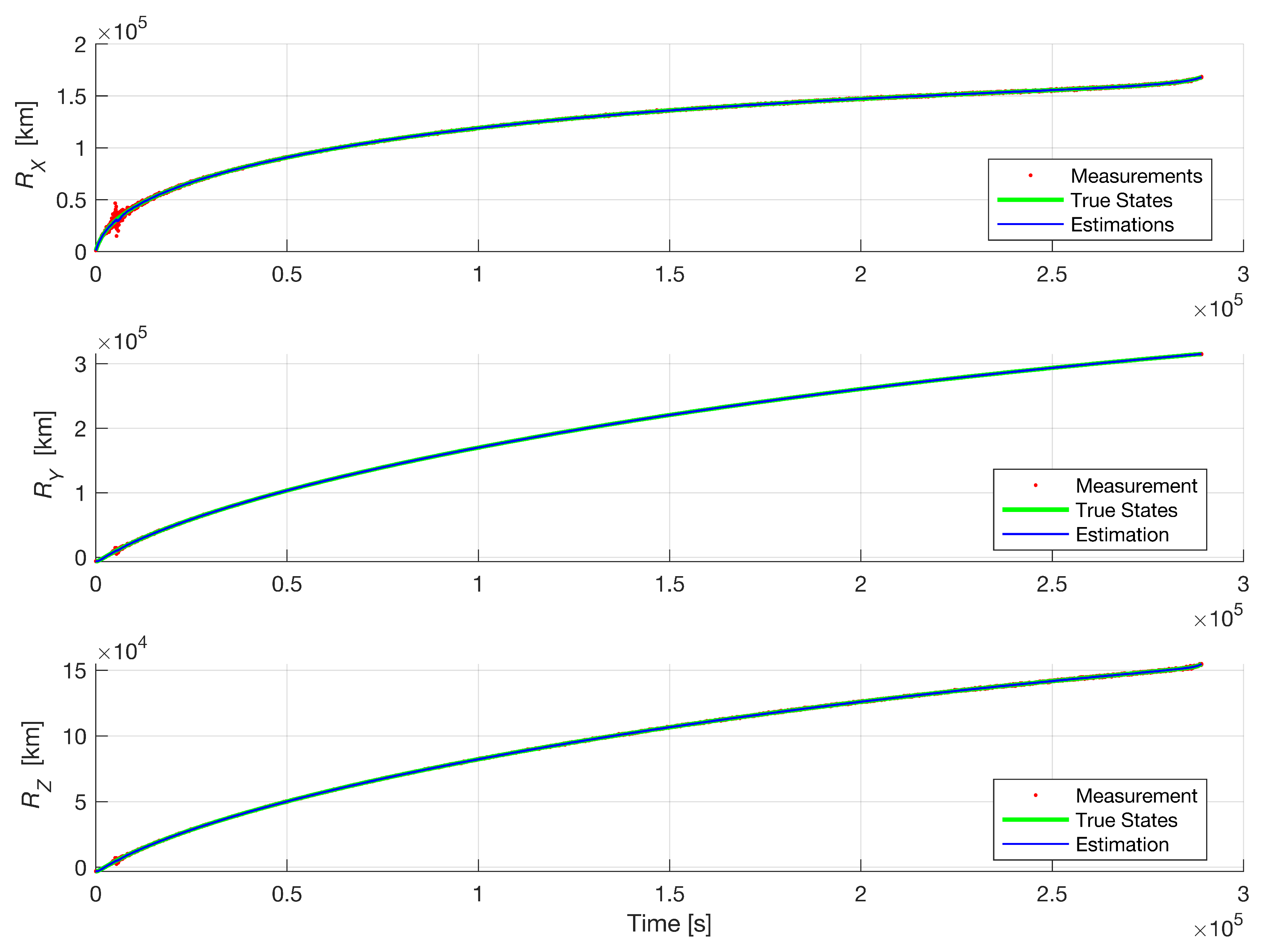
Position estimation results obtained by the EKF are presented in Figure 4. It may be observed from the given figure that the calculated position measurements from the triangulation between approximately t = 3000 and t = 10,000 seconds exhibited increased error variance. This phenomenon occurred because the angle between the LoS vectors to the Earth and Moon approached 180 in this time interval. When this occurred, the sine function in the denominator approached zero, leading to numerical instability in the triangulation calculations. This observation suggests that for more accurate results, the LOS vectors should not be aligned as parallel or anti-parallel. Despite the increased error variance in triangulation measurements, the EKF managed to provide more consistent position estimations.
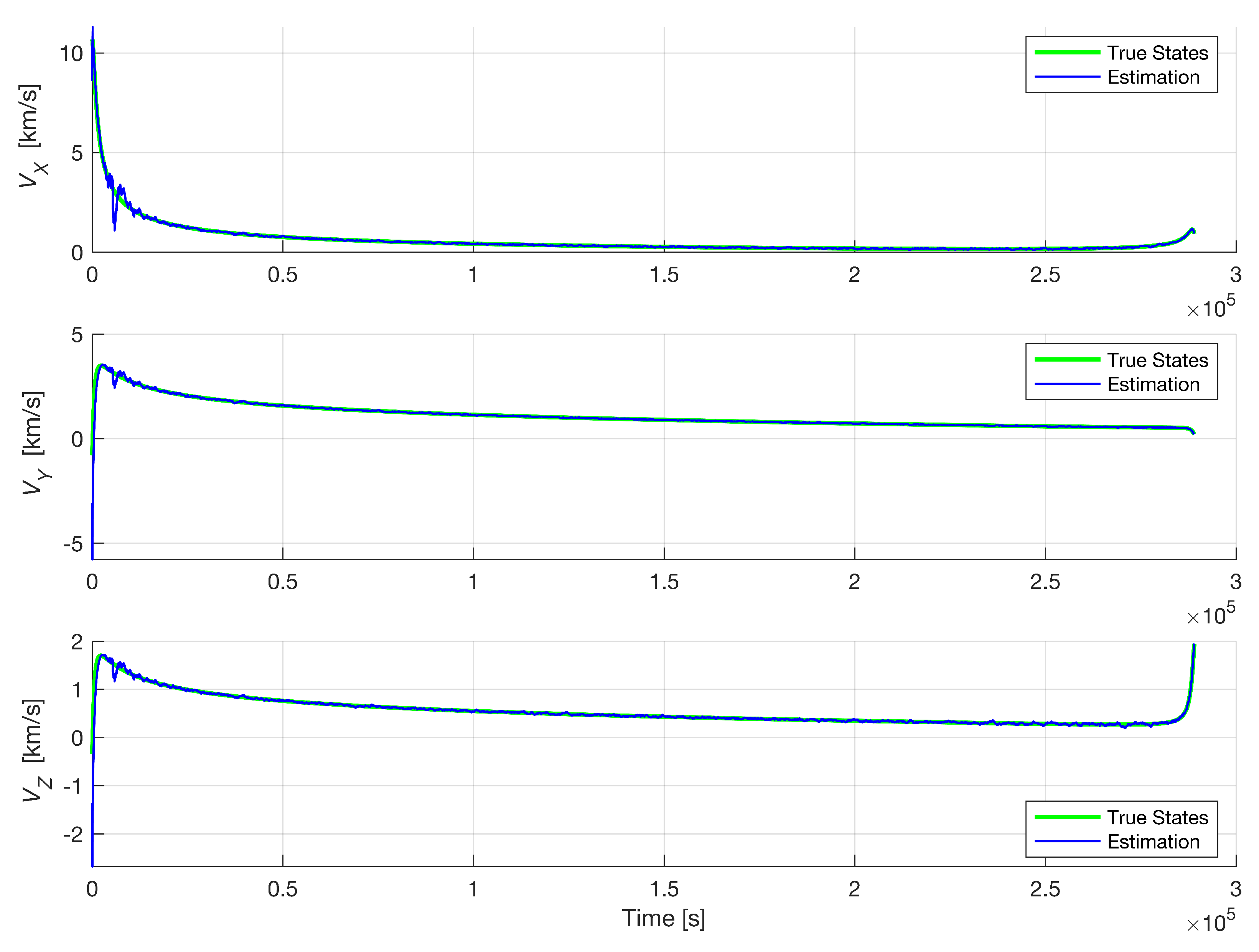
The velocity estimation results obtained by the EKF are presented in Figure 5. The estimated velocity aligns well with the true velocity states over the trajectory. This indicates that the EKF effectively utilized the measurements and the trajectory model to produce consistent velocity estimations. However, in the interval with the increased measurement error variance due to approaching an anti-parallel alignment in the LoS vectors, the velocity estimations exhibited fluctuations from the true values.
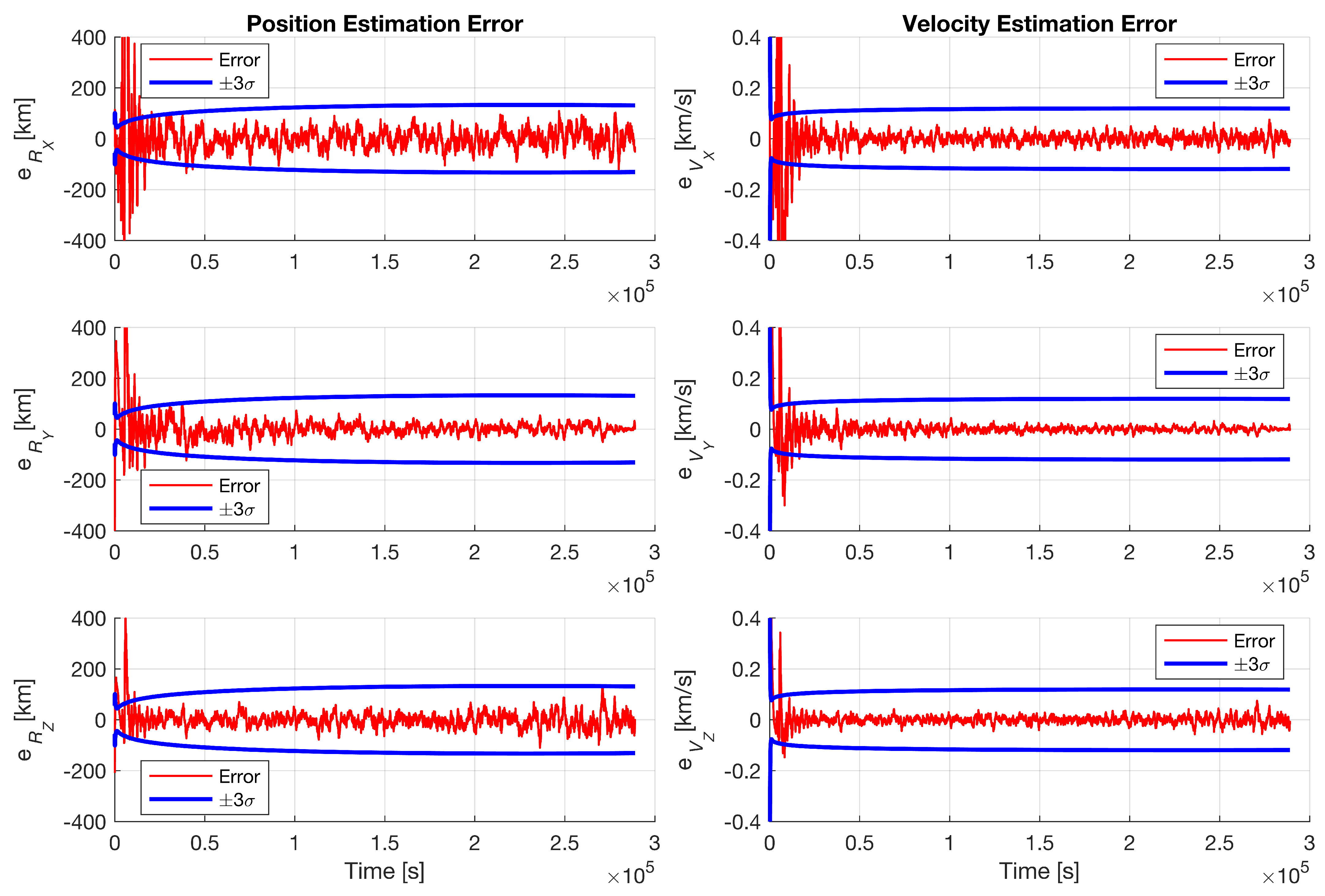
The EKF showed comparable performance in state estimation, with the estimations converging and remaining within the confidence intervals. The position and velocity estimation errors relative to the true states exhibited reasonable values throughout the trajectory. The position and velocity errors with their respective error covariances are presented in Figure 6, showing that the estimation errors remained bounded within the 3 σ confidence bounds except in the region of increased measurement error variance.
For accurate triangulation solutions, it is evident that the angle between LOS vectors should be aligned in such a way so as not to be close to zero or 180 to ensure numerical stability. This finding aligns with recent work [23]. Further analysis is required to address this limitation and develop strategies to mitigate its impact on navigation performance. In the same study, optimization in the case of multiple triangulation is proposed, but the effectiveness of it should be further analyzed with translunar trajectories in addition to interplanetary trajectories.

7. Conclusions

A vision-aided navigation method for translunar missions based on celestial triangulation using the Earth and Moon as reference celestial bodies is presented. The sequential measurements obtained by triangulations were fed into EKF which combined the measurements with a mathematical trajectory model to provide continuous state estimation. The following may be concluded. The triangulation method using LoS vectors from the spacecraft to two celestial bodies provides an effective means of position estimation for translunar trajectories. The EKF demonstrated satisfactory performance in state estimation, with results showing convergence and maintenance within confidence intervals. The geometry of the LOS vectors impacted estimation accuracy significantly when the LoS vectors approached parallel or anti-parallel alignment. The integration of IMU measurements with visual observations provides a robust navigation solution that helps mitigate error accumulation in pure IMU navigation.

Author Contributions

Conceptualization, methodology, validation, investigation, and writing—original draft preparation, A.M.; writing—review and editing and supervision, H.E.S. and O.T. All authors have read and agreed to the published version of the manuscript.

Funding

This research received no external funding.

Institutional Review Board Statement

Not applicable.

Informed Consent Statement

Not applicable.

Data Availability Statement

The data presented in this study are included in the article. Further inquiries can be directed to the corresponding author.

Acknowledgments

A. Muratoglu thanks the TUBITAK 2214-A International Doctoral Research Fellowship Programme for supporting his research at IfP, University of Stuttgart. This work was carried out as a part of a PhD thesis at METU by A. Muratoglu under the supervision of H. E. Söken.

Conflicts of Interest

The authors declare no conflicts of interest.

References

  1. Yüksel, M.; Roehr, T.M.; Jankovic, M.; Brinkmann, W.; Kirchner, F. A reference implementation for knowledge assisted robot development for planetary and orbital robotics. Acta Astronaut. 2023, 210, 197–211. [Google Scholar] [CrossRef]
  2. Trawny, N.; Mourikis, A.I.; Roumeliotis, S.I.; Johnson, A.E.; Montgomery, J.F. Vision-aided inertial navigation for pin-point landing using observations of mapped landmarks. J. Field Robot. 2007, 24, 357–378. [Google Scholar] [CrossRef]
  3. Cui, P.; Gao, X.; Zhu, S.; Shao, W. Visual navigation based on curve matching for planetary landing in unknown environments. Acta Astronaut. 2020, 170, 261–274. [Google Scholar] [CrossRef]
  4. Hesch, J.A.; Kottas, D.G.; Bowman, S.L.; Roumeliotis, S.I. Consistency analysis and improvement of vision-aided inertial navigation. IEEE Trans. Robot. 2013, 30, 158–176. [Google Scholar] [CrossRef]
  5. Christian, J.A. A tutorial on horizon-based optical navigation and attitude determination with space imaging systems. IEEE Access 2021, 9, 19819–19853. [Google Scholar] [CrossRef]
  6. Cassinis, L.P.; Fonod, R.; Gill, E. Review of the robustness and applicability of monocular pose estimation systems for relative navigation with an uncooperative spacecraft. Prog. Aerosp. Sci. 2019, 110, 100548. [Google Scholar] [CrossRef]
  7. Johnson, A.E.; Montgomery, J.F. Overview of terrain relative navigation approaches for precise lunar landing. In Proceedings of the 2008 IEEE Aerospace Conference, Big Sky, MT, USA, 1–8 March 2008; IEEE: Piscataway, NJ, USA, 2008; pp. 1–10. [Google Scholar]
  8. Cocaud, C.; Kubota, T. SLAM-based navigation scheme for pinpoint landing on small celestial body. Adv. Robot. 2012, 26, 1747–1770. [Google Scholar] [CrossRef]
  9. Christian, J.A.; Hong, L.; McKee, P.; Christensen, R.; Crain, T.P. Image-based lunar terrain relative navigation without a map: Measurements. J. Spacecr. Rocket. 2021, 58, 164–181. [Google Scholar] [CrossRef]
  10. Maass, B.; Woicke, S.; Oliveira, W.M.; Razgus, B.; Krüger, H. Crater navigation system for autonomous precision landing on the moon. J. Guid. Control. Dyn. 2020, 43, 1414–1431. [Google Scholar] [CrossRef]
  11. Chen, Z.; Jiang, J. Crater detection and recognition method for pose estimation. Remote Sens. 2021, 13, 3467. [Google Scholar] [CrossRef]
  12. Johnson, A.; Aaron, S.; Chang, J.; Cheng, Y.; Montgomery, J.; Mohan, S.; Schroeder, S.; Tweddle, B.; Trawny, N.; Zheng, J. The lander vision system for mars 2020 entry descent and landing. Guid. Navig. Control 2017, 2017, 159. [Google Scholar]
  13. Johnson, A.E.; Cheng, Y.; Trawny, N.; Montgomery, J.F.; Schroeder, S.; Chang, J.; Clouse, D.; Aaron, S.; Mohan, S. Implementation of a Map Relative Localization System for Planetary Landing. J. Guid. Control. Dyn. 2023, 46, 618–637. [Google Scholar]
  14. Rebordão, J. Space optical navigation techniques: An overview. In Proceedings of the 8th Iberoamerican Optics Meeting and 11th Latin American Meeting on Optics, Lasers, and Applications, Porto, Portugal, 22–26 July 2013; SPIE: Bellingham, WA, USA, 2013; Volume 8785, pp. 29–48. [Google Scholar]
  15. Christian, J.A. Accurate planetary limb localization for image-based spacecraft navigation. J. Spacecr. Rocket. 2017, 54, 708–730. [Google Scholar]
  16. Adams, V.H.; Peck, M.A. Interplanetary optical navigation. In Proceedings of the AIAA Guidance, Navigation, and Control Conference, San Diego, CA, USA, 4–8 January 2016. [Google Scholar]
  17. Adams, V.H.; Peck, M.A. Lost in space and time. In Proceedings of the AIAA Guidance, Navigation, and Control Conference, Grapevine, TX, USA, 9–13 January 2017. [Google Scholar]
  18. Franzese, V.; Di Lizia, P.; Topputo, F. Autonomous optical navigation for lumio mission. In Proceedings of the 2018 Space Flight Mechanics Meeting, Kissimmee, FL, USA, 8–12 January 2018; AIAA: Reston, VA, USA, 2018; p. 1977. [Google Scholar]
  19. Franzese, V.; Di Lizia, P.; Topputo, F. Autonomous optical navigation for the lunar meteoroid impacts observer. J. Guid. Control. Dyn. 2019, 42, 1579–1586. [Google Scholar]
  20. Li, C.; Zheng, Y.; Li, Z.; Yu, L.; Wang, Y. A New Celestial Positioning Model Based on Robust Estimation. In Proceedings of the China Satellite Navigation Conference (CSNC) 2013 Proceedings, Wuhan, China, 15–17 May 2013; Lecture Notes in Electrical Engineering; Springer: Berlin/Heidelberg, Germany, 2013; Volume 245, pp. 479–487. [Google Scholar]
  21. Raymond Karimi, R.; Mortari, D. Interplanetary autonomous navigation using visible planets. J. Guid. Control. Dyn. 2015, 38, 1151–1156. [Google Scholar]
  22. Broschart, S.B.; Bradley, N.; Bhaskaran, S. Kinematic approximation of position accuracy achieved using optical observations of distant asteroids. J. Spacecr. Rocket. 2019, 56, 1383–1392. [Google Scholar]
  23. Henry, S.; Christian, J.A. Absolute triangulation algorithms for space exploration. J. Guid. Control. Dyn. 2023, 46, 21–46. [Google Scholar]
  24. Chen, X.; Sun, Z.; Zhang, W.; Xu, J. A novel autonomous celestial integrated navigation for deep space exploration based on angle and stellar spectra shift velocity measurement. Sensors 2019, 19, 2555. [Google Scholar] [CrossRef]
  25. Christian, J.A. StarNAV: Autonomous optical navigation of a spacecraft by the relativistic perturbation of starlight. Sensors 2019, 19, 4064. [Google Scholar] [CrossRef]
  26. Shuster, M.D.; Oh, S.D. Three-axis attitude determination from vector observations. J. Guid. Control 1981, 4, 70–77. [Google Scholar]
  27. Chiaradia, A.P.M.; Kuga, H.K.; Prado, A.F.B.d.A. Onboard and Real-Time Artificial Satellite Orbit Determination Using GPS. Math. Probl. Eng. 2013, 2013, 530516. [Google Scholar]
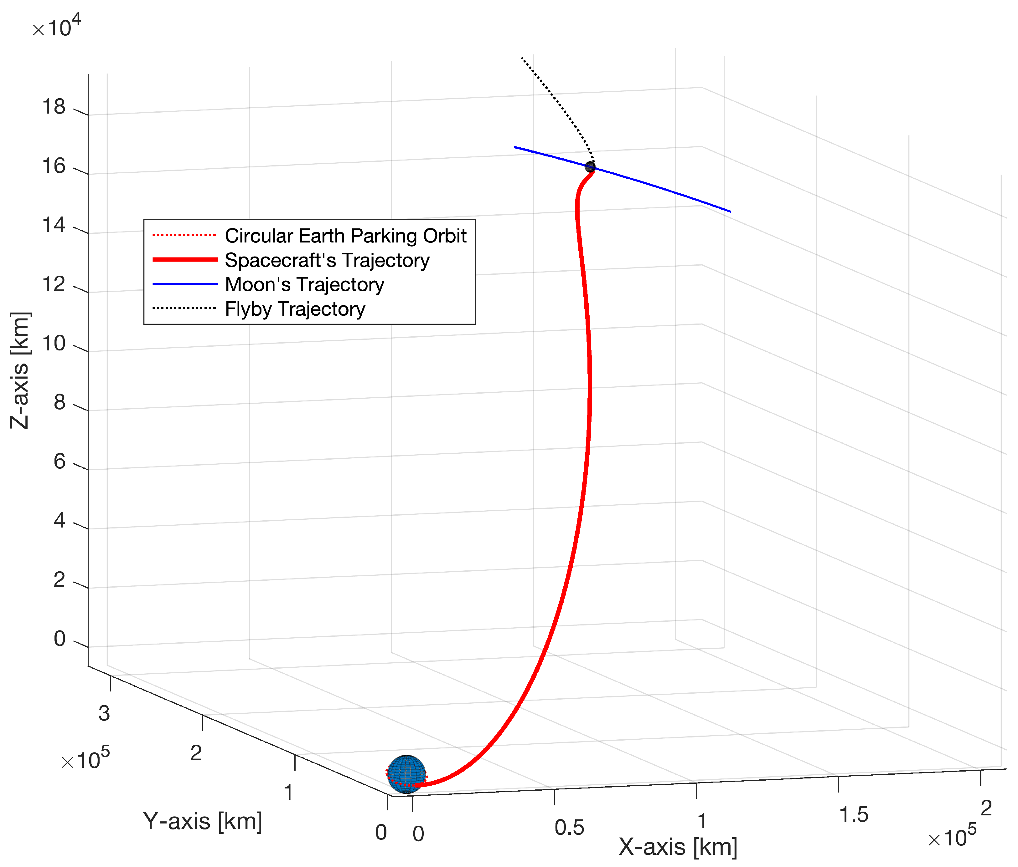
Figure 1. The designed trajectory of the spacecraft from a circular Earth orbit of an altitude of 400 km to be inserted into a circular Moon orbit of an altitude of 100 km is shown in a Geocentric Celestial Reference Frame (GCRF).
Engproc 90 00027 g001
Figure 2. The triangle with the Earth and Moon at known vertices.
Engproc 90 00027 g002
Figure 3. The EKF flow diagram.
Engproc 90 00027 g003
Figure 4. Position estimation results given with triangulation measurements and the true position states. The green line shows the designed true trajectory, the red points indicate the triangulation results of the measurements, and the blue line is the estimated trajectory.
Engproc 90 00027 g004
Figure 5. Velocity estimation results with the true velocity states. The green line shows the designed true trajectory and the blue line shows the estimated velocity through the trajectory.
Engproc 90 00027 g005
Figure 6. Errors for the position and velocity components of the state estimations and their associated 3 σ boundaries.
Engproc 90 00027 g006
Disclaimer/Publisher’s Note: The statements, opinions and data contained in all publications are solely those of the individual author(s) and contributor(s) and not of MDPI and/or the editor(s). MDPI and/or the editor(s) disclaim responsibility for any injury to people or property resulting from any ideas, methods, instructions or products referred to in the content.