Proceeding Paper

Toward Sustainable Space Exploration: Designing an AI-Powered Modular Toolbox for Future Planetary Exploration †

1
DFKI GmbH, Robert Hooke Str.1, 28359 Bremen, Germany
2
Robotics Research Group, University of Bremen, 28359 Bremen, Germany
*
Author to whom correspondence should be addressed.
Presented at the 14th EASN International Conference on “Innovation in Aviation & Space Towards Sustainability Today & Tomorrow”, Thessaloniki, Greece, 8–11 October 2024.
Eng. Proc. 2025, 90(1), 26; https://doi.org/10.3390/engproc2025090026
Published: 12 March 2025

Abstract

The possibilities for using modular space robot systems are constantly growing. To provide individual solutions for the requirements of different missions, modular reconfigurable building blocks can be used. This paper presents the MODKOM toolbox, including both hardware and software, with the intention to provide reusable components for use in space applications. It is populated with newly developed hardware and software components and their inter-connections. A semantic graph database was used to build the fundamentals of the toolbox, and it enables ontology-based mission planning and reasoning. Some hardware components of the toolbox have already been successfully used for the construction of two different robot systems.

1. Introduction

With the increasing technical possibilities of robotics systems, future space missions can and will become more complex. Missions will have multiple goals, such as exploration, sample and return, or setting up infrastructure for communication or monitoring. These goals require different capabilities of the involved robotic systems.
When using robot systems with a modular design, it is possible to expand systems with modules, provided that a corresponding electromechanical interface is available. In this way, system features can be expanded during a mission. For example, a module can be equipped with a camera. If a robot requires an additional camera during a mission, it can be equipped with the camera module. In this way, complex mission scenarios can be set up with individual modules. Another possibility is that defective modules can be replaced during a mission. Thus, a modular robot design provides the best flexibility and reusability of robotic resources, which is of high importance due to the high transportation cost in space missions.
Different levels of modularity have already been implemented in various spacecrafts, like the International Space Station, the Multimission Modular Spacecraft, or the Reconfigurable Operational Spacecraft for Science and Exploration [1]. Through using standardized and easily replaceable units that are interconnected by multifunctional interfaces, serviceability and resuability are enabled [2]. In addition, for planetary rovers, there are some concepts, like the modular robotic system presented by Hancher et al. [3], where many similar elements form one functional unit. Moreover, other works, as reviewed by Brunete et al. (2017) [4], show a likewise granularity.
For such systems that rely on a few building blocks, Tosun et al. [5] proposed a computer-aided compositional design tool. Although the integration of commercial off-the-shelf (COTS) components becomes more difficult, as there is already a vast amount of robot parts from many different manufacturers, integrating these components in a toolbox instead of starting from scratch saves development work [6].
Therefore, in MODKOM, the central aspect of the developed modular toolbox is to allow making use of COTS, as well as custom parts, as outlined in [7,8].
Via compatible interfaces and adapters, components can be combined to form new (sub-)systems, thus creating a reusable hierarchy of component designs. Specifically, this means that these modular subsystems are scalable to a certain degree and according to the mission requirements. To tackle the complexity issue of creating such systems, this paper presents methods and tools to support the user.

2. Toolbox

The toolbox, as a modular construction kit, models the system configuration for both the hardware and the software on the basis of reusable block components. Multiple components can be combined into more complex components by connecting them via interfaces that store information about the interface type, connectivity, multiplicity, and other data. Metadata about the components and interfaces, as well as the different compositions and configurations, is stored software-side in a database [7].
A graph-based, semantic system modeling approach forms the foundation of the toolbox. Based on this foundation, several software tools and graphical user interfaces (GUIs) were developed to create, modify, and deploy robot designs.

2.1. System Modeling and Database

The modeling layer is the core of the software framework, consisting of the xtypes-generator, xtypes, and xdbi libraries. The xtypes-generator defines the XType base class, which stores the properties and relationships between XTypes and generates project-specific models.
The xtypes library builds on this by defining key classes for modeling robotic systems (an overview of the classes and their relations is given in Figure 1, and the modeling mechanism is described in more detail in [8]).
The core class is ComponentModel, which represents the types of components and (possibly) their inner structure, while Components are specific, configured instances of these types. Similarly, InterfaceModels describe the types of interfaces, whereas Interfaces represent their instances. By connecting Interfaces e.g., the dataflow in a software network, the assembly information of a physical entity is encoded. Networks of Components and Interfaces can be reused across different systems, forming new ComponentModels.
XTypes also support the combination of abstract and concrete elements in system design. Templates can be created with abstract components, serving as placeholders for specific parts to be resolved later. This allows users to start with a flexible, high-level structure and to add concrete details when necessary.
Modules are created from ComponentModels when, e.g., a real physically existing robotic system is built from it, which is an example of system architecture description. When they are created, all of the abstract components inside are resolved and their configuration can only contain fully specified values. Therefore, they represent the so-called digital twins of their real-world counterparts. In software, this means that such a module is a digital twin of the running tasks inside the robot; in hardware, a module would be a digital twin of one of the actuators, e.g., the rear-left hip joint.
DynamicInterfaces represent interfaces, whose existence depends on the Component’s configuration and are transformed to Interfaces once the configuration is valid.
ExternalReferences link ComponentModels to additional resources like manuals, CAD data, simulations, or their actual software implementations.
The xdbi layer defines the interface and connects to the XRock-database, which stores XTypes and their relationships.
Multiple source databases and their order in lookup can be specified, but there can only be one destination database (where modifications can be made). This enables multiple users to access, store, and retrieve system designs, both locally and remotely, via REST API, thus facilitating the easy sharing and reuse of components.

2.2. Workflow and Tooling

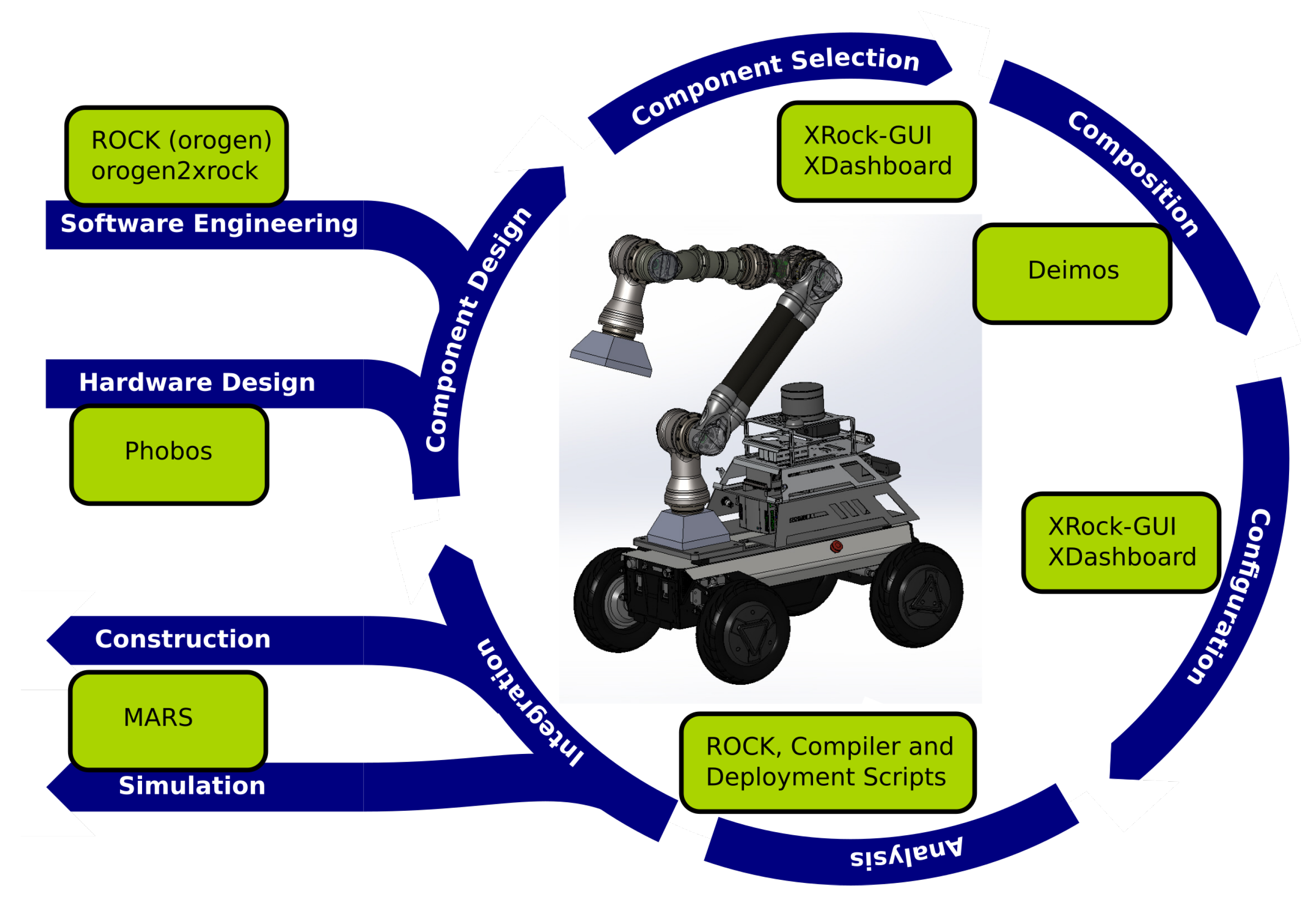
The workflow for designing a modular robotic system based on the toolbox can be depicted as the development cycle that is visible in Figure 2, with the final result being in the center. In the current state, the Robot Construction Kit (ROCK) is used as the source of software components and the backend to deploy the final runtime software [9]. However, most of the tools are framework-agnostic, so other frameworks can also be supported. In the following section, the developed tools are presented in order of the usage in the workflow cycle.
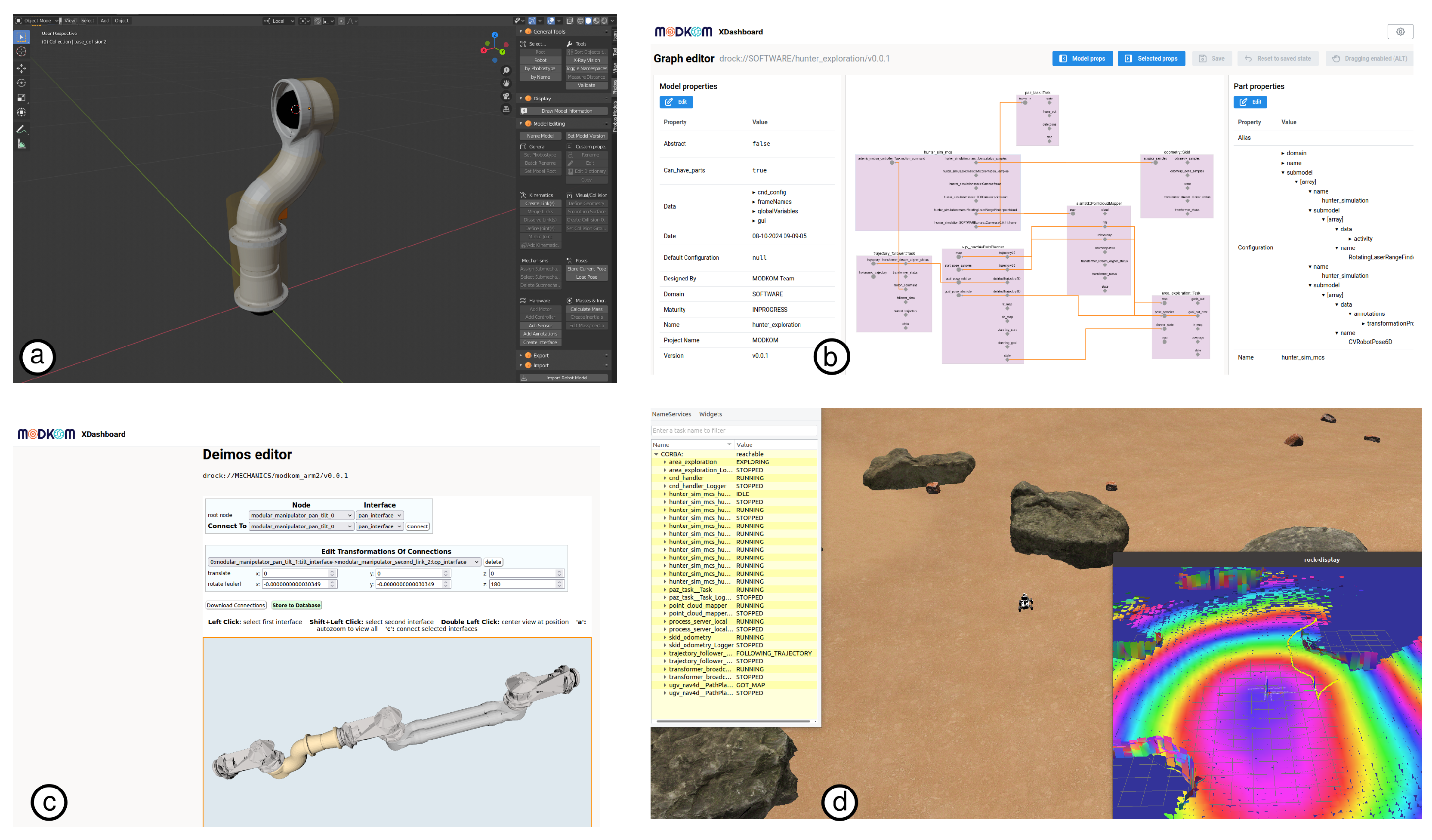
We start with the Component Design step, which lays out the new software and hardware components that are required for the target system (if they do not exist yet). The hardware models are created using Phobos, an open-source Blender add on, while the software component models are built with help of the oroGen tool set. Phobos allows users to annotate kinematic and visual models from CAD software with essential details like sensors, collision shapes, and interfaces. The new component models, including all relevant information, are added to the database using xdbi.
For special purposes, other tools for component design exist to support and simplify the creation of generic atomic ComponentModels and their interfaces, as well as to link abstract components to their concrete implementations. Abstract components are used to create model templates, which are resolved (e.g., by user choices) whenever a concrete version is requested.
Using XRock-GUI or XDashboard, the needed components are evaluated and selected for further composition in the Component Selection step. Since each component model, including both software and hardware, is stored in the database with its properties, the system designer is able to find the ones that best fit for the requirements. XDashboard is a central web interface where users can access all of the tools needed for creating and setting up components. Based on where they are in the process, tools like the XRock-GUI, Phobos, and other tools can be accessed right from the dashboard. New tools can be added easily as plugins, making the system flexible and expandable. The integrated Component Browser connects to the database where users can view and edit the entries. It lets users combine parts to create simple new models, allowing for the easy expansion of the system without complex connections. XRock-GUI is a desktop application that facilitates the creation and configuration of components within a new ComponentModel.
The components and their interfaces are displayed as editable nodes, allowing users to easily modify connections. The GUI ensures valid connections and supports configuration changes, including the global variables resolved at deployment, reducing manual edits and ensuring consistency.
Within the Composition step, the selected component models are composed into the new robotic system’s model to form both the hardware structure (mounting points and orientations, joints, and rigid structures), as well as the software needed to control it. Closely related is the Configuration step, in which the different components are configured to work together. This means that the software interfaces are connected, hardware properties updated, etc. The hardware composition utilizes the Deimos tool within XDashboard, while the software composition and configuration is conducted through XRock-GUI or XDashboard. Deimos is a 3D web app that helps users assemble and align hardware parts in a ComponentModel. This makes it easier to ensure all of the parts are correctly positioned relative to one another.
After the Analysis of the built architecture (such as, for example, the validity of connections, workspace analysis, etc.) an assembly manual for the hardware, as well as a compiled and executable software application, is constructed. In cases where the robotic system is to be simulated, the required artifacts—like URDFs and visuals—are generated, and the necessary application is compiled to execute it.
Finally, during the Integration phase, either the physical robotic system is constructed or the complete setup is run in the simulation, such as, for example, with MARS. Based on the tests with the robotic system or in simulation, there might be a need for adaptations, in which case, the workflow cycle starts anew.
To design and plan missions based on the available robotic systems and other objects, Mission-Planning was integrated, which triggers multiple phases of the workflow cycle. Based on the Moreorg ontology, the required capabilities and provided services of ComponentModels are specified within the xtypes ecosystem. The TemPl planning algorithm is integrated to choose the suitable systems for a mission and to provide a spatio-temporal plan, e.g., such as determining when a specific system has to perform certain tasks at a specific location or with certain objects. TemPl also plans the online reconfiguration of robotic systems to minimize the resources used, the load to carry, and the distances to travel. Both Moreorg and TemPl are described in detail in [10].

2.3. Hardware Toolbox Components

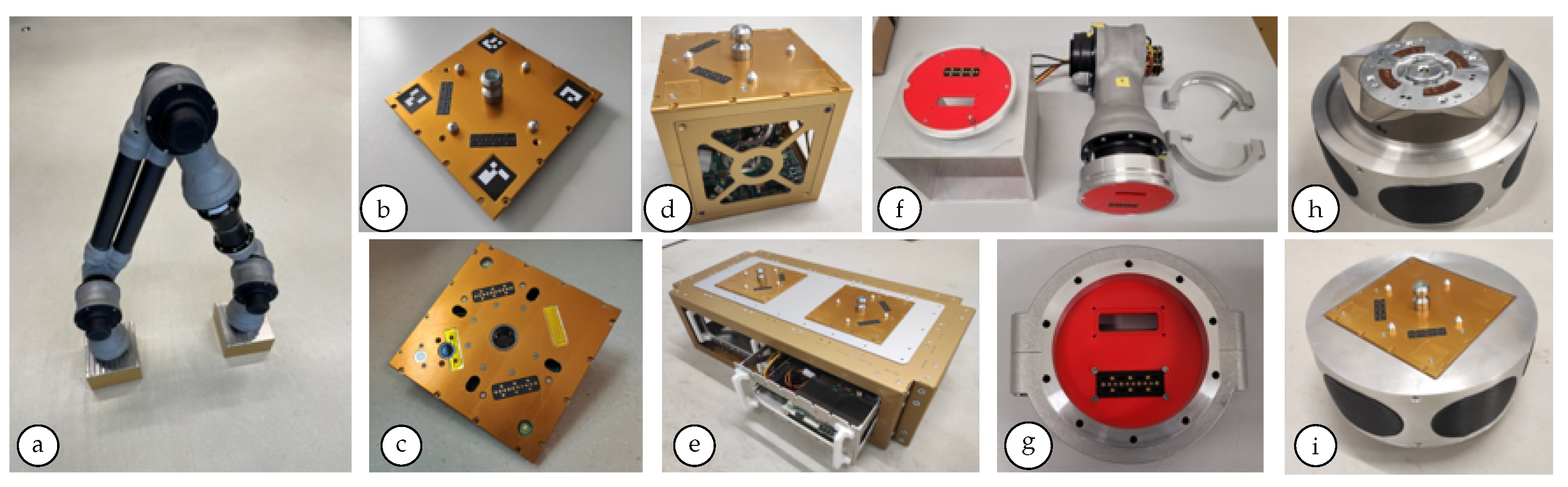
To reduce the costs and time needed when developing new systems, a toolbox with hardware modules was developed. A system can be configured and set up using these modules, and third-party components can be integrated. The modules can be connected to each other and to the third-party components via the so-called inter-modular interface (IMI) (see Figure 3g) and via the electro-mechanical interface–modular (EMI-MOD) (see Figure 3b,c). The IMI allows for a fast manual connection and disconnection between two components, and the EMI-MOD enables the online reconfiguration of the system to fulfill a variety of tasks and even extend its functionality by adding new modules or components as soon as they are equipped with at least one interface. Sustainability is ensured by the fact that defective modules can be quickly replaced via the EMI-MOD using the manipulator arm.
As one of the core elements, a modular 6 DOF manipulator arm was built *see Figure 3a). The design here directly follows the toolbox systematics, such that the manipulator is constructed from various functional units. The end effector of the arm is equipped with an EMI-MOD on both sides. This allows for the location of the manipulator to be changed during operation by bridging over from EMI-MOD to EMI-MOD and even changing the deployment system and its end effector payload according to the mission requirements. In MODKOM, the largest available version was built with a total length of 1628 mm, a mass of 15 kg, two pan tilt units with a 300 Nm peak, and an effective payload of 7 kg (a max. of 20 kg is theoretically possible). All of the joints were capable of 360° movement.
The EMI-MOD consists of an active and passive side (see Figure 3b,c), which mechanically connect the modules once they are equipped with one of them [11]. As a multifunctional interconnect, the EMI-MOD power and data transfer are ensured after a mechanical connection. For the docking process, by use of the manipulator arm, the EMI-MODs are equipped with LEDs, cameras, and markers to support the above-mentioned visual servoing process. Guiding pins help to assist the mating process. The overall dimensions are 150 × 150 × 60 mm.
The basic module (see Figure 3e) serves as a basic structural unit and is a carrier platform for electronic slide-in modules.
The basic module dimensions are 600 × 300 × 180 mm with a weight of 3.3 kg. Larger structures are possible by combining several modules with each other or by scaling one basic module to larger dimensions. The electronic modules, which are to be integrated in the basic module, are available as a modular system in widths of 60 mm, 120 mm, and 180 mm, with a maximum of up to 480 mm. These modules are equipped with an electrical plug-in system, which ensures the power supply and data transfer between the modules and with peripheral electronics. Passive EMI-MODs are fitted on top of the basic module.
Payload modules with dimensions of 150 × 150 × 150 mm combine two EMI-MODs (active and passive) with a standardized payload container (see Figure 3d). This allows one to easily add new function blocks for system extension and reconfiguration into the toolbox. For the proof-of-concept demonstration, it is envisioned to implement three distinct payload modules, like a camera module, gas sensor module, and battery module. The payload modules can be picked up by the manipulator arm via the EMI-MOD.
The inter-modular interface (IMI) (see 
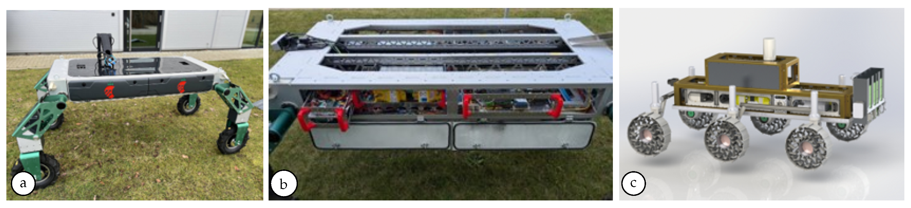
Figure 3g), with a height of 39 mm and a diameter of 151 mm, allows for a fast manual connection and disconnection between two components. Inside the flanges are freely configurable inlets that contain the components for power and high speed data transmission. The mechanical connection is statically designed for a torsion of 314 Nm. The selected COTS are the rover Hunter SE with a sensor carrier R&D Kit Pro from Agile X (see Figure 2), as well as one active and one passive iSSI® (see Figure 3h) from iBOSS GmbH.
To integrate the iSSI® within the mission, the active iSSI® is attached on an adapter together with the passive EMI-MOD (see Figure 3h,i). The adapter can be docked on the end effector of the manipulator arm with the passive EMI-MOD.
Another part of the toolbox is a quasi-direct drive motor for space applications, i.e., the DFKI-X2D joint. The main focus was on development with tests until Technology Readiness Level 5 was achieved, which is the next step toward space maturity [12].

3. Results

In the following section, the current results of the MODKOM project and its developments are presented.

Modeling a Robotic System

As shown in Section 2.2, the different tools in the standard MODKOM workflow were presented; here, an exemplary run through the different steps in this workflow—from component design to a running simulation—will be shown. At the beginning, a construction engineer passes a simplified version of the CAD design to the component designer. With the Phobos tool (see Figure 4) (1), the designer produces a mechanical model of the part, including the visuals, the collision bodies, the mechanical interfaces, etc. When stored, a component model, as well as a repository containing simulation relevant data, are stored within the database. The software component design process is not shown here because it is framework and CI (continuous integration) pipeline-dependent. Once all of the necessary parts have been designed, both the software and hardware parts are first selected and then composed to form (sub-)systems: the software components are mostly connected in a graph-like editor (2), and the hardware components are assembled in the Deimos tool (3). Only those interfaces/mounting points can be connected whose types are compatible, so only constructible systems can be built. During the composition process, the parameters of the parts, as well as the parameters of the resulting (sub-)system, can be configured. In the process, inter-dependent parameters can be calculated from global common values using a template engine. When all of the parameters have been chosen, the build process first analyzes the models (by checking the connections, calculating inter-dependent parameters, resolving abstract components to their concrete implementations, etc.) and then builds them. For hardware components, this means that all of the simulation relevant data are gathered and set up and/or the blueprint for construction is created; for software components, this means that executable software compositions are created (e.g., one for each robot behavior). As shown in Figure 4 (4), the exploration behavior (the autonomous map making of an unknown area) of the Hunter SE in a Mars-like simulation environment was captured as a result of the software build process.

4. Discussion and Conclusions

The toolbox components developed, the basic module above all, were already being utilized as a basis on other robot systems. The rover body of the SHIVAA robot (see Figure 5a), which was developed for the fully autonomous harvesting of strawberries grown in open fields (https://tinyurl.com/DFKI-SHIVAA-Video, accessed on 11 March 2025), consists in a scaled form of the basic module developed in MODKOM. As shown in Figure 5b, the body structure of the rover had the same height but had a length of 1700 mm and a width of 800 mm. The removable electronic modules had the same dimensions as in MODKOM, and they were used to house the necessary electronics and sensors for the SHIVAA robot.
The Artemis rover (https://tinyurl.com/DFKI-Artemis, accessed on 11 March 2025), which was developed for the DLR Spacebot Cup and us now involved in the VaMEx3 projects to collaborate within a robotic swarm, was rebuilt and received a rover body consisting of three MODKOM basic modules with the necessary electronic plug-in modules (see Figure 5c).
The described AI-powered modular toolbox is suitable for assembling the (sub-)systems from existing modular components that are required for a respective mission. The developed hardware, which can be gradually supplemented by either self-developed components or by COTS, as well as the specially developed software tools, help with this. With the help of IMI and EMI-MOD, all of the components can be combined with each other accordingly, both as a one-off fix and during an ongoing mission. Sustainability is ensured by the fact that the modular components can expand the mission according to the adapted requirements during a mission. There is no need to build complex systems that have to be abandoned in the event of a failure. The modular components offer the possibility of replacing subsystems if they fail. Increasing reliability and supporting other frameworks, such as ROS [13], are the next development steps. Furthermore, besides the integration of AI methods for mission planning and online system reconfiguration, it is planned that AI will be used for general system composition and property detection, such as, for instance, via workspace analysis.

Author Contributions

Toolbox software, M.S., P.C., M.L., J.L., E.M. and F.K.; toolbox hardware, W.B., J.E., J.B. and M.Y. All authors have read and agreed to the published version of the manuscript.

Funding

This research was funded by the Federal Ministry for Economic Affairs and Climate Action and the German Aerospace Center (grant numbers 50RA2107 and 50RA2108, respectively).

Institutional Review Board Statement

Not applicable.

Informed Consent Statement

Not applicable.

Data Availability Statement

Data are contained within the article.

Conflicts of Interest

The authors declare no conflicts of interest. The funders had no role in the design of this study; in the collection, analyses, or interpretation of data; in the writing of the manuscript; or in the decision to publish the results.

References

  1. Rossetti, D.; Keer, B.; Panek, J.; Ritter, B.; Reed, B.; Cepollina, F. Spacecraft Modularity for Serviceable Satellites. In Proceedings of the AIAA SPACE 2015 Conference and Exposition, Reston, VA, USA, 13–18 September 2015. [Google Scholar]
  2. Post, M.A.; Yan, X.T.; Letier, P. Modularity for the future in space robotics: A review. Acta Astronaut. 2021, 189, 530–547. [Google Scholar] [CrossRef]
  3. Hancher, M.D.; Hornby, G.S. A modular robotic system with applications to space exploration. In Proceedings of the 2nd IEEE International Conference on Space Mission Challenges for Information Technology (SMC-IT’06), Pasadena, CA, USA, 17–20 July 2006; p. 8. [Google Scholar]
  4. Brunete, A.; Ranganath, A.; Segovia, S.; De Frutos, J.P.; Hernando, M.; Gambao, E. Current trends in reconfigurable modular robots design. Int. J. Adv. Robot. Syst. 2017, 14, 1–21. [Google Scholar] [CrossRef]
  5. Tosun, T.; Jing, G.; Kress-Gazit, H.; Yim, M. Computer-aided compositional design and verification for modular robots. In Robotics Research; Springer: Berlin/Heidelberg, Germany, 2017; Volume 1, pp. 237–252. [Google Scholar]
  6. Külz, J.; Mayer, M.; Althoff, M. Timor Python: A Toolbox for Industrial Modular Robotics. In Proceedings of the IEEE International Conference on Intelligent Robots and Systems (IROS), Detroit, MI, USA, 1–5 October 2023. [Google Scholar]
  7. Sonsalla, R.; Brinkmann, W.; Wiedemann, H.; Langosz, M.; Chowdhury, P.; Schulz, C.; Jankovic, M.; Stark, T.; Schilling, M.; Mulsow, N.A.; et al. Towards Modular Components as Building Blocks for Application-Specific Configurable Space Robots. In Proceedings of the 16th Symposium on Advanced Space Technologies in Robotics and Automation (ASTRA-2022), Noordwijk, The Netherlands, 1–2 June 2022. [Google Scholar]
  8. Wiedemann, H.; Schilling, M.; Chowdhury, P.; Brinkmann, W.; Kien, I.; Li, J.; Langosz, M.; Michelson, E. Enhancing Development of Modular Application-Specific Configurable Space Robots. J. Phys. Conf. Ser. (JPCS) 2024, 2716, 012094. [Google Scholar] [CrossRef]
  9. Wirkus, M.; Arnold, S.; Berghöfer, E. Online reconfiguration of distributed robot control systems for modular robot behavior implementation. J. Intell. Robot. Syst. 2020, 100, 1283–1308. [Google Scholar] [CrossRef]
  10. Roehr, T. Autonomous Operation of a Reconfigurable Multi-Robot System for Planetary Space Missions. Ph.D. Thesis, University of Bremen, Bremen, Germany, 2019. [Google Scholar]
  11. Yüksel, M.; Brinkmann, W.; Jankovic, M.; Küçüker, H.D.; Kirchner, F. Enhanced multifunctional interface for reconfigurability of robotic teams in planetary applications. In Proceedings of the 2024 IEEE International Conference on Robotics and Automation (ICRA), Yokohama, Japan, 13–17 May 2024; pp. 13509–13515. [Google Scholar]
  12. Eisenmenger, J.; Zhao, Z.; Kirchner, F. Development of Quasi-Direct Drive Motor for Walking Robots in Extraterrestrial Environments. Eng. Proc. 2025, 90, 99. [Google Scholar] [CrossRef]
  13. Stanford Artificial Intelligence Laboratory. Robotic Operating System. Available online: https://www.ros.org (accessed on 11 March 2025).
Figure 1. Schematic overview of the entity–relation diagram for xtypes.
Engproc 90 00026 g001
Figure 2. The workflow, including the tools, ranging from the component design, composition, and configuration to final integration.
Engproc 90 00026 g002
Figure 3. MODKOM modules. (a) manipulator arm, (b) EMI-MOD passive, (c) EMI-MOD active, (d) payload module, (e) basic module, (f) setup with IMI, (g) IMI, (h) adapter with active iSSI®, and (i) adapter with passive EMI-MOD.
Engproc 90 00026 g003
Figure 4. Screenshots of exemplary workflow sub-steps, starting with the design of the MODKOM manipulator part (a); the selection of needed components (which is same for both hardware and software); the composition of mechanical parts of the manipulator arm using Deimos (c); the composition of the software using the web-based graph editor (b); and the configuration and, finally, results (after analysis and compilation) in a simulation of the mobile robot’s exploration behavior (also showing the running sub tasks, as well as the generated map and exploration trajectory) in a Mars-like setting (d).
Engproc 90 00026 g004
Figure 5. Application of the MODKOM toolbox in other robot systems: (a) SHIVAA autonomous strawberry-picking robots, (b) SHIVA’s modular structure, and (c) the CAD model of the Artemis rover, version 2.
Engproc 90 00026 g005
Disclaimer/Publisher’s Note: The statements, opinions and data contained in all publications are solely those of the individual author(s) and contributor(s) and not of MDPI and/or the editor(s). MDPI and/or the editor(s) disclaim responsibility for any injury to people or property resulting from any ideas, methods, instructions or products referred to in the content.

