Abstract
Non-contact NDT methods that can provide fast, automated, in-line quality assurance information on the manufacturing and maintenance of large-scale, thin-walled aircraft parts are necessary for the implementation of thermoplastic CFRP in the next generation of aircraft. Infrared thermography (IRT) is a promising method to fill this gap. Here, the detection of flat bottom holes, inclusions, and interlaminar delaminations in fuselage skin is studied for two types of IRT and compared with ultrasound inspection. Unique to this work are three demonstrations of the potential of IRT to deliver a time-effective, automated inspection approach for large-scale, thin-walled thermoplastic CFRP aircraft parts.
1. Introduction
In the manufacturing of large-scale carbon fiber-reinforced polymer (CFRP) aircraft parts, any defects incurred during production can lead to considerable setbacks. The intricate nature of large-scale components poses challenges in ensuring precision and quality control throughout the manufacturing process, with scrap rates ranging up to 20%. Current quality assurance systems cannot provide fast, automated in-line inspections such that early detection of defects at single stage level is achieved, avoiding their propagation to the next manufacturing stages. NLR has an extensive track record on non-contact Non-Destructive Testing (NDT) methods based on optical sensors, such as 3D surface scanning, infrared thermography (IRT), and laser shearography [1,2]. The combination of these methods (termed multi-domain inspection) enables the assessment of the structural integrity of an aircraft’s outer surface in a short time, reducing inspection costs during production and Maintenance Repair and Overhaul (MRO) and the “down time” of the aircraft in the MRO sector.
In this work, non-contact NDT methods are evaluated with the directed goal of providing fast, automated, in-line quality assurance information on the manufacturing of large-scale, thin-walled aircraft parts. The two non-contact NDT methods evaluated here are both based on IRT, which monitors the heat radiation pattern on the surface of a part. The method employs light just above the visible part of the electromagnetic spectrum, in the range of about 2–14 μm. Passive and active IR techniques can be distinguished, but for NDT purposes, generally, the active technique is used. With active IR, the object is excited either by an external heat source or by mechanical vibrations. Material defects are then detected by the corresponding changes in the heat distribution pattern on the surface of the part. Thermographic techniques are well applicable in composite materials because of their relatively low thermal conductivity (<1 W/m·K), which implies a slow lateral heat flow with closely spaced isotherms, resulting in good defect resolution. IRT is capable of inspecting surface areas up to 1 m2 with a single exposure technique and detecting defects with sizes larger than the depth of the defect. In this work, two exposure techniques are evaluated: Optical Lock-In Thermography (OLT) and Long Pulse Thermography (LPT). The two techniques are distinguished by the method of exposing the inspected surface, via either a long pulse (15–60 s) for LPT, or a sinusoidal exposure for OLT, the frequency of which is tailored to the thermal diffusivity and thickness of the part. The suitability of these two non-contact NDT methods is tested first on flat bottom holes (FBHs) and then on two commonly occurring production defects in the fuselage skin: inclusions and interlaminar delaminations using ultrasound inspection (UT) as the baseline NDT technique. Finally, three demonstrations at a large scale are presented with the aid of the lower fuselage of the 8 m long by 4 m diameter thermoplastic (TP) CFRP Multifunctional Fuselage Demonstrator (MFFD), manufactured under the lead of Airbus [3] and its assembly jig.
2. Materials and Methods
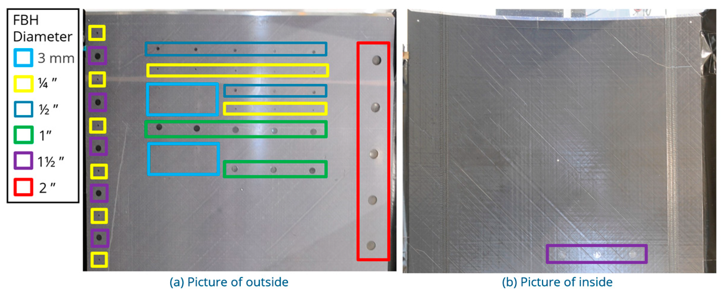
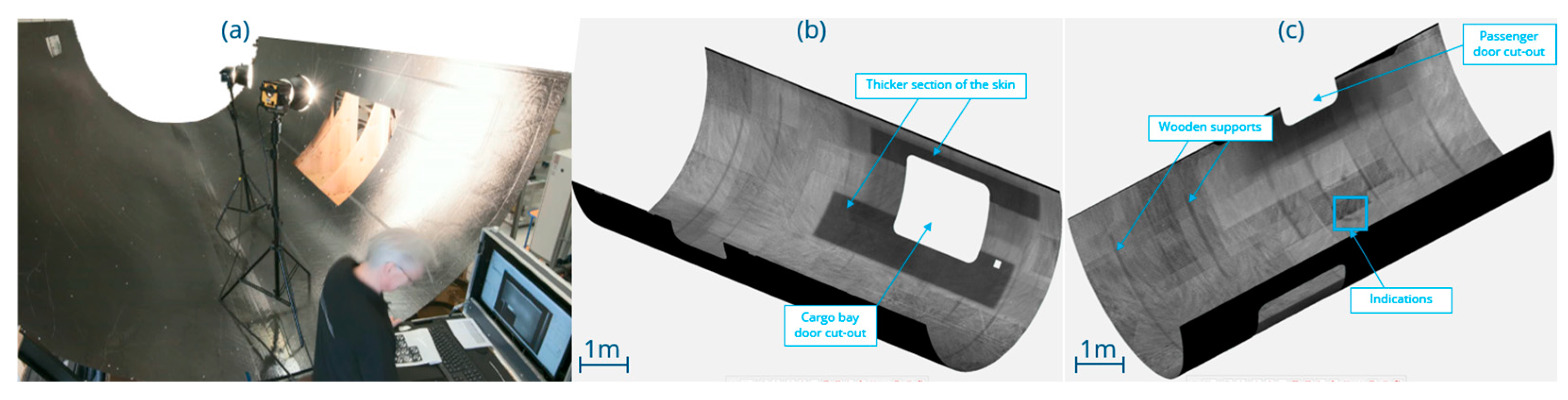
Three reference panels with artificial defects are used to determine the effectivity of OLT and LPT for the detection of defects in fuselage skin. The first panel, shown in Figure 1, is a TP CFRP (LM-PAEK) cargo bay door cut-out of the MFFD with varying thickness. FBHs have been drilled into the outside and inside surface at diameters ranging from 3 mm to 2”, at increasing depths from the surface. In this work, only the outside FBHs are studied, as the lower fuselage skin of the MFFD is inspected from the inside due to practical constraints.
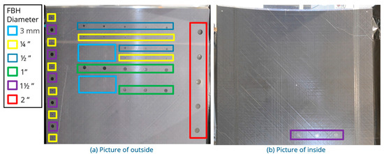
Figure 1.
Design of reference panel simulating TP CFRP fuselage skin with FBH defects, with (a) a picture of the outside (convex side) and (b) a picture of the inside (concave side).
The second and third panels shown in Figure 2 are TP CFRP (PEKK), which contain 4 steps with a thickness varying from approx. 9, 7, 4.5, to 2.25 mm. In one panel circular, artificial inclusions of materials likely to be found in a TP CFRP production environment have been inserted at varying depths from the outside surface as indicated in Figure 3a, with either a ½” or ¼” diameter. The third panel was intended to simulate interlaminar delaminations. Three sets of circular, artificial delaminations have been inserted at varying depths from the outside surface, as indicated in Figure 3b, with a ½” diameter.
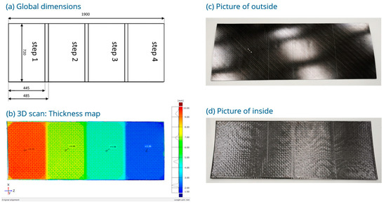
Figure 2.
Design of reference panels simulating TP CFRP fuselage skin with inclusions and interlaminar delaminations, with (a) global dimensions, (b) thickness map from a 3D scan, (c) picture of the outside (convex side), and (d) picture of the inside (concave side).
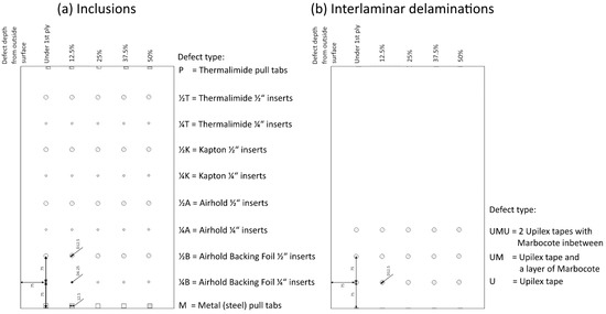
Figure 3.
Design of artificial defects in each step of the reference panels simulating TP CFRP fuselage skin with (a) artificial inclusions and (b) artificial interlaminar delaminations.
The following equipment is used in this work: For IRT inspections, an IR camera (Taurus 1310k (Cooled MWIR, 1280 × 1024 pixels, NETD < 28 mK, 25 mm lens, 3.4–4.9 µm wavelength)) is used. Excitation is performed using the Edevis OTVIS 4000 Thermography system, which uses two halogen lamps for optical excitation with a combined power of 4 kW. Data analysis is performed in DisplayIMG 7. Baseline ultrasonic C-scans at 5 MHz are performed with an Ultrasonic Sciences Ltd., Aldershot, UK, C-scan system, where the squirter/water-jet method is used in a through-transmission set-up. Data analysis is performed in USL scanner 4.46. A 3D structured light scanner (ATOS 5 MV1000) system is used to confirm the global dimensions of the reference panels and large-scale aircraft parts. Data analysis is performed with Zeiss Inspect 2022. Demonstrations at large scale are performed on the lower fuselage skin of the MFFD at NLR, Marknesse, the Netherlands, on the lower fuselage of the finished MFFD at Airbus ZAL, Hamburg, Germany, and automation of the IRT inspection is demonstrated on the gantry at SAMXL, Delft, the Netherlands, in the MFFD lower fuselage assembly jig.
3. Results and Discussion
The effectivity of two non-contact NDT IRT techniques at detecting FBHs, inclusions, and interlaminar delaminations in TP CFRP fuselage skin is studied in this section. After this, three demonstrations of IRT at scale are presented on the lower fuselage of the MFFD, manufactured under the lead of Airbus [3] and its assembly jig.
3.1. Detection of Defects in CFRP Fuselage Skin
3.1.1. Flat Bottom Holes (FBHs)
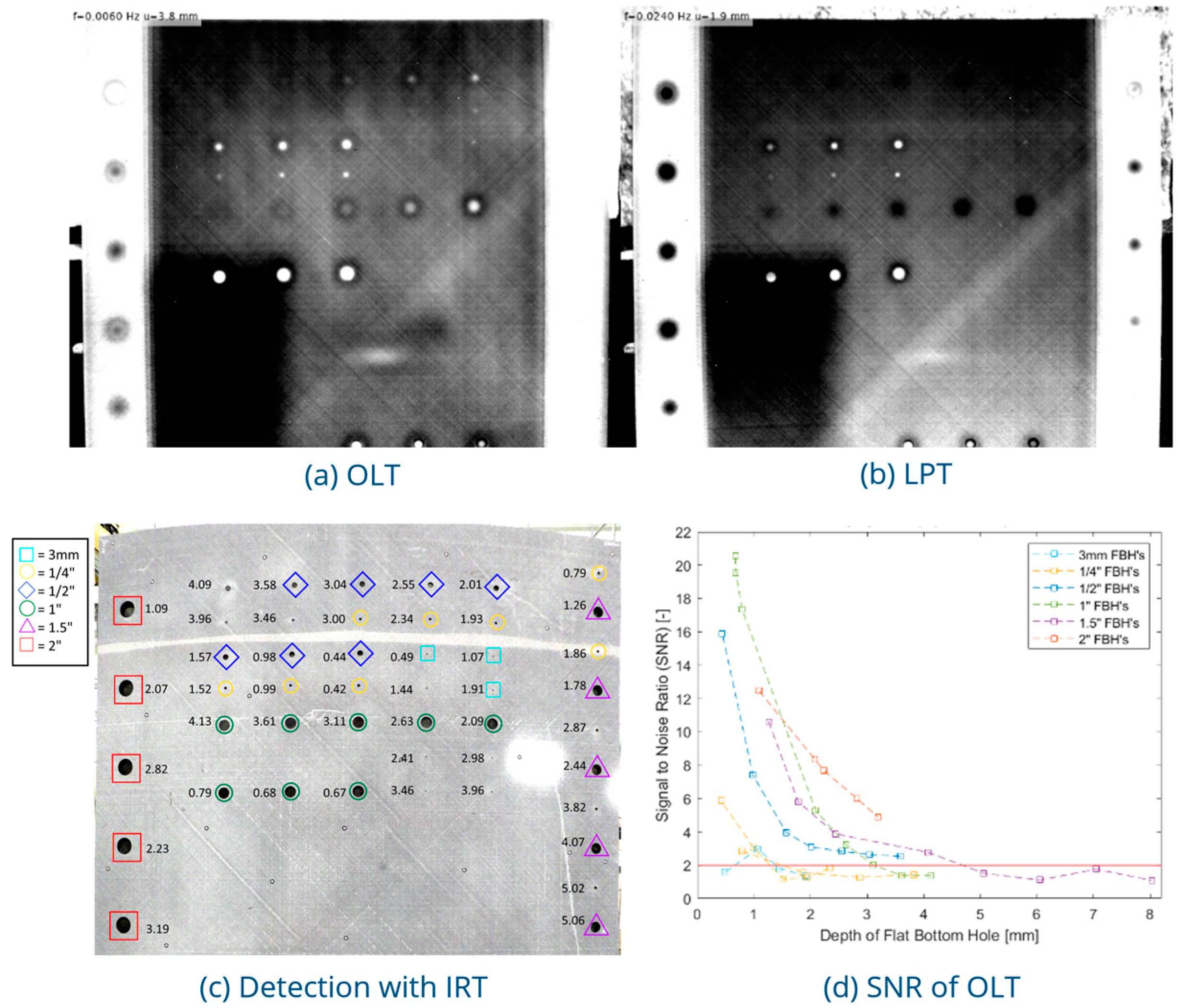
FBHs in the cargo bay door cut-out from the lower fuselage of the MFFD were used to optimize the settings of OLT and LPT inspections, as these defects are clearly visible and well-defined. FBHs of size ranging from 3 mm to 2 “were drilled into the outside surface of the panel, and inspected from the inside. An example of the OLT and LPT phase thermograms of the inside surface are given in Figure 4a and Figure 4b, respectively, where the LPT phase thermogram is generated from a Fast Fourier Transform (FFT) of the panel during heating (first period). The IRT inspections give a homogeneous view of the panel in which the different skin thicknesses can be observed. To optimize the settings of LPT inspections, the pulse length and recording time were varied. The pulse length was varied between 15 and 60 s. A pulse of 15 s resulted in a noisy image at low FFT frequencies, while a pulse of 60 s decreased detection in thin sections of the panel. The pulse length is set to 30 s to decrease noise and retain defect detection. Recording time was varied between 90 and 180 s. No additional information was gained from recording times longer than 90 s, as such LPT inspections are limited to a 90 s recording time. To optimize the settings for OLT inspections, the lowest frequency at which the deepest FBHs are first visible was determined. Frequencies are cut off at that point, as no additional information was gained from lower frequencies. A total of 10 frequencies were used to inspect the panel for a total measurement time of 15 min. While the majority of the defects can be visually detected (Figure 4c), the signal–noise ratio (SNR) of the defects shows a strong dependence on the size of the defect and the depth from the scanned surface. In Figure 4d, the maximum SNR of the OLT inspection of each defect is given. Small (size < ½”) and/or deep (depth > 5 mm) defects, while still visually detected, have an SNR < 2. For the thin sections of the panel, defects of size > ½” are reliably detected with an SNR > 2 down to 80% of the panel thickness, while for the thick sections, detection is only reliable down to 55% of the panel thickness. These settings for the OLT and LPT inspections are used in the remainder of this work.
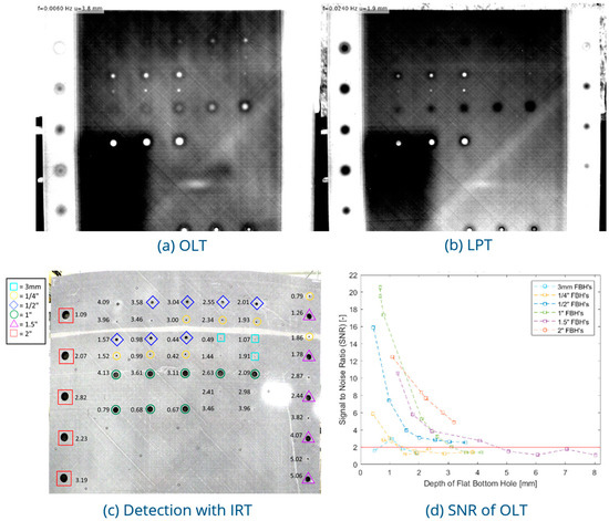
Figure 4.
MFFD cargo bay door cut-out reference panel with FBHs, with (a) an example of an OLT at f = 0.008 Hz, (b) an example of an LPT at f = 0.0240 Hz, and (c) a mirrored picture of the outside of the panel. FBH depth is written next to the defect. Detected defects encompassed by a shape; color/type of the shape indicates the FBH’s diameter, and (d) the SNR of the OLT, where the solid red line is drawn at an SNR of 2 indicating the threshold for reliable detection.
3.1.2. Inclusions
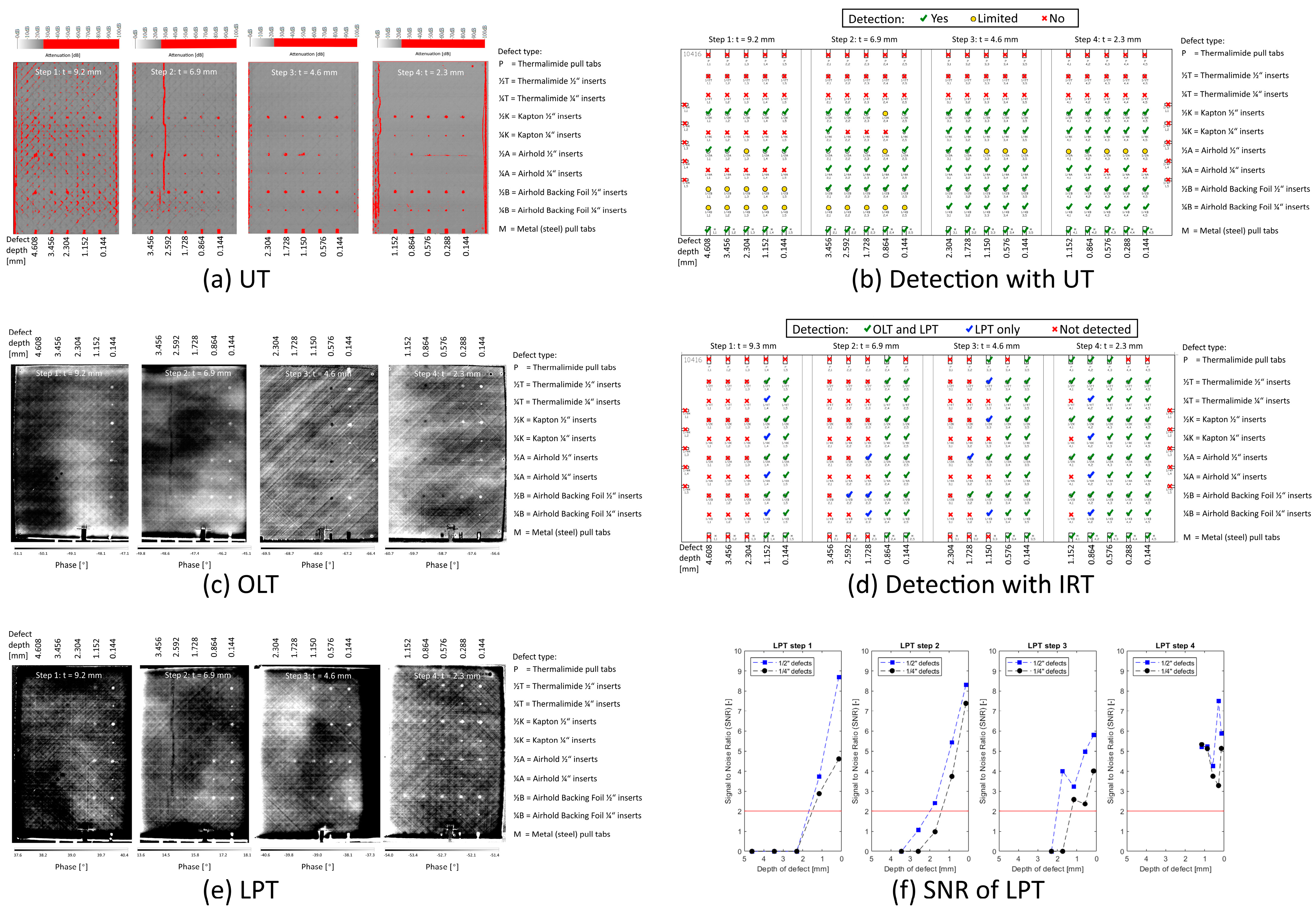
The next step is to assess the detection of foreign material in the fuselage skin. The detection of circular inclusions of diameter ¼” and ½” inserted in a CFRP reference is studied with IRT and compared to UT in Figure 5. The inserted materials are commonly found in a CFRP production environment. If the defect is detected with UT, see Figure 5a, via a 2 dB drop in the attenuation, a green checkmark is placed by its name, see Figure 5b. If the defect is visible, but detection is limited to an attenuation drop of less than 2 dB, a yellow circle is placed by its name, and if the defect is not detected, a red cross is placed by its name. From Figure 5b, it is clear that inclusions made of thermalimide are transparent to UT. In the thickest step 1, UT struggles to distinguish defects from the corrugated surface and symmetric layup of the CFRP panel. Most of the remaining defects are detected, with some smaller ¼” inclusions being missed. Examples of the OLT phase thermograms of the outside of the panel are given in Figure 5c at a modulation frequency of 0.013 Hz, 0.004 Hz, 0.008 Hz, and 0.145 Hz for steps 1–4, respectively, and examples of the LPT phase thermograms are given in Figure 5e. The detection of the inclusions with IRT is summarized in Figure 5d. The IRT inspections show a strong dependence on both the size and the depth of the defect, in line with the findings for the FBHs in Figure 4, where the LPT inspections fair better at detecting the smaller, deeper defects than OLT. The SNR of defects detected from LPT is summarized in Figure 5f, where only the maximum SNR of the LPT inspections is given for each defect. The inclusions can be reliably detected (with an SNR > 2), down to a depth of approx. 2 mm from the scanned surface, irrespective of the thickness of the step. The SNR of the ½” inclusions is larger than for the ¼”, indicating that these are more easily detected. UT outperforms LPT when it comes to the detection of inclusions at depths > 2 mm, although this limitation of LPT can be mitigated by inspecting the panel from both sides.
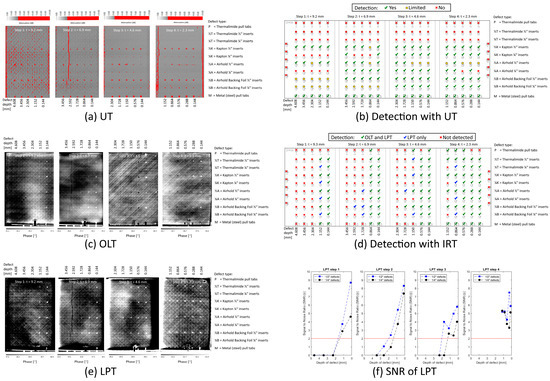
Figure 5.
Detection of artificial inclusions in a TP CFRP fuselage skin reference panel with (a) the UT baseline, (b) a schematic of the detection with UT, (c) an example of the OLT inspection, (d) a schematic of the detection with IRT, (e) an example of the LPT inspection, and (f) the maximum SNR of each defect in the LPT inspection, where the solid red line is drawn at an SNR of 2 indicating the threshold for reliable detection.
3.1.3. Interlaminar Delaminations
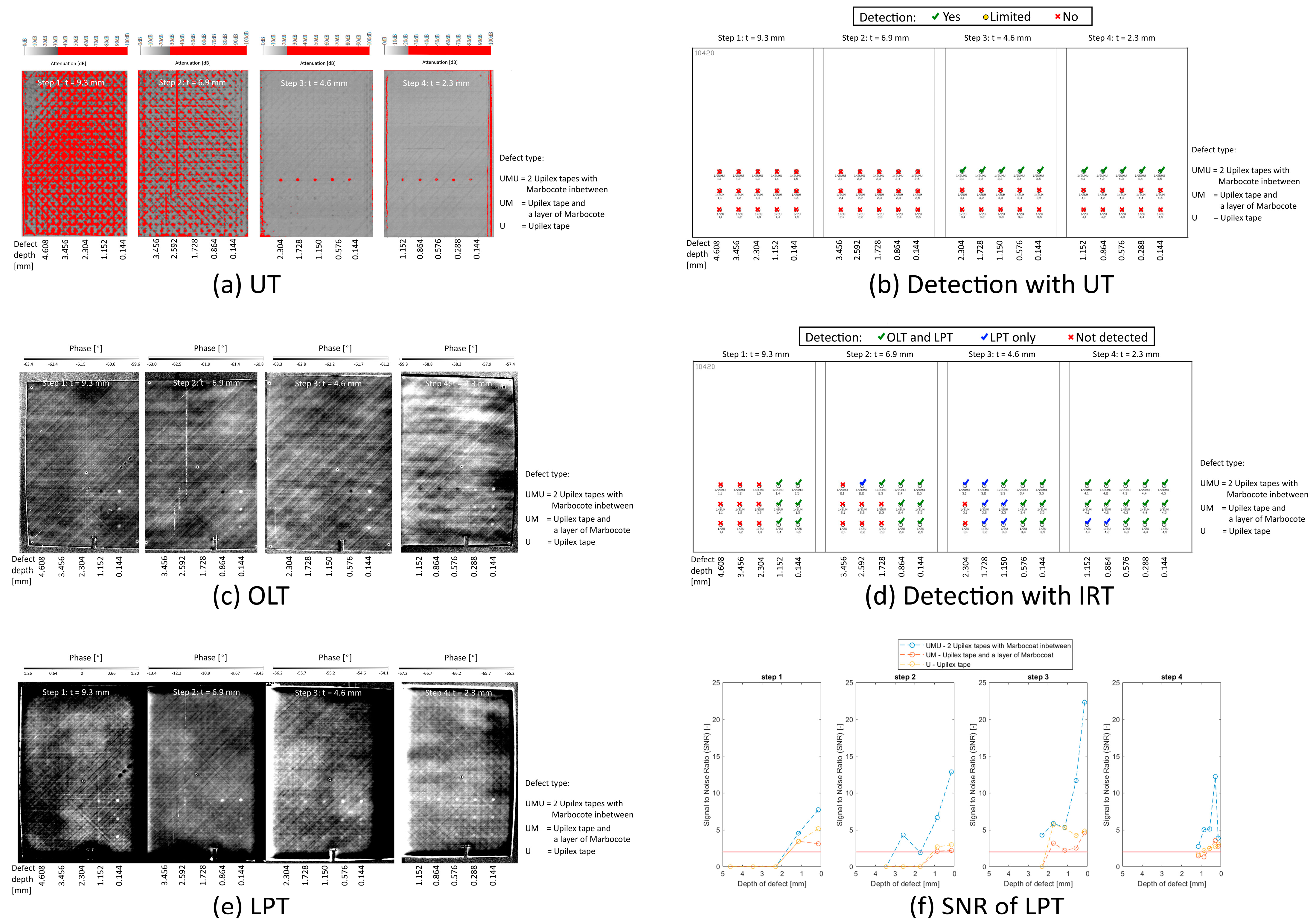
The final defect type studied here is interlaminar delamination in fuselage skin. An attempt was made to artificially generate these in a reference panel, see Figure 6. From the UT inspection, shown in Figure 6a, only the top row of the inserted defects in the thinnest two steps (3 and 4) can be confirmed to have successfully generated a delamination. The detection of these defects is confirmed via a 2 dB drop in the attenuation, see Figure 6b where only these defects have a green checkmark. The thicker steps (1 and 2) suffer from local porosity in a pattern consistent with the layup of the carbon fiber tape, obscuring the delamination defects from UT. The artificial defects in the top row (UMU) of step 3 and at 0.288 mm from the surface in step 4 have an SNR > 40, indicating that these are representative of actual interlaminar delaminations. Examples of the OLT phase thermograms of the outside of the panel are given in Figure 6c at a modulation frequency of 0.145 Hz, 0.107 Hz, 0.209 Hz, and 0.145 Hz for steps 1–4, respectively, and examples of the LPT phase thermograms are given in Figure 6e. The detection of the delaminations with IRT is summarized in Figure 6d. The IRT inspections, again, show a strong dependence on the depth of the defect, where LPT inspections can detect defects deeper from the scanned surface than OLT. While delaminations in steps 1 and 2 are detected by both OLT and LPT, the porosity in the panel is missed. The SNR of the delaminations detected from LPT is summarized in Figure 6f, where only the maximum SNR of the LPT inspections is given for each defect. The actual delaminations (UMU defects, top row) can be reliably detected (with an SNR > 2), down to a depth of approx. 2 mm from the scanned surface, irrespective of the thickness of the step. Delaminations with high SNR (~50) in UT, such as the defect 0.288 mm from the surface of step 4 and the defect 1.728 mm from the surface of step 3, similarly show high SNR (~5) in the LPT.

Figure 6.
Detection of artificial interlaminar delaminations in a TP CFRP fuselage skin reference panel with (a) the UT baseline, (b) a schematic of the detection with UT, (c) an example of the OLT inspection, (d) a schematic of the detection with IRT, (e) an example of the LPT inspection, and (f) the maximum SNR of each defect in the LPT inspection, where the solid red line is drawn at an SNR of 2 indicating the threshold for reliable detection.
Overall, compared to UT, these IRT results provide a slightly less accurate inspection down to 2 mm at a fraction of inspection time and investment costs. IRT is a non-contact method, while UT requires a coupling medium. UT requires precision contour programming, while the charm of IRT is that precision positioning of the camera and lamps is non-critical to the outcome of the inspection. While porosity in the panel is detected by UT, it is missed by both OLT and LPT. The detection of inclusions with IRT is independent of the material types studied here, dependent only on the defect size and depth from the surface. The detection of delaminations with IRT is similar to UT, dependent on the depth from the surface in steps thicker than 4 mm. While a technique that is capable of inspecting a part from one side only is preferred, scanning from the inside and outside of a thick part could enable the inspection of parts up to 4 mm in thickness. These findings are in line with myriad examples in the literature using IRT for the detection of defects in composite materials [4,5]. Unique to this work is that this detection study is immediately linked to large-scale demonstrations of the techniques for aircraft structures, given below.
3.2. Thermography on Large-Scale Aircraft Parts
Three examples are shared here that demonstrate the potential of performing IRT inspections on large-scale aircraft parts: (1) the skin of the lower fuselage of the MFFD, both right-hand side (RHS) and left-hand side (LHS); (2) the overlap joint on the RHS of the MFFD; and (3) an automated inspection in the MFFD lower fuselage assembly jig.
The first example, shown in Figure 7, is an inside LPT inspection of the skin of the 8 m long, 4 m diameter lower fuselage of the MFFD before welding of the stringers and joining of the upper fuselage, mapped onto a CAD model of the part. This 3D view of the inspection allows for intuitive corroboration of the thickness of the part and visualization of indications in the skin. These LPT inspections can take place at a speed of 30 m2/h. While the active time needed to inspect this 50 m2 part is only 1.25 h, manually (re-)positioning the thermography set up at 1 m2 intervals took 20 h.
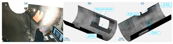
Figure 7.
Large-scale thermography inspection of the lower fuselage skin of the MFFD mapped to a 3D CAD model with (a) a picture of the LPT measurement; (b) a result of the RHS and (c) the LHS.
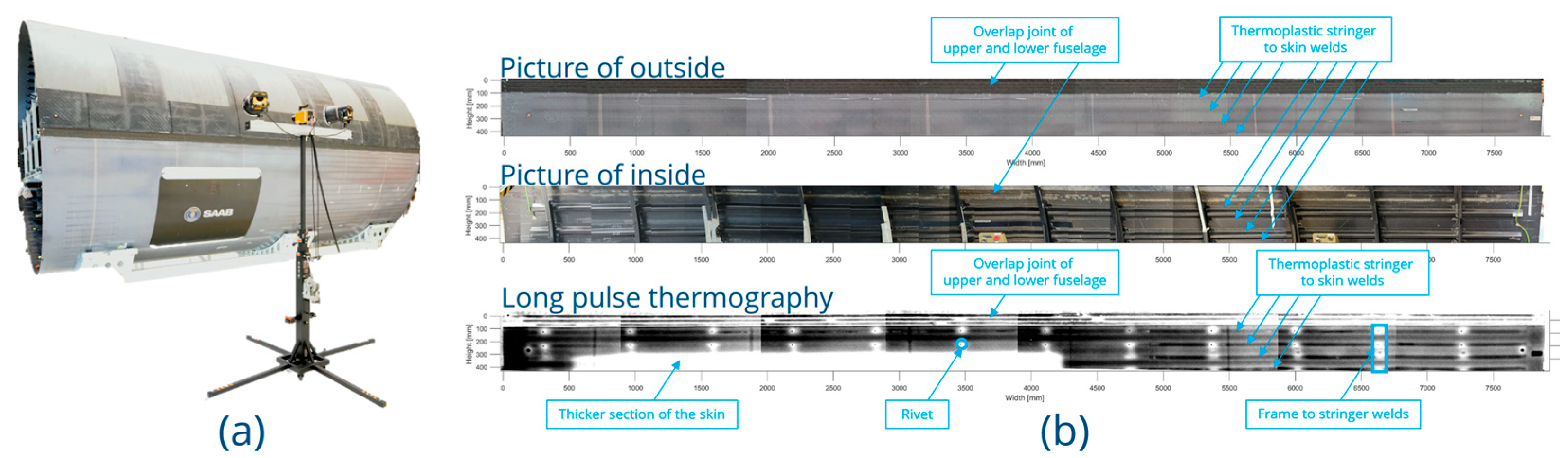
The second example, shown in Figure 8, is an outside LPT inspection of the 8 m long overlap joint and top two omega stringers on the RHS of the consolidated MFFD. Performing the inspection from the outside allows for the easy implementation of the inspection in the production line. This work is part of an ongoing study to investigate the potential of thermography for the inspection of TP welds. In this early phase, it is clear that in the thin fuselage skin, minor indications and engineered thickness variations can be detected. Additionally, certain weld features can be identified, including the location of stringer-to-skin welds, frame-to-stringer welds, and damage to the fuselage skin over these welds.
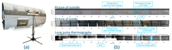
Figure 8.
Large-scale thermography inspection of the overlap joint on the RHS of the MFFD with (a) a picture of the set-up at Airbus ZAL, Hamburg, Germany, and (b) LPT inspection and corresponding pictures of the inside and outside.
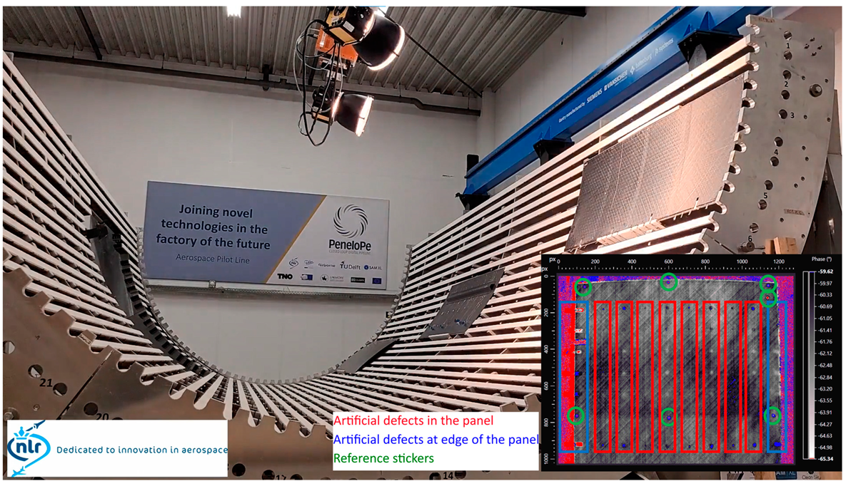
To realize the potentially high speed of inspection that IRT can offer in practice necessitates automation. An example of automating these inspections is shown in Figure 9, where the IRT set-up shown in Figure 7 and Figure 8 is integrated into a gantry running within a ROS2 environment at SAMXL, Delft. Three panels have been placed in the MFFD lower fuselage assembly jig to simulate the production of a full lower fuselage skin. The thermography inspection can be run automatically and directed to any location in the lower fuselage assembly jig. Annotated inspection results can then be returned to the digital pipeline of the simulated production line. Within such an integrated set-up, the LPT inspection of a 50 m2 lower fuselage part only requires 1.5 h, which is ~10 times faster than the 14.5 h required, should this same part be inspected in an ultrasound C-scan.
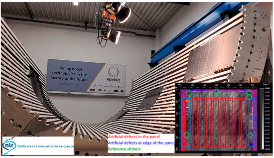
Figure 9.
Picture of an automated large−scale thermography inspection in the assembly jig of the lower fuselage of the MFFD at SAMXL, Delft, the Netherlands, with, in the lower right corner, an inserted OLT inspection result where artificial defects are highlighted in blue and red.
4. Conclusions
Using IRT, an NDT technique that requires no contact or couplant, an approach to attain a quick inspection of TP CFRP fuselage skin is demonstrated at a rate of 30 m2/h. It is, however, important to keep in mind the limitations of the technology. In this work, we have demonstrated the suitability of IRT for the detection of engineered thickness variations, inclusions, and delaminations in TP CFRP fuselage skin with panel thickness up to 2.0 mm and defect size down to ¼”. The porosity in the reference panel is missing. To assess thicker parts, a solution could be to scan the part from both the inside and the outside. Further research to determine the limits of the technology for other defect types in fuselage skin (porosity, voids, and BVIDs) and assessment of the quality of TP welds and multi-material parts is ongoing. In general, LPT leads to faster inspection times, while OLT can provide defect-depth information. The automation of IRT is straightforward, as the robot only needs to be programmed to hold position during the inspection, rather than following a complicated path, providing a means for fast, automated inspection of large, >50 m2, parts.
Author Contributions
Conceptualization, D.B.D., D.J.P. and H.P.J.; formal analysis, D.B.D. and H.P.J.; investigation, D.B.D., A.F.B., D.E.B., E.S.v.V., D.J.P. and H.P.J.; writing—original draft preparation, D.B.D.; writing—review and editing, D.B.D., D.J.P. and H.P.J. All authors have read and agreed to the published version of the manuscript.
Funding
This research was funded by the following European Union projects: Large Passenger Aircraft Clean Sky 2 Joint Undertaking project no. 945583, PENELOPE Horizon 2020 project no. 958303, and the FASTER H2 Clean Aviation Joint Undertaking project no. 101101978.
Institutional Review Board Statement
Not applicable.
Informed Consent Statement
Not applicable.
Data Availability Statement
Restrictions apply to the datasets, as they are part of an ongoing study. Requests to access datasets should be directed to patrick.jansen@nlr.nl. Access to datasets containing (part of) the MFFD will be subject to restrictions specific to its owners.
Conflicts of Interest
The authors declare no conflicts of interest. The funders had no role in the design of the study; in the collection, analyses, or interpretation of data; in the writing of the manuscript; or in the decision to publish the results.
References
- Jansen, H.P.; Platenkamp, D.J.; Bosch, A.F. Multi-domain contactless NDI approach: Data fusion of structural light scanning with thermography and shearography. In Proceedings of the ECNDT Conference, Lisbon, Portugal, 3–7 July 2023. [Google Scholar]
- Jansen, H.P.; Platenkamp, D.J.; Hwang, J. Hybrid Inspection Method using Three Dimensional Scanning, Lock-in Thermography and Laser Shearography. In Proceedings of the WCNDT Conference, Seoul, Republic of Korea, 27–31 May 2024. [Google Scholar] [CrossRef]
- Roth, Y.C.; Herrmann, R.; Sanchez Santos, C.; Uellendahl, M.; Koopman, J.; Henneberg, A.; Kos, J.; Villegas, I.F.; Choudhary, A.; Larsen, L.; et al. CleanSky2/Clean Aviation large passenger aircraft for more sustainable commercial fuselage technologies—Major achievements. In Proceedings of the ICAS Conference, Florence, Italy, 9–13 September 2024. Under Review. [Google Scholar]
- Poelman, G.; Hedayatrasa, S.; Segers, J.; Van Paepegem, W.; Kersemans, M. Efficient detection of production defects in a CFRP aircraft component by means of flash infrared thermography. In Proceedings of the SAMPE Europe Conference, Amsterdam, The Netherlands, 30 September–1 October 2020; Available online: http://hdl.handle.net/1854/LU-8678899 (accessed on 1 October 2024).
- Seresini, T.; Yuan, P.; Grüber, J.; Mayr, G.; Burgholzer, P.; Pecoriello, L.; Glorieux, C. Investigation of delamination in carbon fiber reinforced plastic by means of pulse thermography, shearography and active thermography. In Proceedings of the Meetings on Acoustics, Bruges, Belgium, 3–6 September 2019; Volume 38. [Google Scholar] [CrossRef]


Disclaimer/Publisher’s Note: The statements, opinions and data contained in all publications are solely those of the individual author(s) and contributor(s) and not of MDPI and/or the editor(s). MDPI and/or the editor(s) disclaim responsibility for any injury to people or property resulting from any ideas, methods, instructions or products referred to in the content. |
© 2025 by the authors. Licensee MDPI, Basel, Switzerland. This article is an open access article distributed under the terms and conditions of the Creative Commons Attribution (CC BY) license (https://creativecommons.org/licenses/by/4.0/).