Abstract
Hydrogen as fuel in civil aviation gas turbines is promising due to its no-carbon content and higher net specific energy. For an entry-level market and cost-saving strategy, it is advisable to consider reusing existing engine components whenever possible and retrofitting existing engines with hydrogen. Feasible strategies of retrofitting state-of-the-art Jet A-1 fuelled turbofan engines with hydrogen while applying minimum changes to hardware are considered in the present study. The findings demonstrate that hydrogen retrofitted engines can deliver advantages in terms of core temperature levels and efficiency. However, the engine operability assessment showed that retrofitting with minimum changes leads to a ~5% increase in the HP spool rotational speed for the same thrust at take-off, which poses an issue in terms of certification for the HP spool rotational speed overspeed margin.
1. Introduction
In recent years, the aviation industry has experienced significant growth, leading to a rapid increase in emissions from air transportation. The aviation sector is responsible for 2–3% of all anthropogenic carbon emissions and 12% of transport-related emissions. Reducing the climate impact further represents one of Europe’s principal objectives. Commercial aircraft manufacturers have concentrated on enhancing fuel efficiency to lower operational expenses and boost the payload capacity for airline operators. The aviation industry accounts for 2.5% of worldwide CO2 emissions, resulting in a 4% increase in global warming, as illustrated in Figure 1 [1,2].
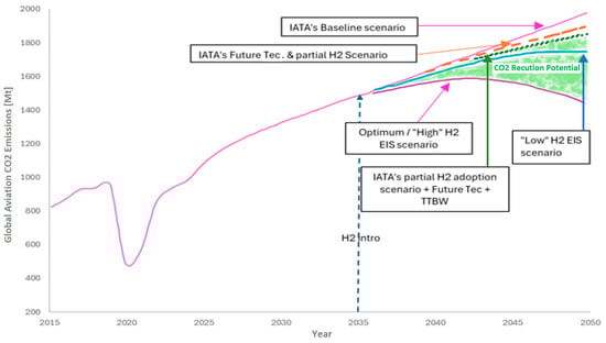
Figure 1.
CO2 reduction potential vs. time. Graph from IATA’s technology assumptions (Aircraft Technology Net Zero Roadmap, IATA 2023) annotated by the authors of [2].
Alternative aviation fuels encompass bio-jet fuels (kerosene-type fuels derived from biomass), synthetic jet fuels (kerosene-type fuels synthesized from natural gas and coal), liquefied natural gas (LNG), liquefied hydrogen (LH2), and electricity. The utilization of hydrogen (H2) as an alternative aviation fuel represents a significant advancement in the development of future aircraft engines, aimed at reducing emissions [3,4,5]. H2 is easily accessible, possesses the highest energy density (120 MJ/kg) when compared to other chemical fuels, and offers 2.5 times the energy density per unit mass of hydrocarbon fuels. It presents significant opportunities for core operating temperature reduction, as well as energy/fuel efficiency [6,7,8].
The ICAO Committee on Aviation Environmental Protection has predicted that carbon dioxide emissions will rise by 21%, while nitrogen oxide emissions are expected to increase by 16% [4]. Many studies have been conducted in recent years (e.g., [9,10,11,12,13,14]) identifying H2 as a crucial step for achieving green aviation and bridging the decarbonization gap in the aviation sector. Some of them include studies on the introduction of first-generation H2 planes, including considerations of retrofitting existing equipment in potential near-future scenarios [11,12,13,14]. Such studies were the inspiration to delve deeper into the performance of H2-fuelled aircraft engines derived by retrofitting existing kerosene ones.
2. Methodology
When considering retrofitting conventional aero gas turbines with H2 fuel, certain modifications must be considered. Initially, the fuel system needs to be completely different. Then, the combustion chamber must be redesigned to prevent extremely high H2 flame temperatures and must be mixed with air and H2 effectively, taking advantage of its lean combustion abilities. These modifications are necessary to ensure the feasibility of incorporating H2 fuel. Beyond these, modifications to the hot section gas path can also be envisaged in an effort to adapt the engine design to the different gas composition.
In the present study, three strategies for engine modification are considered. The engine cycle design and performance simulations were performed using Turbomatch 3.0 software [15,16]. The engine modification strategies considered herein are as follows.
2.1. Baseline Kerosene Engine (BKE)
The baseline engine model is inspired by a state-of-the-art three-shaft turbofan engine, configured with a single-stage fan, 8-stage IPC, 6-stage HPC, single-stage HPT, 2-stage IPT, and 6-stage LPT. The engine cycle design is set utilizing a standard three-point cycle design matching scheme. The thrust requirements for the three points of the cycle design, mid-cruise (MCR), top of climb (TOC), and end of runway (EOR), are presented in Table 1. These are assumed based on typical thrust ratios for such applications.

Table 1.
Net thrust requirements for baseline kerosene engine.
The efficiencies for the turbomachinery components as well as the cycle design core temperature constraints are detailed in Table 2. These refer to an Entry-Into-Service 2025–2035 timeframe. The optimum fan pressure ratio (FPRopt) is achieved at cruise by iterating to minimize specific fuel consumption (SFC), as suggested by Guha [17]. The fan diameter is maintained at 3 m, a fact which largely determines the TOC mass flow rate.
Table 2.
Component efficiencies and cycle design core temperature constraints for EIS 2025–2035.
Following the modelling of the BKE, the next step involved modelling the H2 fuel system needed for the retrofit strategies. The combustor is assumed to operate effectively with H2 fuel at both lean and full load conditions. The H2 fuel is introduced into the combustion chamber as a gas at 250 K, assumed to be vaporized by a heat exchanger, while it is stored in the aircraft tanks as a liquid (cryogenic tanks at approximately 20 K [18]). The goal was to utilize the BKE as modelling platform and adapt it to operate on H2 fuel while maintaining a high degree of component commonality. This approach would enable a performance comparison of the H2 retrofitted engines with the BKE.
2.2. Strategy 1: New Hot Section H2 (HS-H2)
The first proposed strategy suggests replacing the fuel system and combustor, while redesigning the hot section to accommodate changes due to the gas properties of hydrogen combustion products. All cold section components remained the same with the BKE (this means that the same component characteristics were). In this case, the turbine components and the core nozzle require modifications, ranging from partial changes to a complete redesign of the components. This methodology ensured that the cold end components remained the same with the BKE, while the combustion chamber and hot end components were retrofitted for H2 fuel. This approach allowed for the evaluation of the performance of the H2 retrofitted engine to meet thrust requirements during the three cycle design points. This study also aimed to determine whether this retrofit strategy would be practical for engine operation. Due to H2’s higher energy density, the core nozzle area was readjusted and reduced by 12.1% compared to the BKE.
2.3. Strategy 2: New Combustor and Nozzle H2 (CN-H2)
The second potential strategy for retrofitting H2 fuel is only to replace the fuel system and the combustor while adjusting the core nozzle area. In this case, all compressors and turbines remain the same as in the BKE. The core nozzle area was reduced by 12.13% relative to the BKE to accommodate the changes due to the gas properties of the exhaust gases.
2.4. Strategy 3: New Combustor H2 (C-H2)
The final potential retrofitting strategy considered the minimum number of changes to engine hardware. Thus, only the fuel system and the combustion chamber were replaced, while all other engine components, including the core nozzle, remained the same as in the BKE.
3. Results and Discussion
3.1. Engine Performance (MCR Conditions)
The BKE is designed to operate efficiently at the MCR point for turbofan engines, as most of the fuel is consumed during this stage. Thus, this was the operating point selected as the cycle design point. The design point performance parameters for the BKE are detailed in Table 3.
Table 3.
MCR performance data for BKE.
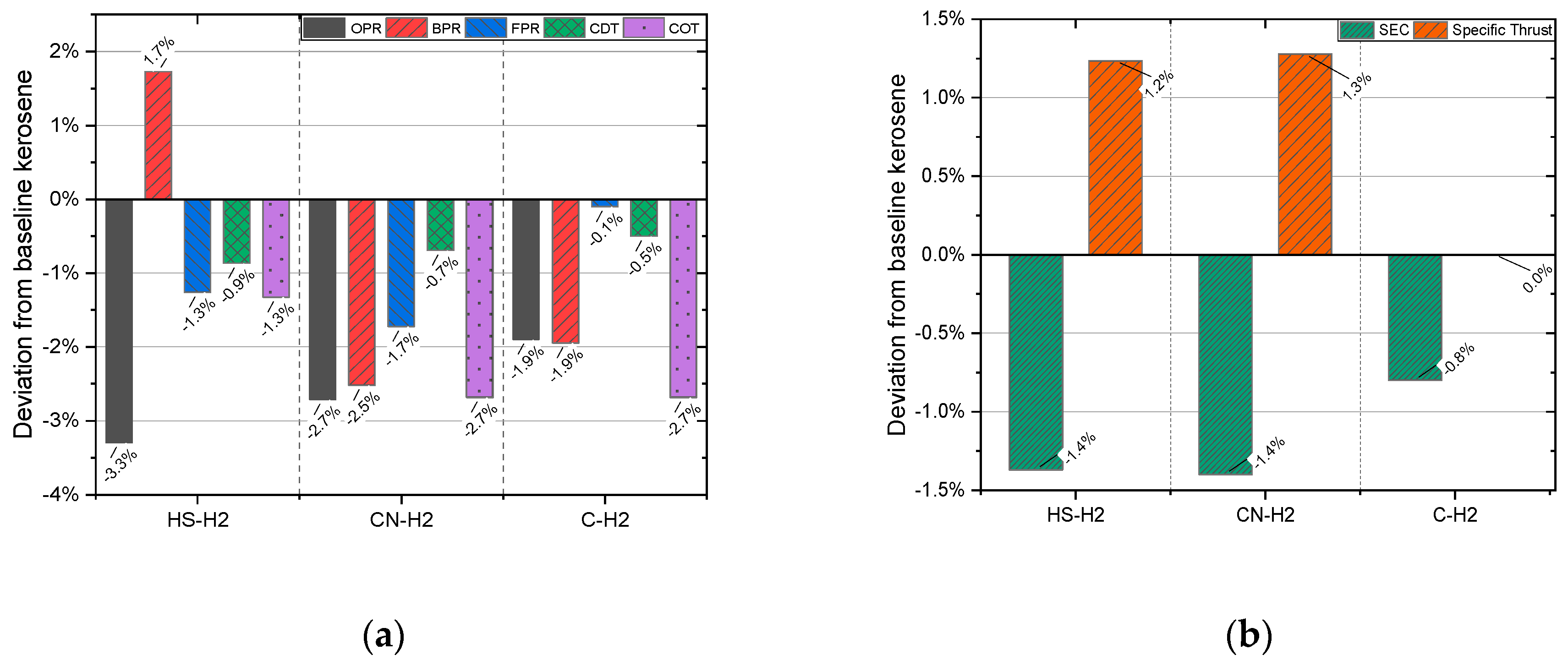
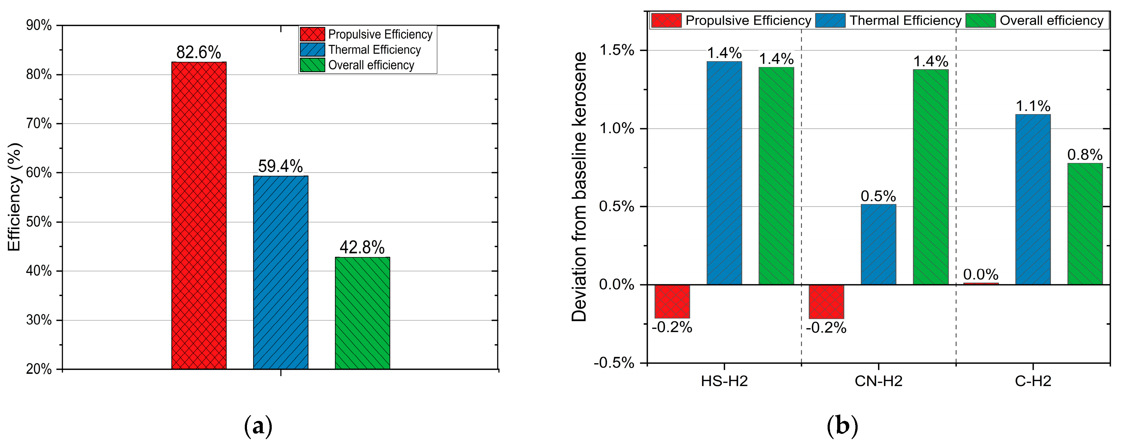
All H2 retrofitted engines are designed to match the exact thrust output of the BKE. Figure 2a below demonstrates that all three retrofitted engines at MCR operate at a lower overall pressure ratio (OPR) compared to the BKE, with reductions of 3.3%, 2.7%, and 1.9%, respectively. This is accompanied by reductions in the fan pressure ratio (FPR) and compressor delivery temperature (CDT). This is due to the amount and composition of the new combustion gases that forced the spools to balance at lower levels of rotational speed for the same thrust. Notably, the HS-H2 engine exhibits a higher bypass ratio (BPR) of 1.7%, while the CN-H2 and C-H2 engines display lower BPRs of 2.5% and 1.9%, respectively, compared to the BKE. This shows the redistribution of the flows due to the adjustment of the engine spool rotation to the new equilibrium operating conditions (generally referred to as the “rematching” of spools). The rematching of spools involves balancing high-, low-, and intermediate-pressure spools while they operate at different rotational speeds to drive the compressor and turbine stages, which require careful coordination for efficiency. After upgrading components like advanced turbine blades, spool rematching ensures smooth power transfer and optimized airflow. Based on this, the combustor outlet temperatures (COTs) for all three retrofitted engines were found to be lower than those of the BKE by 1.3%, 2.7%, and 2.7%, respectively. Figure 2b shows that at the same MCR thrust, the HS-H2, CN-H2, and C-H2 variants have a 1.4%, 1.4%, and 0.8% reduction in specific energy consumption (SEC), respectively, increasing the overall engine efficiency (see Figure 3b). Both HS-H2 and CN-H2 engines exhibit higher specific thrust, which results in lower propulsive efficiency; however, for the C-H2 engine, specific thrust remains the same as that for the BKE.
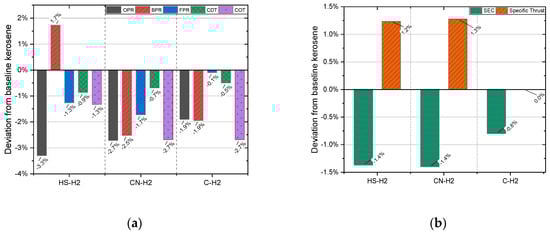
Figure 2.
Parameters of H2 retrofitted engines compared to BKE under MCR condition: (a) OPR, BPR, FPR, CDT, and COT; (b) SEC and specific thrust.

Figure 3.
Parameters of H2 retrofitted engines compared to BKE under MCR condition: (a) Efficiencies of BKE; (b) Deviation of efficiencies from BKE.
3.2. Engine Performance (TOC and EOR Conditions)
All three H2 retrofitted engines are simulated to run at the same thrust requirements with the BKE. Table 4 shows the main parameters for the BKE.
Table 4.
TOC and EOR performance data for BKE.
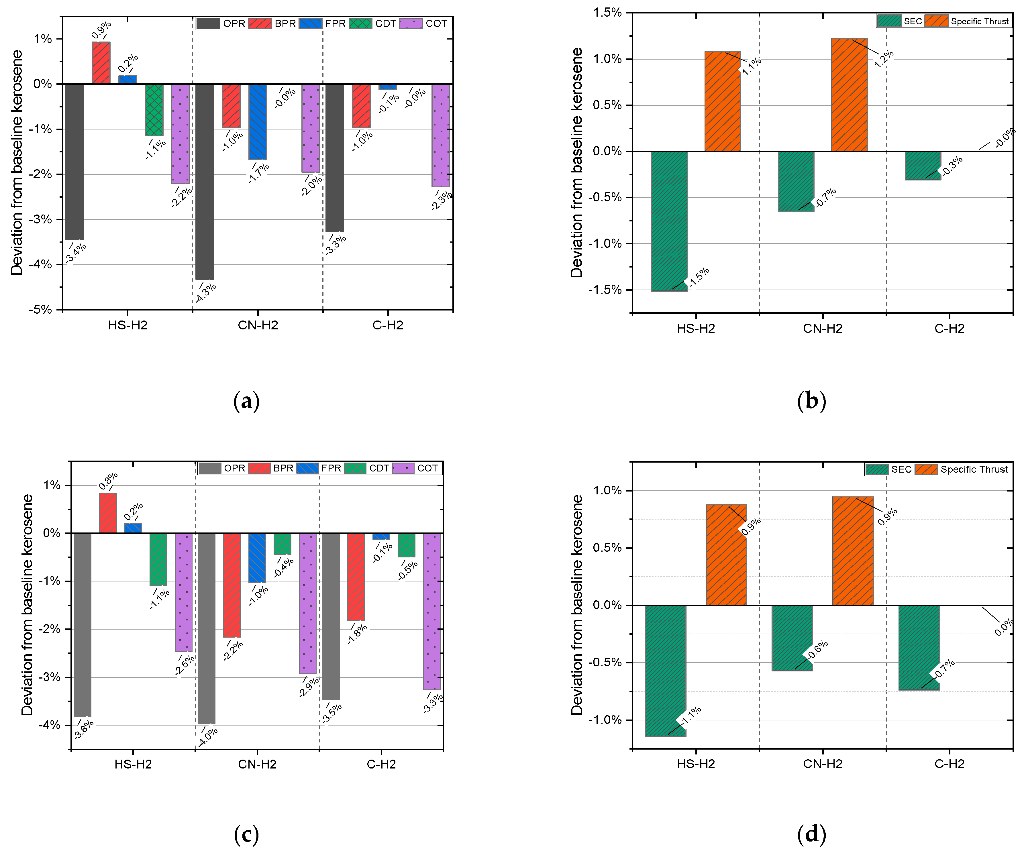
All retrofitted engines operate at lower OPR and COT values, as shown in Figure 4. This indicates that all three retrofitted engines operate below the blade temperature technology threshold under the EOR conditions for both the compressor outlet and turbine inlet. This can enhance the engine’s lifespan and reduce maintenance frequency. Furthermore, lower core temperatures can lead to lower NOx emission characteristics for such engines. Nonetheless, despite the fact that the H2 retrofitted engine variants show lower levels of OPR and core temperatures in general, they still provide lower specific energy consumption at all points presented herein.

Figure 4.
Parameters of H2 retrofitted engines compared to BKE: (a) OPR, BPR, FPR, CDT, and COT under TOC condition; (b) SEC and specific thrust under TOC condition; (c) OPR, BPR, FPR, CDT, and COT under EOR condition; (d) SEC and specific thrust under EOR condition.
3.3. Engine Operability
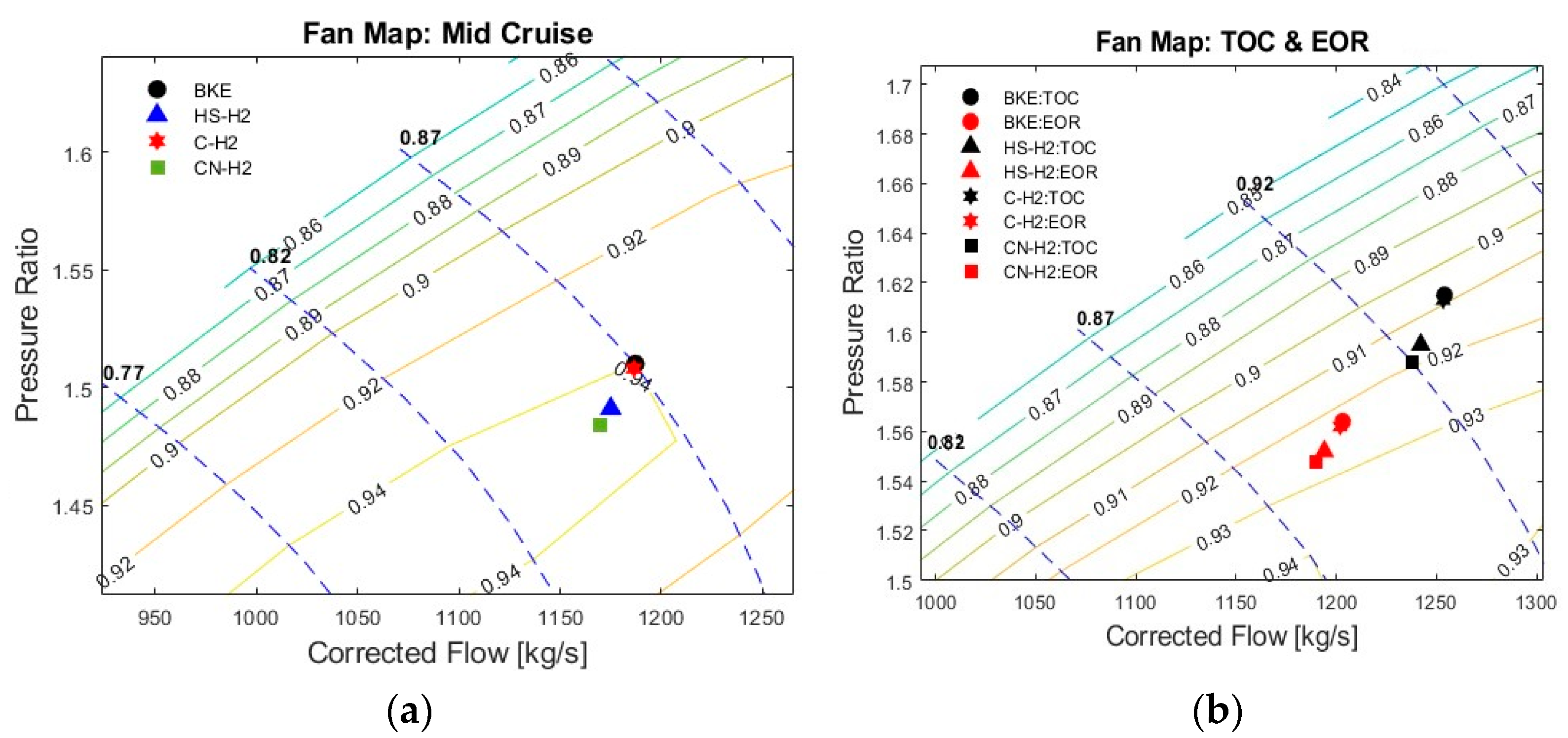
Engine operability is evaluated from an off-design, steady-state performance point of view. This study refers to assessing the compressor surge margins and the rotational speed levels of both spools. This is performed to ensure that the H2 retrofitted variants do not cross the limit values of acceptance. Figure 5a illustrates the fan characteristics with the MCR points of all engine models, while Figure 5b shows the same characteristics but with the TOC and EOR points. The MCR points of the HS-H2 and CN-H2 engines are at a lower FPR, and corrected flow compared to the BKE. This is due to the spools rematching at lower rotational speed levels for the same thrust, as discussed previously. The C-H2 engine’s operating point remains close to the BKE, showing no significant changes. This is due to the fact that all component characteristics remained unchanged (fixed hardware), and the presence of H2 fuel changed the HP spool balance while the LP spool remained unaffected, leading to the same level of specific thrust as the that of the BKE. Similar trends are observed for all H2 retrofitted engines at the two off-design points. This illustrates that as far as the fan is concerned, none of the H2 retrofitted variants present any behaviour that would lead to surge or overspeed.
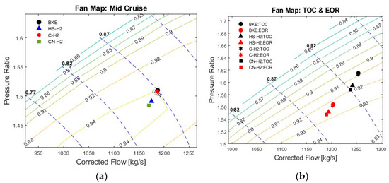
Figure 5.
Fan map operating points for BKE and H2 retrofitted variants at (a) MCR and (b) TOC and EOR.
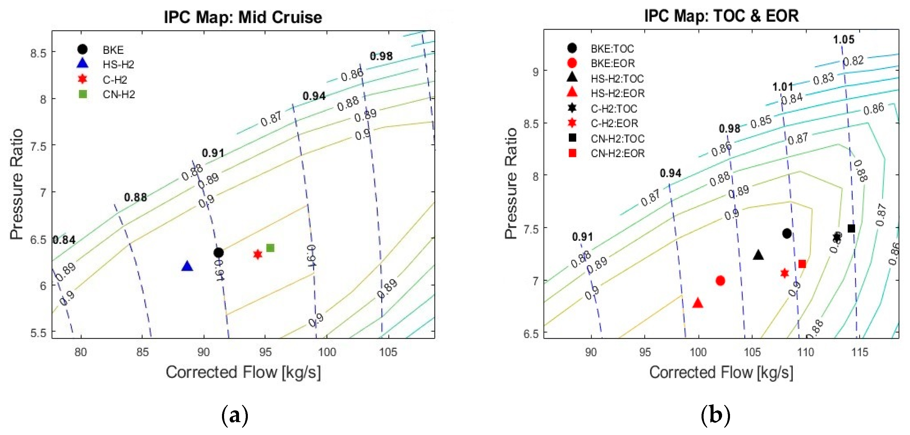
Figure 6a,b illustrate the MCR, TOC and EOR operating points for all engines in the IP compressor characteristics. In this case, the IP spool rotational speed increases for both CN-H2 and C-H2 engines by 2% and 1.5%, respectively. Conversely, the IP spool rotational speed of the HS-H2 engine decreases by 2.2%. Under the TOC and EOR conditions, the IP spool rotational speed of the HS-H2 engine decreases by 1.5%, while for both C-H2 and CN-H2 engines, it increases by 3% and 4%, respectively. These show that some consideration has to be included regarding the increased IP spool rotational speed, although the levels of increase do not seem to reach any limiting values. Regarding the IP compressor surge margin, it either remains practically constant (the HS-H2 variant) or it actually increases (the CN-H2 and C-H2 variants) compared to the BKE. Thus, IP spool operability seems to result in acceptable levels for all H2 retrofitted variants.
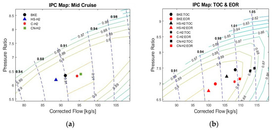
Figure 6.
IPC map operating points for BKE and H2 retrofitted variants at (a) MCR and (b) TOC and EOR.
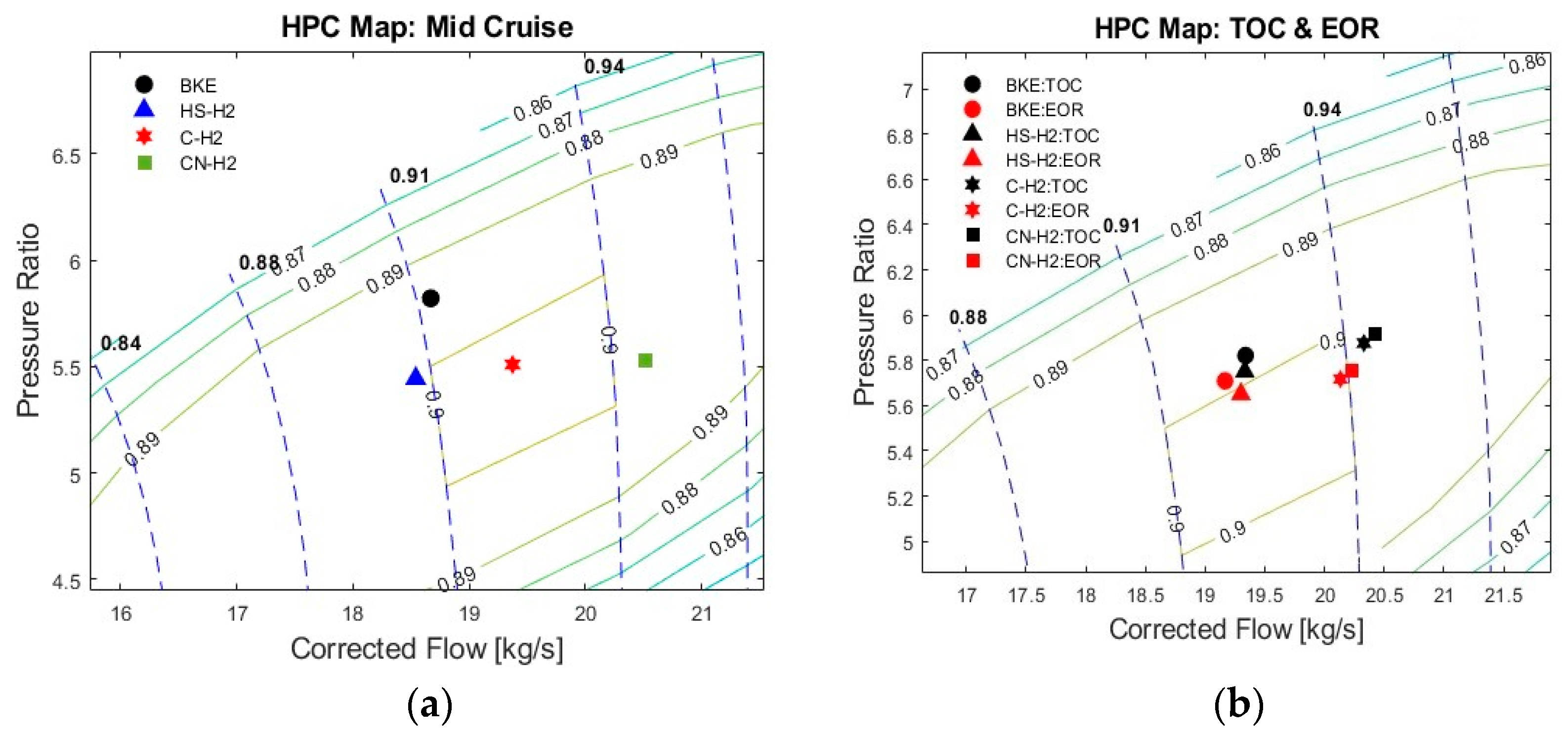
Finally, Figure 7a,b illustrate the MCR, TOC and EOR operating points for all engines in the HP compressor characteristics. At Mid-Cruise (MCR), all H2 retrofitted variants rematch at a lower pressure ratio level; thus, a higher surge margin is obtained compared to the BKE. However, although the HS-H2 variant showed similar HP spool rotational speed levels to the BKE, the CN-H2 and C-H2 variants exhibited higher rotational speeds by 3.5% and 1.5%, respectively. Such a speed increment can be within acceptable overspeed limits for such engines. However, under TOC and EOR conditions, the HP spool rotational speed increments for the CN-H2 and C-H2 variants were 5.5% and 5%, respectively. From a certification point of view, such values can be considered as borderline for an acceptable HP spool overspeed margin, keeping in mind that further overspeed margins will still need to be considered for the H2 retrofitted variants.
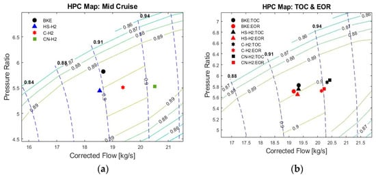
Figure 7.
HPC map operating points for BKE and H2 retrofitted variants at (a) MCR and (b) TOC and EOR.
4. Conclusions
The present work highlights the key performance and operability attributes of existing engines retrofitted to run on H2 gas. The study excluded any H2 fuel conditioning from the calculations. All H2 retrofitted engines show potential for a reduction in both SEC and core temperatures. Even for the case of only modifying the fuel system and the combustor, the engine cycle performance shows potential for reduced core temperatures, with all the benefits that come with it, without compromising SEC. However, it is important to note that the engine operability assessment showed that care needs to be taken with the HP spool rotational speed adjustment and its overspeed margin. Besides that, the surge margins of all compressors, for all H2 retrofitted variants, were found to be acceptable. The next steps of this work involve “H2 Clean Sheet” engine design strategies for the same application and a final evaluation and comparison of all H2 variants against the BKE.
Author Contributions
Conceptualization, resources, methodology, software, validation, J.F. and C.M.; formal analysis, investigation, data curation, J.F.; writing—original draft preparation, J.F.; writing—review and editing, J.F. and C.M.; visualization, J.F.; supervision, C.M. and P.P.; project administration, P.P. All authors have read and agreed to the published version of the manuscript.
Funding
This research received no external funding.
Institutional Review Board Statement
Not applicable.
Informed Consent Statement
Not applicable.
Data Availability Statement
Data are contained within the article.
Conflicts of Interest
The authors declare no conflicts of interest.
References
- Hannah, R. Global Inequalities in CO₂ Emissions from Aviation; Our World in Data: Oxford, UK, 2020. [Google Scholar]
- Pantelis, I.; Block, A.; Nikolaidis, T.; Pilidis, P. A Market Introduction of Hydrogen Propulsion for First Generation Civil Airliners. In Proceedings of the 2024 ISABE Conference, Toulouse, France, 22–27 September 2024. ISABE Paper 2024-197. [Google Scholar]
- Balli, O.; Sohret, Y.; Karakoc, H.T. The Effects of Hydrogen Fuel Usage on the Exergetic Performance of a Turbojet Engine. Int. J. Hydrogen Energy 2018, 43, 10848–10858. [Google Scholar] [CrossRef]
- Najjar, Y.S.H.; Zahed, A.H.; Bashir, M.D.; Alp, T. Feasibility of Hydrogen Utilization in Gas Turbine Engines. Energy Environ. 1990, 1, 240–251. [Google Scholar] [CrossRef]
- Mourouzidis, C.; Singh, G.; Sun, X.; Huete, J.; Nalianda, D.; Nikolaidis, T.; Sethi, V.; Rolt, A.; Goodger, E.; Pilidis, P. Abating CO2 and non-CO2 emissions with hydrogen propulsion. Aeronaut. J. 2024, 128, 1576–1593. [Google Scholar] [CrossRef]
- Hughes, C. Realising Zero-Carbon Emission Commercial Flight Our Vision for Zero-Carbon Emission Air Travel; Flyzero, Ati, FZO-ALL-REP-0004; Flyzero: London, UK, 2022. [Google Scholar]
- Sasi, S.; Mourouzidis, C.; Roumeliotis, I.; Nikolaidis, T.; Pachidis, V.; Normal, J. Impacts of alternative aviation fuels on engine cycle design and aircraft mission capability. In Proceedings of the ASME Turbo Expo 2023, Boston, MA, USA, 26–30 June 2023. [Google Scholar]
- Fly Zero Reports; Aerospace Technology Institute, University Way: Cranfield, UK, 2022; Available online: https://www.ati.org.uk/flyzero-reports/ (accessed on 1 October 2024).
- ENABLing Cryogenic Hydrogen Based CO2 Free Air Transport (ENABLEH2), CORDIS Project Portal. Available online: https://cordis.europa.eu/project/id/769241 (accessed on 21 September 2024).
- Plans Unveiled for “World’s First” Hydrogen-Electric WIGE Vessel—Offshore Energy. Available online: https://www.offshore-energy.biz/plans-unveiled-for-worlds-first-hydrogen-electric-wige-vessel/ (accessed on 19 September 2024).
- Huete, J.; Nalianda, D.; Pilidis, P. Propulsion System Integration for a first generation civil airliner? Aeronaut. J. 2021, 125, 1654–1661. [Google Scholar] [CrossRef]
- Huete, J.; Nalianda, D.; Pilidis, P. Impact of tank gravimetric efficiency on Propulsion System Integration for a first generation civil airliner? Aeronaut. J. 2022, 126, 1324–1332. [Google Scholar] [CrossRef]
- Huete, J.; Pilidis, P. Parametric study on tank integration for hydrogen civil aviation propulsion. Int. J. Hydrogen Energy 2021, 46, 37049–37062. [Google Scholar] [CrossRef]
- Pantelis, I.; Huete, J.; Nalianda, D.; Jarzebowska, E.; Pilidis, P. Hydrogen propulsion for civil aviation: An introduction scenario. In Proceedings of the 2022 ISABE Conference, Ottawa, ON, Canada, 25–30 September 2022. ISABE Paper 2022-313. [Google Scholar]
- Nikolaidis, T. TURBOMATCH–Gas Turbine Performance Simulation–User Manual; Cranfield University: Cranfield, UK, 2017; Unpublished. [Google Scholar]
- MacMillan, W.L. Development of a Modular-Type Computer Program for the Calculation of Gas Turbine Off-Design Performance; Cranfield University: Bedford, UK, 1974. [Google Scholar]
- Guha, A. Optimisation of Aero Gas Turbine Engines. Aeronaut. J. 2001, 105, 345–358. [Google Scholar] [CrossRef]
- Jackson, A.J.B. Optimisation of Aero and Industrial Gas Turbine Design for the Environment; Cranfield University: Cranfield, UK, 2009. [Google Scholar]

Disclaimer/Publisher’s Note: The statements, opinions and data contained in all publications are solely those of the individual author(s) and contributor(s) and not of MDPI and/or the editor(s). MDPI and/or the editor(s) disclaim responsibility for any injury to people or property resulting from any ideas, methods, instructions or products referred to in the content. |
© 2025 by the authors. Licensee MDPI, Basel, Switzerland. This article is an open access article distributed under the terms and conditions of the Creative Commons Attribution (CC BY) license (https://creativecommons.org/licenses/by/4.0/).