Proceeding Paper

An Analytical Model for the Prediction of the Stiffness Behavior of Thin-Walled Beams †

by
Hugo Miguel Silva
1,* and
Jerzy Wojewoda
2
1
Independent Researcher, 4815-394 Vizela, Portugal
2
Division of Dynamics, Lodz University of Technology, Stefanowskiego 1/15, 90-924 Lodz, Poland
*
Author to whom correspondence should be addressed.
Presented at the 5th International Electronic Conference on Applied Sciences, 4–6 December 2024; Available online: https://sciforum.net/event/ASEC2024.
Eng. Proc. 2025, 87(1), 15; https://doi.org/10.3390/engproc2025087015
Published: 11 March 2025
(This article belongs to the Proceedings of The 5th International Electronic Conference on Applied Sciences)

Abstract

The aim of this work is to develop and test an analytical model that is deemed to be more accurate than the traditional method in the prediction of the mechanical behavior of hollow box beams. The methodology was tested with a hollow box beam of a rectangular section. To achieve the aim, a new analytical model was derived. An FEM model of a simple box beam was built, and the results of the comparison between the classical theory, the novel equation, and the l numerical method are presented. It was possible to validate the new equation with the numerical model and the classical equation. It was observed that the novel equation can predict the mechanical behavior of the studied geometries with better accuracy than the classical equation.

1. Introduction

The mechanical behavior of engineering structures is a fundamental aspect of every structural application. The improvement in the movement capability due to lightness and stiffness in devices with mobile parts, such as laser cutting machines and plotter applications, is an important industrial aspect [1,2]. The present paper aims to present a model that can predict the mechanical behavior of thin-walled beams. Regarding the specific focus of this paper, only a few works have been found in the literature [3,4,5]. Abambres et al. developed a geometrically and materially non-linear Generalized Beam Theory (GBT) formulation with the aim of analyzing the behavior and collapse of thin-walled members made of materials with a highly non-linear stress–strain curve such as stainless steel or aluminum [3]. Ayhan et al. studied the bending characteristics of thin-walled tubular beams with fixed supports for different beam lengths and diameters [4]. Lu and Yu studied the bending of rectangular and square tubes and thin-walled members of channel and angle sections [5]. Particular application aspects, including examples of analysis of profiles with either a single- or multiple-cell section for beams and blades, were shown by Jung et al. [6]. Their results include the influence of the thickness of the shell wall and account for the nonuniform distribution of shear strains across the section in the prediction of behavior under bending–torsion and extension–torsion coupling. Another extensive discussion of the bent tubular thin-walled parts, together with experiments and analytical analysis, is presented by Li et al. [7]. The paper by D’Aniello et al. [8] describes an analytical study aimed at developing a new explicit formulation for predicting the flexural overstrength factor of steel circular hollow section beams. The proposed models were derived from soft-computing techniques based on both neural networks (NNs) and gene expression programming (GEP), respectively. An interesting use of beam–column connection together with FE analysis in an existing facility is shown by Dhanapal et al. [9]. Fu et al. discussed that arched and straight beams under bending beams with square sections generally show much better energy absorption efficiency than those with circular sections [10]. The rationale for developing this improved analytical model stems from the limitations of classical beam equations in accurately predicting the mechanical behavior of thin-walled beams, particularly under transverse loading, especially for beams of complex geometries. Traditional methods often neglect the effects of shear deformation, leading to discrepancies between analytical and numerical results. By incorporating these effects, the new model provides a more precise representation of beam deflection and stiffness characteristics. In the case of a simple thin-walled beam, as studied in this work, the classical equation can predict stiffness behavior with good accuracy, but the derived equation is, on average, considering nine points, more accurate.

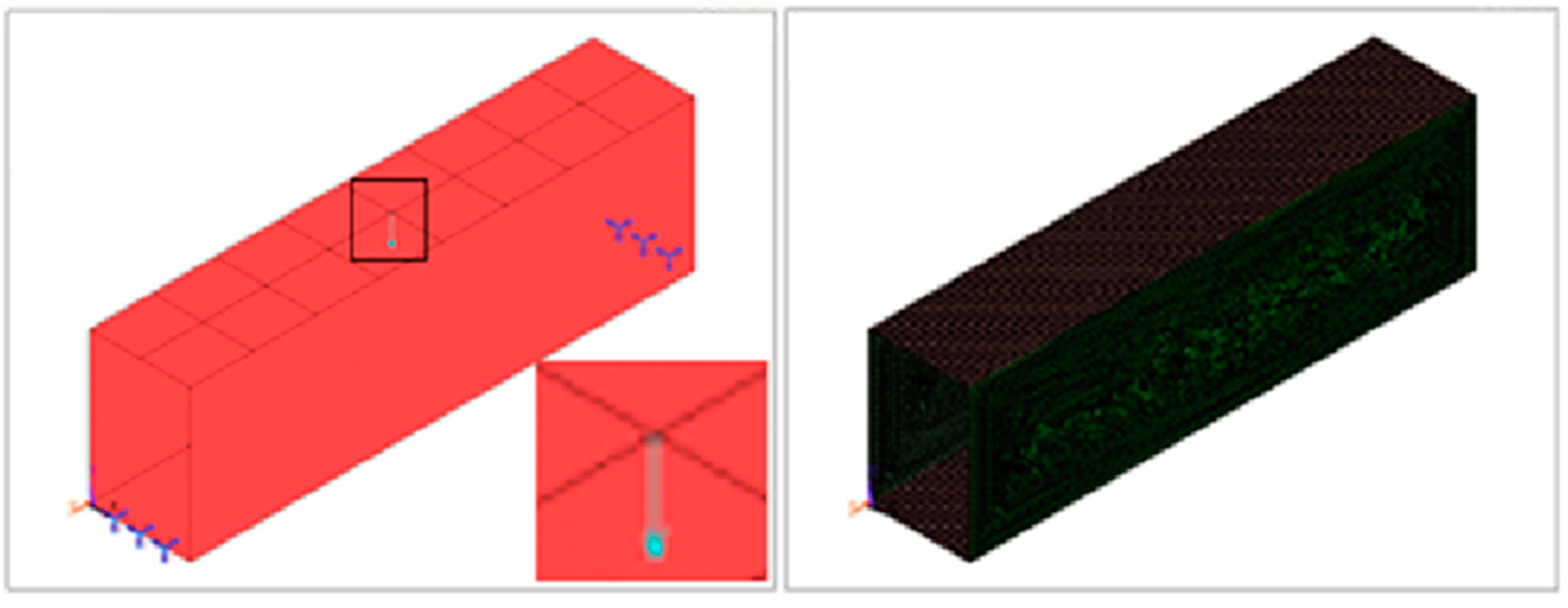
2. Numerical Procedure

A concentrated load P = 1500 N was applied, as shown in Figure 1 (left). Figure 1 (right) shows the mesh of the FEM model.
The mesh is a quadrilateral free mesh with a mean element size of 0.0025 m. The element type is Shell63. The boundary conditions were applied to two lines, one on each side, as shown in Figure 1 (left). The type of support is, therefore, simply supported at its ends. The used material’s properties were Young’s Modulus E = 210 × 109 Pa, Poisson coefficient of 0.29, and density of 7890 kg/m3 The results were measured at midspan, starting at z = 0 m, with increments of 0.125 m, for a total of 7 key points.

3. Analytical Procedures
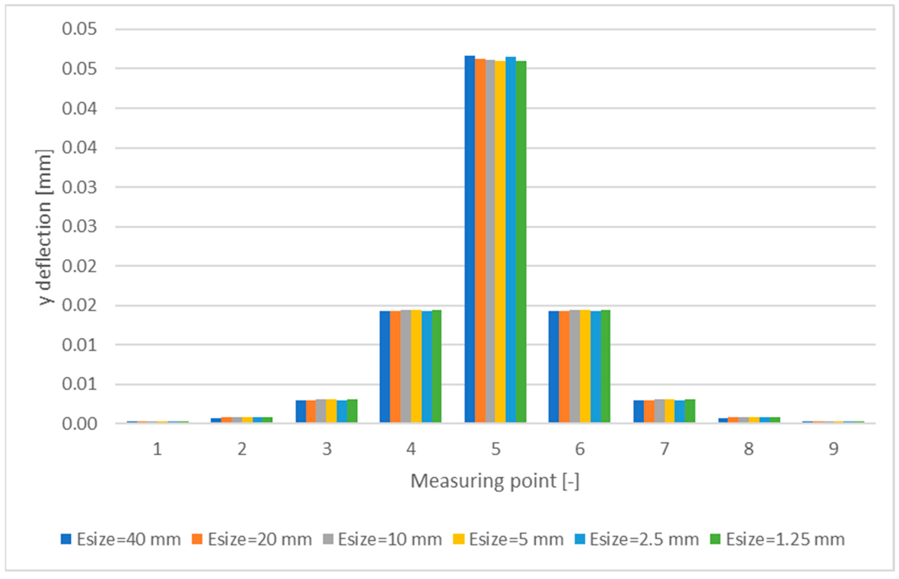
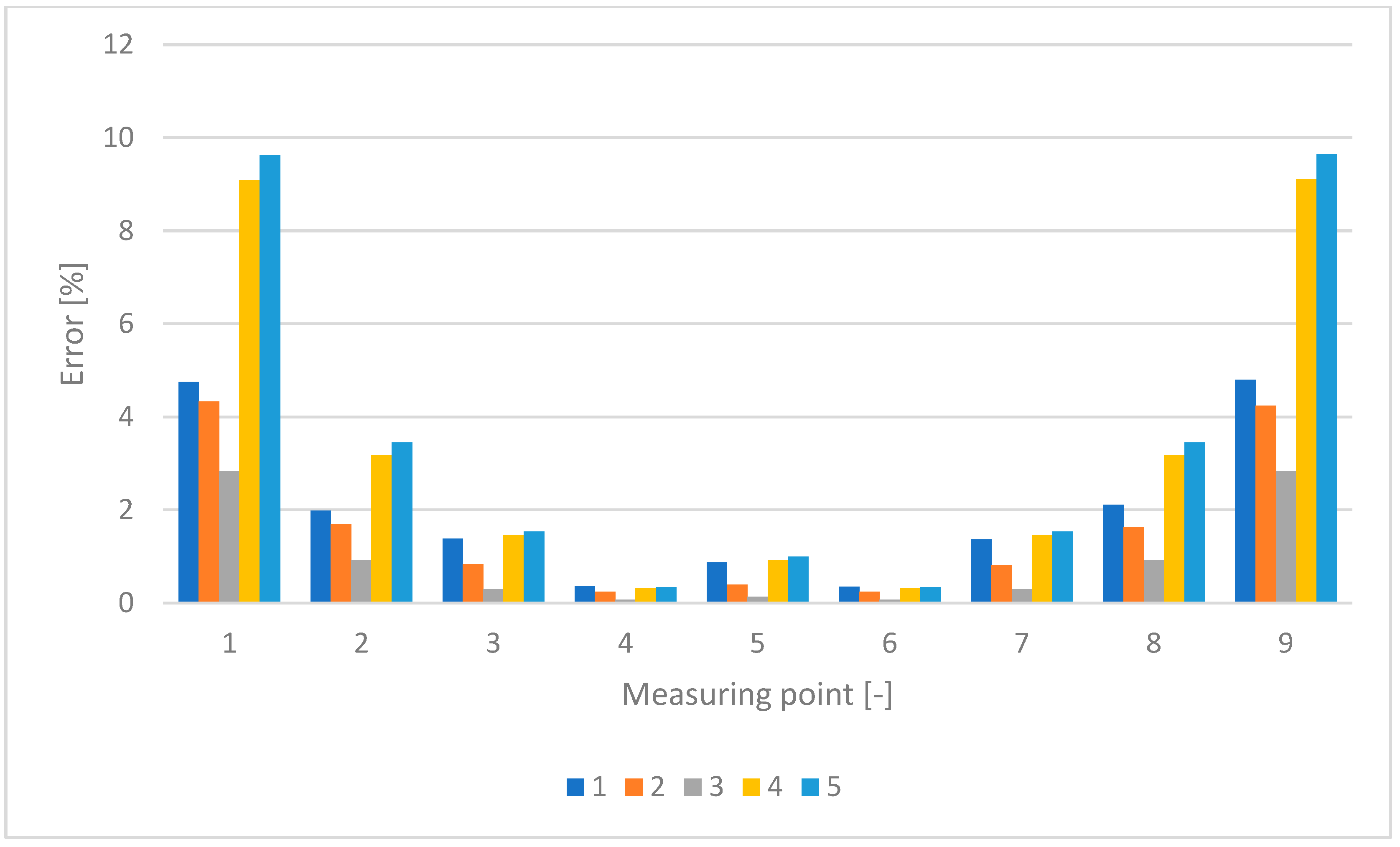
An equation was derived with the equation presented in [11] as the starting point. The deflection due to transverse loadings can be predicted as follows:
d 2 y d x 2 = 1 E I y y M f + β E I y y A G w
w can be replaced by its differential:
d y d x = 1 E I y y M f + β E I y y A G d T d x
The derivate of y can be found by integrating the expression into x. Hence:
d y d x = 1 E I y y P x 2 8 + β E I y y T A G   +   C 1  
The deflection y can also be found by integrating the expression into x.
y = 1 E I y y P x 2 8 + β E I y y T A G + C 1   dx
Resulting in the following:
y = 1 E I y y P x 3 24 + β E I y y T 2 A G x + C 1 x + C 2
The constants can be determined by using boundary conditions, by using X = 0 and y = 0; Considering C2 = 0 and using X = L; y = 0 results in the following:
C 1 x = 1 E I y y P x 3 24 + β E I y y T x 2 A G
Isolating C1, Equation (6) becomes
C 1 = 1 x E I y y P x 3 24 + β E I y y T x 2 A G
Substituting C1 and C2 for their corresponding expressions results in the following:
y = 1 E I y y P x 3 24 + β E I y y T x 2 A G + 1 E I y y P x 3 24 + β E I y y T x 2 A G
Simplification leads us to the final equation represented below:
y = 1 E I y y P x 3 12 + β E I y y T x A G  
where P is the applied load, Iyy is the Inertia Moment, X is the considered point, located at the midspan of the beam, along its longitudinal axis, B is a constant, which is equal to 3/2 for hollow-rectangular sections, A is the area, and G is the Transversal Elasticity modulus.
The derived Equation (9) includes shear deformation effects by incorporating the shear modulus G and the cross-sectional area A. This is similar to Timoshenko beam theory, represented by Equation (10), which improves upon the Euler–Bernoulli theory by considering shear flexibility through a correction factor k [11].
y ( x ) = P 6 E I ( 3 L x 2 x 3 ) + P k G A ( L x ) .
Timoshenko’s equation separates deflection into bending and shear components. The bending term follows classical beam theory, while the shear term accounts for transverse deformation. While both models include shear deformation, the derived equation expresses it differently.
The classical equation was taken from [12] and is shown below: (Equations (11) and (12))
y = 1 E I y y P b x 6 l l 2 b 2 x 2   for   x a
y = 1 E I y y P b x 6 l l 2 b 2 x 2 + P ( x a ) 3 6   for   x a
where b and a are the distances of load application in relation to the supports. In this work, a = b = L/2.

4. Results

A mesh sensitivity analysis was performed to select the element size that yields the most accurate results for the numerical model. Element sizes of 40, 20, 10, 5, 2.5, and 1.25 mm were studied. The y-deflection results are shown in Figure 2.
The results in Figure 3 were analyzed by means of Equation (13):
e r r o r ( % ) = δ y x δ y x 1 δ y x 100
where δyx is the deflections by the model with the highest element size of the comparison and δyx−1 is the deflections by the model with the lowest element size of the comparison.
The element size of 5 mm was selected as it resulted in the lowest average error of all element sizes.
In order to validate the derived equation, a comparison between the classical equation (Equation (12), the derived Equation (9), and the numerical method was made for a hollow box beam, as shown in Table 1. The error was calculated using Equation (14):
e r r o r ( % ) = δ y a δ y n δ y n 100
where δya is the deflection by one of the analytical methods and δyn is the deflection by the numerical method.
The comparison between the classical equation, the derived equation, and the FEM results demonstrates that the newly developed analytical model provides improved accuracy in predicting the mechanical behavior of thin-walled hollow box beams. The average error—considering the nine points—by the classical equation is 0.2261187, while for the new equation is 0.084733. The novel equation better predicts the behavior of the studied part at all points except for the center. Therefore, to calculate the maximum deflection, the classical equation should still be used, as it occurs in the center point of the object. This discrepancy is attributed to the classical beam theory’s assumption that plane sections remain plane, which neglects the effects of transverse shear deformation. As bending loads increase, shear deformations become more relevant, leading to underestimations in deflection when using the classical method. The maximum error at z = 0.125 m and z = 0.875 m occurs because these points experience significant changes in shear force. In a simply supported beam with a central load, the bending moment is highest at midspan, but shear forces vary more rapidly near the quarter-span positions, right where the errors occur. Thin-walled beams are more flexible, making shear deformation effects more noticeable, and traditional beam theories may not fully capture them. The study’s derived equation improves accuracy by accounting for these effects, leading to smaller discrepancies. This shows that stiffness variations, influenced by shear flexibility, are key factors in these locations.

5. Discussion and Conclusions

This paper presents a comparison between the classical equation, the derived equation considering the effect of shear deformation, and numerical results obtained using the FEM for the calculation of deflections of beams subjected to bending by means of transverse loading at midspan. Based on the results, it is possible to tell that the derived equation is more accurate than the classical one for determining the mechanical behavior of the studded thin-walled hollow box beam. This could be concluded by comparing the analytical results of both equations with the numerical results using the FEM. The methodology used in this work proved to be accurate. This study underscores the significance of predicting the stiffness characteristics of thin-walled beams subjected to transverse shear forces using analytical models. Future research may explore the practical use of the suggested equation, which should be substantiated through experimental validation encompassing a broader spectrum of geometries and material properties. These discoveries may facilitate the development of universal beam models with unprecedented accuracy capable of addressing a broad spectrum of technological challenges. The derived equation corrects these inaccuracies by incorporating shear flexibility through the term involving the transversal elasticity modulus G, effectively bridging the gap between classical beam theory and higher-fidelity numerical methods. These findings reinforce the importance of considering shear deformation effects in the analysis of thin-walled structures, particularly in applications involving high bending moments. Future work should explore experimental validation and the extension of the proposed approach to other beam geometries and loading conditions. Since the study relies entirely on numerical and analytical approaches, testing physical beam specimens under controlled loading conditions would provide valuable insights. This would help account for real-world factors such as material imperfections, boundary condition variations, and unexpected deformations that numerical models may not fully capture. Conducting experiments on thin-walled beams under known loads would allow direct comparison with analytical and FEM predictions, strengthening confidence in the model. Incorporating experimental data would enhance the practical applicability of the findings and refine the equation for broader use in engineering applications.

Author Contributions

Conceptualization, H.M.S.; methodology, H.M.S.; software, H.M.S.; validation, H.M.S.; formal analysis, H.M.S.; investigation, H.M.S.; resources, H.M.S.; data curation, H.M.S.; writing—original draft preparation, H.M.S.; writing—review and editing, J.W.; visualization, H.M.S.; supervision, J.W.; project administration, J.W.; funding acquisition, J.W. All authors have read and agreed to the published version of the manuscript.

Funding

This research received no external funding.

Data Availability Statement

The datasets generated and/or analyzed during the current study are available from the corresponding author on reasonable request.

Conflicts of Interest

The authors declare no conflicts of interest.

References

  1. Silva, H.M.; Meireles, J.F. Determination of material/geometry of the section most adequate for a static loaded beam subjected to a combination of bending and torsion. Mater. Sci. Forum 2013, 730–732, 507–512. [Google Scholar] [CrossRef]
  2. Silva, H.M. Determination of Material/Geometry of the Section Most Adequate for a Static Loaded Beam Subjected to a Combination of Bending and Torsion. Master’s Thesis, University of Minho, Guimarães, Portugal, 2011. [Google Scholar]
  3. Abambres, M.; Camotim, D.; Silvestre, N. GBT-based elastic–plastic post-buckling analysis of stainless steel thin-walled members. Thin-Walled Struct. 2014, 83, 85–102. [Google Scholar] [CrossRef]
  4. Ayhan, A.O.; Genel, K.; Ekşi, S. Simulation of nonlinear bending behavior and geometric sensitivities for tubular beams with fixed supports. Thin-Walled Struct. 2012, 51, 1–9. [Google Scholar] [CrossRef]
  5. Lu, G.; Yu, T. Energy Absorption of Structures and Materials; Woodhead Publishing Group: Cambridge, UK, 2003; pp. 114–143. [Google Scholar]
  6. Jung, S.N.; Nagaraj, V.T.; Chopra, I. Refined structural model for thin- and thick-walled composite rotor blades. AIAA J. 2002, 40, 105–116. [Google Scholar] [CrossRef]
  7. Li, H.; Yang, H.; Tian, Y.; Li, G.; Wang, Z. Geometry-dependent springback behaviors of thin-walled tube upon cold bending. Sci. China Technol. Sci. 2012, 55, 3469–3482. [Google Scholar] [CrossRef]
  8. D’Aniello, M.; Güneyisi, E.M.; Landolfo, R.; Mermerdaş, K. Predictive models of the flexural overstrength factor for steel thin-walled circular hollow section beams. Thin-Walled Struct. 2015, 94, 67–78. [Google Scholar] [CrossRef]
  9. Dhanapal, J.; Ghaednia, H.; Das, S.; Velocci, J. Behavior of thin-walled beam-column modular connection subject to bending load. Thin-Walled Struct. 2020, 149, 106536. [Google Scholar] [CrossRef]
  10. Fu, X.; Zhang, X. Three-point bending of thin-walled arched beams with square sections. Thin-Walled Struct. 2023, 182 Pt A, 110201. [Google Scholar] [CrossRef]
  11. de Moura Branco, C.A.G. Mecânica dos Materiais, 5th ed.; Calouste Gulbenkian Foundation: Lisboa, Portugal, 2011. [Google Scholar]
  12. Timoshenko, S.P.; Gere, J.M. Mechanics of Materials; University of Michigan: Ann Arbor, MI, USA, 1972. [Google Scholar]
Figure 1. Simple beam model: loads, boundary conditions, and areas (left), and mesh (right).
Engproc 87 00015 g001
Figure 2. Mesh convergence results: y deflection.
Engproc 87 00015 g002
Figure 3. Mesh convergence results: error.
Engproc 87 00015 g003
Table 1. Comparison between analytical and numerical results.
X Coordinate [m]Analytic-1 [m]Analytic-2 [m]Numerical-3 [m]Error (1-3)Error (2-3)
0.0310.0310.0310.0301.4491.185
0.0810.0790.0790.0790.4790.327
0.3080.3050.3040.3040.2260.084
1.4421.4381.4371.4370.0910.017
4.6084.6044.6034.605−0.008−0.044
1.4421.4381.4371.4370.0910.017
0.3080.3050.3040.3040.2260.085
0.0810.0790.0790.0790.4810.329
0.0310.0310.0310.0301.4231.192
Disclaimer/Publisher’s Note: The statements, opinions and data contained in all publications are solely those of the individual author(s) and contributor(s) and not of MDPI and/or the editor(s). MDPI and/or the editor(s) disclaim responsibility for any injury to people or property resulting from any ideas, methods, instructions or products referred to in the content.

