Proceeding Paper

Validity of the Shear Panel Theory as a Reduced Modelling Approach †

Institute of Structural Mechanics and Lightweight Design, RWTH Aachen University, Wüllnerstraße 7, 52062 Aachen, Germany
*
Author to whom correspondence should be addressed.
Presented at the 14th EASN International Conference on “Innovation in Aviation & Space towards sustainability today & tomorrow”, Thessaloniki, Greece, 8–11 October 2024.
Eng. Proc. 2025, 90(1), 23; https://doi.org/10.3390/engproc2025090023
Published: 11 March 2025

Abstract

The increasing complexity of large-scale thin-walled structures can be handled by using a hierarchical modelling approach. However, in structural engineering a true preliminary design phase is frequently skipped, since reduced models are often either unavailable or unsuitable for the necessary degree of complexity. Before FEM became established, the shear panel theory was used to calculate thin-walled structures efficiently. While numerical finite element formulations of the shear panel theory have been compared to analytical solutions only, there has been limited review of the validity of the underlying assumptions and accuracy of the analytical model itself. The question arises of whether the shear panel theory provides a suitable reduced modelling approach. The aim of this work is to investigate the limitations of the shear panel theory within the preliminary design of thin-walled structures. An extensive parameter study using a detailed FEM model of a plane shear panel was conducted to compare the calculated stiffness and stress state with those of the analytical model. The models show different behaviour in stiffness and stress state for non-rectangular panels. This indicates that the assumptions of the shear panel theory violate the compatibility conditions between the shear panel and the surrounding stiffeners for non-rectangular panels.

1. Introduction

The design of large-scale thin-walled structures, as found in aircraft, is increasingly driven by multidisciplinary requirements. Besides structural requirements, considerations of environmental impact [1] and cost [2,3] need to be considered early in the design process. This increasing complexity can be handled by using a hierarchical modelling approach throughout the design process, consisting of the conception, preliminary and detailed design phases.
For the preliminary design phase of aircraft structures, different methods and strategies have been developed. For the rapid sizing of stiffened shells in the preliminary design phase, Quatmann and Reimerdes [4] created a Finite Element Method (FEM) shell element that included analytical formulas for the concept of effective width. More complex formulas for the post-buckling behaviour introduced by Mittelstedt and Schröder [5] and Mittelstedt et al. [6], as well as analytical criteria for frame design [7,8,9], could be integrated in such a sizing algorithm. Grihon et al. [10] describe toolchains used to optimize aircraft structures in the different design phases. The starting point for the calculations is usually a global Finite Element Model of a full aircraft consisting of structural elements. Inner forces are then evaluated with analytical tools to rapidly optimize substructures. The authors describe a lack of consistency between the models across the three design phases. In order to ensure consistency and formalize the design process for structures, Richstein and Schröder [11] combined the definition of a structure [12] with product development according to VDI guideline 2221 [13], highlighting the importance of suitable models in each phase. Before FEM became established, the shear panel theory (SPT) was used to calculate complex wing and fuselage structures in a simple and efficient way [14]. Shear panel theory can therefore be seen as a modelling approach that bridges the gap between analytical methods and highly detailed FEM models.
The aim of this work is to investigate the limitations of the shear panel theory within preliminary design of thin-walled structures. Although numerical FEM-based shear panel formulations [15,16,17] have been compared to analytical solutions [18], there has been limited review of the validity of the underlying assumptions and the accuracy of the analytical model itself, even though issues with the compatibility conditions have been noted by Chen [17]. An extensive parameter study using a detailed FEM model of a plane shear panel is conducted to compare stiffness behaviour and stress states with those of the analytical model.

2. Materials and Methods

This section is divided into three parts. First, the analytical solution and underlying assumptions of the shear panel theory are introduced. Second, the FEM reference model used to validate the analytical model is described in detail. Finally, the section concludes with the setup of the parameter study and the criteria for validation.

2.1. Shear Panel Theory—Assumptions and Analytical Solutions

The shear panel theory is described by Mittelstedt [19] as an idealization for stiffened thin-walled structures and beam profiles, and can be applied in 1D, 2D and 3D space. According to the shear panel theory, an idealized structure typically consists of a combination of flanges (bars and stiffeners) and webs (thin plates and panels). Figure 1 shows the application of the 1D shear panel theory to an I-beam, consisting of flanges and a web. It is assumed that a bending moment is carried by constant axial stress in the flanges and that a shear force is carried by constant shear flow in the web. It can be shown that the idealization is valid if the cross-sectional area of the web is much smaller than the area of the flanges [20]:
A w 4 A F < < 1 .
The 2D shear panel theory can be applied to panels of different shape, but this paper focuses on rectangular and parallelogram panels, as these are typical shapes in aircraft design and are considered to be analytically exact by the literature [15,16]. Figure 2a shows the free-body diagram of a rectangular panel. For the rectangular panel, pure constant shear along its edges is assumed, leading to a pure constant shear stress state inside the panel. The bars are assumed to be continuously connected to the panel’s edges and hinged at their corners, transmitting only axial forces. External loads are applied exclusively at the corner nodes. The shear panel theory approximates shear flows as constant and axial forces as linearly varying, neglecting compatibility conditions and induced stresses from the bars’ elongation, as they are assumed to be low for high axial stiffness of the bars, see Equation (1). Various stress-based FEM elements have been formulated in the literature based on these assumptions, focussing on quadrilateral shape [15,16,17].
Figure 2b shows a parallelogram panel. Based on the assumptions and observations of the rectangular panel, it is assumed that only shear flows are introduced along the edges. By performing a force equilibrium, it can be shown that the shear flows inside and around the panel are equal t = t 1 = t 2 = t 3 = t 4 = c o n s t . However, additional normal stresses
n x = 2 t tan ϕ
arise inside the panel along a section cut [19], as shown in Figure 2c. In contrast to the rectangular panel, no compatibility conditions are covered in the derivation. The deflection of 2D shear panels can be calculated with the principle of work and energy, where the internal work of the rectangular panel is [19]
W i = t 2 a b 2 G h ,
and the internal work of the parallelogram panel is [19]
W i = t 2 2 G h 1 + 2 tan α 2 1 + ν .

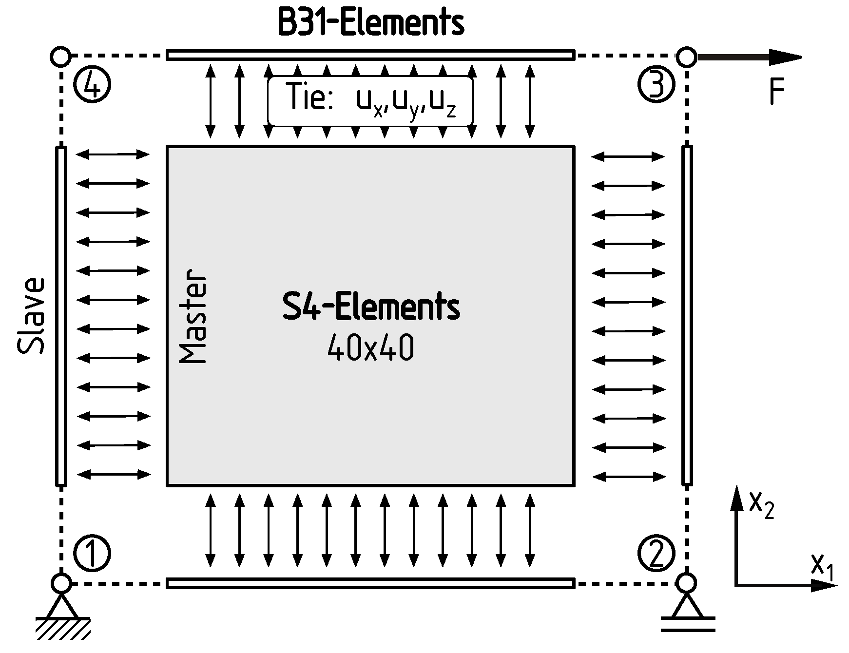
2.2. FEM Reference Model

The FEM reference model is used to validate the analytical shear panel theory, enabling an investigation of the assumptions regarding stress state and stiffness behaviour, which are critical for its application as a modeling technique in preliminary design. For the creation of the FEM reference model, the commercial software Abaqus was used. The model was parametrized to vary the shape and stiffness of the structural elements. The panel and bars were modelled as separate parts, as seen in Figure 3. The panel was discretized using a 40 × 40 grid with S4 shell elements, while the bars were discretized with 40 B31 beam elements. By using a generalized beam section, the axial and bending stiffness of each bar could be controlled independently. To ensure a continuous connection for force transfer and to create hinge-like behaviour at the corners, the translational degrees of freedom of the bars (slave) and panel (master) were coupled along shared edges. The shear panel was statically determined, with a shear load F applied as a concentrated force at corner node 3. The displacement at the loaded corner was measured to calculate the stiffness k F E M = F / u 3 , 1 of the shear panel. Additionally, stress distributions within the shear panel and along its edges were measured.

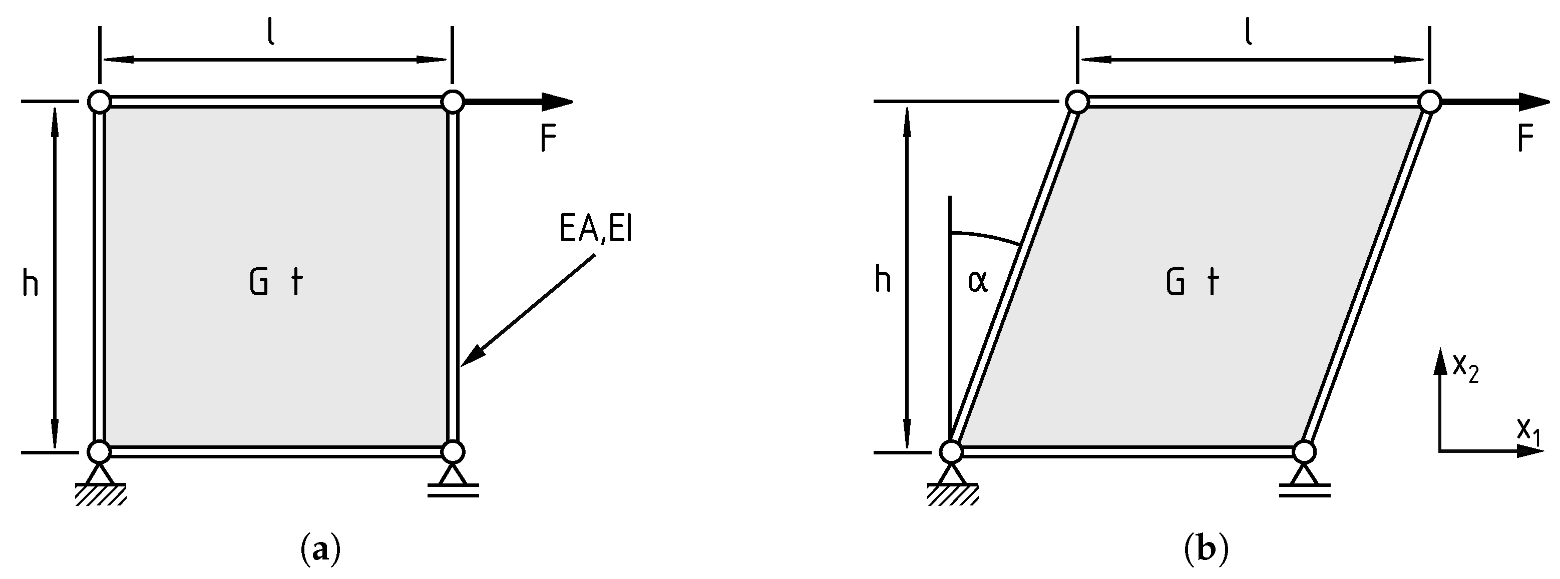
2.3. Definition of Parameter Study for the Rectangular and Parallelogram Panel

In order to check the validity of the shear panel assumptions, the reference model is used. This study looks at two special geometry cases, the rectangle and parallelogram, as shown in Figure 4. The isotropic material for the panel and bars is chosen as steel (E = 210,000   MPa ,   ν   =   0.3 ). The length ( l   =   100   mm ), aspect ratio ( A R   =   a / l   = 1   ) and section properties ( G t   =   80770   N / mm ) of the panel remain constant, while the cross-sectional area ( A     [ 1 ,   10 6 ]   mm 2 ) and second moment of area ( I     [ 1 ,   10 10 ]   mm 4 ) of the bars as well as the parallelogram angle (α ∈ [0, 45]°) are varied. The force is chosen as F   =   100   N to introduce a shear flow of 1   N / mm for the rectangular case.
In this study, the shear panel theory is considered to be valid if the reference model has the same stiffness behaviour and the same stress state as the analytical solution. Therefore, the stiffness of the panel is measured, and the difference is calculated as follows:
k d i f f = k S P T k F E M k F E M .
The reference model and the analytical solution have the same stiffness behaviour when k d i f f   =   0 . As in the derivation of the shear panel theory, pure constant shear stress is assumed at the panel edges, and the stress components in the reference model along the edges are evaluated. It is also checked if the stress state is constant inside the panel.

3. Results

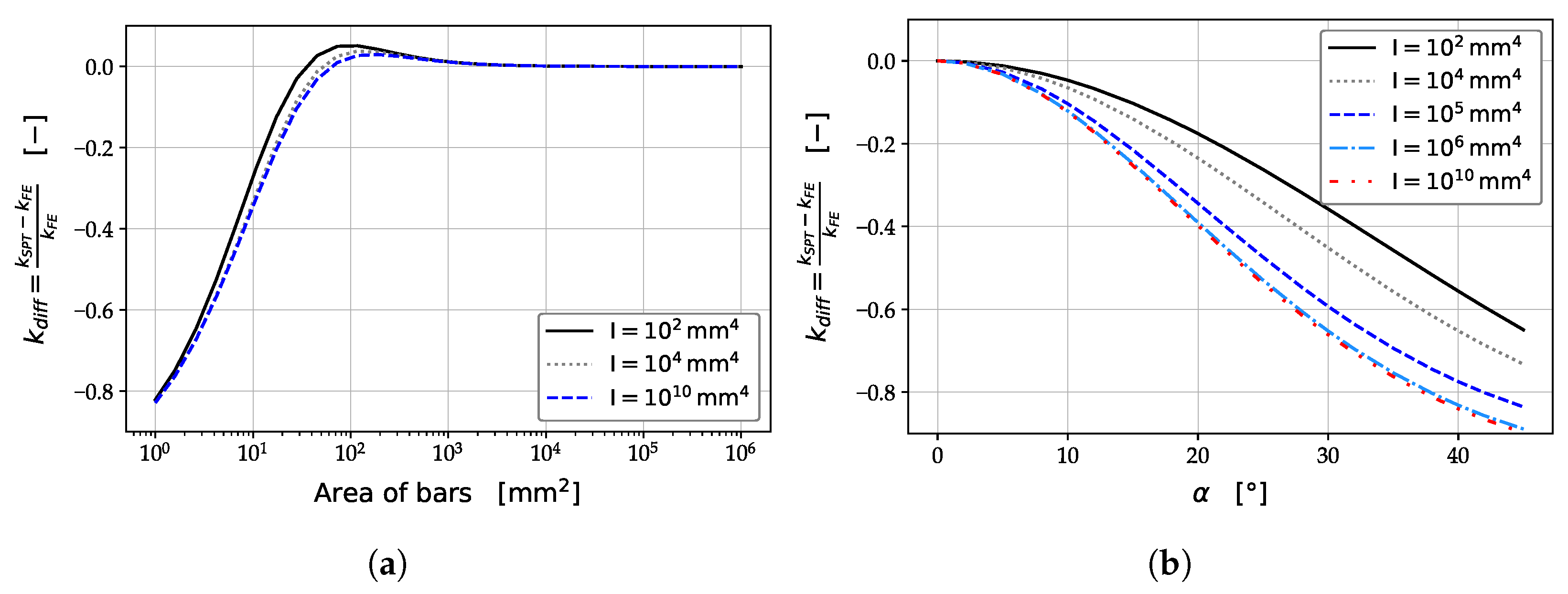
3.1. Parameter Study: Rectangular Shear Panel

First, the results of the stiffness analysis of the rectangular shear panel are presented, before the stress state is investigated. Figure 5a depicts the deviation between the stiffnesses calculated by the analytical and reference models as a function of the cross-sectional area and the second moment of area of the bars. For low axial stiffness, the analytical model underestimates stiffness compared to the reference model, leading to significant deviations. A minor dependence on bending stiffness is observed. However, the deviation decreases with increasing axial stiffness and becomes negligible for sufficiently large values, showing no dependence on the second moment of area.
Figure 6 depicts the stress components for different cross-sectional areas of the bars along the edge 1–2 of the shear panel, see Figure 3. For large areas, a constant pure shear stress state develops along the edge, in accordance with the shear panel theory ( τ 12 = 1   MPa , σ 11 = σ 22 = 0   MPa ), and the same applies to the stress state inside the panel.

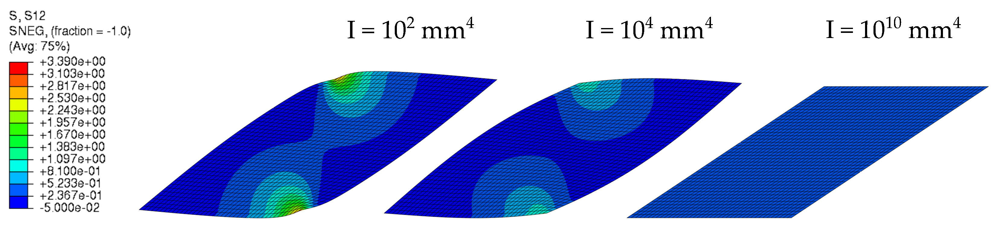
3.2. Parameter Study: Parallelogram Shear Panel

Based on the previous study on the rectangular shear panel, for the study of the parallelogram panel, the cross-sectional area of the bars was chosen to be A   =   10 8   mm 2 to ensure zero deviation between the models for an angle of 0° degrees. Figure 5b shows the deviation in stiffness behaviour as a function of the angle for different second moments of area. In contrast to the rectangular panel, the deviation in stiffness is a function of the second moment of area. Furthermore, significant deviations can be observed between the models for parallelogram panels. However, the solutions converge for large values of the second moment of area.
Figure 6 shows the stress components along the edge 1–2 for the 45°-degree shear panel for various values of the second moment of area. For large values of the second moment of area, the stress components become constant, but are not equal to the analytical solution given in Equation (2). Additionally, the normal stress components do not vanish at the edges of the panel, contradicting the assumption of pure shear stress along the edges.
The deformed contour plots for shear stress of the panels are shown in Figure 7. For large values of the second moment of area, the shear stress inside the panel becomes constant. The same applies to the other stress components. It is also notable that the edges of the shear panel do not remain straight for low second moments of area.

4. Discussion

The comparison of the analytical solution with the FEM reference model confirms that the rectangular shear panel behaves as expected in the stiffness and stress distributions for large axial stiffness of the bars. However, for low axial stiffness, increased elongations of the bars introduce additional stresses that are not considered in the shear panel theory, as the compatibility conditions between panel and bars are neglected. This observation is consistent with the validity condition for the 1D shear panel, as defined in Equation (1). Furthermore, the normal and shear stresses are decoupled, leading to no contraction of the panel under shear loading.
The parameter studies of the parallelogram panel showed that the stress state inside the shear panel as well as the stiffness behaviour do not conform to the analytical solution. In contrast to the rectangular panel, shear stresses in the parallelogram panel are coupled with normal stresses, as described in Equation (2), causing the panel to contract under shear loading. The shear panel theory has no compatibility conditions, allowing free contraction without inducing stresses. However, the presence of stiff bars restricts this contraction, inducing additional stresses. Consequently, the assumptions regarding the stress state, particularly pure shear along the panel edges, are invalid. Additionally, a high bending stiffness of the bars is required to ensure compatibility between adjacent panels. In a real structure, adjacent shear panels can create an apparent high bending stiffness by cancelling out normal stresses, as seen in diagonal tension beams [21,22].

5. Conclusions

This study showed that the assumptions of the rectangular shear panel cannot be directly transferred to the parallelogram shear panel, as the coupling of normal and shear stresses introduces additional compatibility issues. The stress state as well as the stiffness behaviour are not accurately described through the assumptions. Therefore, caution must be exercised when using the shear panel theory for non-rectangular shear panels. Based on the findings, the shear panel theory for the parallelogram panel should reformulated. Further studies should investigate the concept of smeared properties for structures where the normal stiffness of the bars is not significantly greater than that of the panel, as is often the case in real structures.

Author Contributions

Conceptualization, M.B. and K.-U.S.; methodology, M.B.; formal analysis, M.B.; investigation, M.B.; resources, K.-U.S.; writing—original draft preparation, M.B.; writing—review and editing, M.B. and K.-U.S.; visualization, M.B.; supervision, K.-U.S.; project administration, K.-U.S. All authors have read and agreed to the published version of the manuscript.

Funding

The work in this paper was realized in the course of the Technologietransfer-Programms Leichtbau (TTP-LB), funded by the Federal Ministry of Economic Affairs and Climate Action (Bundesministerium für Wirtschaft und Klimaschutz) of the German government under the funding code 03LB3086H.

Institutional Review Board Statement

Not applicable.

Informed Consent Statement

Not applicable.

Data Availability Statement

Data are contained within the article.

Conflicts of Interest

The authors declare no conflicts of interest.

Abbreviations

The following abbreviations are used in this manuscript:
FEMFinite Element Method
SPTShear Panel Theory

References

  1. Parolin, G.; Borges, A.T.; Santos, L.C.; Borille, A.V. A tool for aircraft eco-design based on streamlined Life Cycle Assessment and Uncertainty Analysis. Procedia CIRP 2021, 98, 565–570. [Google Scholar] [CrossRef]
  2. Lyssakow, P.; Krause, M.; Friedrich, L.; Schröder, K.-U. Towards a coupled structural and economical design procedure of unstiffened isotropic shell structures. Thin-Walled Struct. 2019, 145, 106416. [Google Scholar] [CrossRef]
  3. Lyssakow, P.; Yang, J.; Krause, M.; Schröder, K.-U. Analysis of mass and cost drivers of unstiffened isotropic shell structures considering their imperfection sensitivity. Thin-Walled Struct. 2021, 159, 107221. [Google Scholar] [CrossRef]
  4. Quatmann, M.; Reimerdes, H.-G. Preliminary design of composite fuselage structures using analytical rapid sizing methods. CEAS Aeronaut. J. 2011, 2, 231–241. [Google Scholar] [CrossRef]
  5. Mittelstedt, C.; Schröder, K.-U. Local postbuckling of hat-stringer-stiffened composite laminated plates under transverse compression. Compos. Struct. 2010, 92, 2830–2844. [Google Scholar] [CrossRef]
  6. Mittelstedt, C.; Erdmann, H.; Schröder, K.-U. Postbuckling of imperfect rectangular composite plates under inplane shear closed-form approximate solutions. Arch. Appl. Mech. 2011, 81, 1409–1426. [Google Scholar] [CrossRef]
  7. Krause, M.; Lyssakow, P.; Friedrich, L.; Schröder, K.-U. Panel buckling of stiffened shell structures with torsional stiff stringer. Aerosp. Sci. Technol. 2020, 107, 106257. [Google Scholar] [CrossRef]
  8. Krause, M.; Lyssakow, P.; Schröder, K.-U. Improved approach for the panel buckling calculation of stiffened shell structures with torsional stiff stringer. Thin-Walled Struct. 2022, 171, 108829. [Google Scholar] [CrossRef]
  9. Krause, M.; Lyssakow, P.; Schröder, K.-U. Minimum stiffness criterion for ring frames of stringer frame stiffened shell structures. Thin-Walled Struct. 2023, 182, 110155. [Google Scholar] [CrossRef]
  10. Grihon, S.; Krog, L.; Bassir, D. Numerical Optimization applied to structure sizing at AIRBUS: A multi-step process. Int. J. Simul. Multidisci. Des. Optim. 2009, 3, 432–442. [Google Scholar] [CrossRef]
  11. Richstein, R.; Schröder, K.-U. Characterizing the Digital Twin in Structural Mechanics. Designs 2024, 8, 8. [Google Scholar] [CrossRef]
  12. Wiedemann, J. Leichtbau: Elemente und Konstruktion, 3rd ed.; Springer: Berlin/Heidelberg, Germany, 2007. [Google Scholar]
  13. VDI 2221—Part 1 (2019), Design of Technical Products and Systems—Model of Product Design; Verein Deutscher Ingenieure: Harzgerode, Germany, 2019.
  14. Kurrer, K.-E. The History of the Theory of Structures: From Arch Analysis to Computational Mechanics; Ernst: Berlin, Germany, 2008; ISBN 3433018383. [Google Scholar]
  15. Hoogenboom, P.C.J.; Blaauwendraad, J. Quadrilateral shear panel. Eng. Struct. 2000, 22, 1690–1698. [Google Scholar] [CrossRef]
  16. Curtis, H.D.; Greiner, G.P. A stress-based quadrilateral shear panel. Finite Elem. Anal. Des. 1996, 21, 159–178. [Google Scholar] [CrossRef]
  17. Chen, H.C. A simple quadrilateral shear panel element. Commun. Appl. Numer. Methods 1992, 8, 1–7. [Google Scholar] [CrossRef]
  18. Garvey, S.J. The Quadrilateral ‘Shear’ Panel: The Peculiar Stressing Problems Arising in the Structure of the Non-Rectangular Swept Wing. Aircr. Eng. Aerosp. Technol. 1951, 23, 134–144. [Google Scholar] [CrossRef]
  19. Mittelstedt, C. Structural Mechanics in Lightweight Engineering; Springer: Cham, Switzerland, 2021. [Google Scholar]
  20. Dieker, S.; Reimerdes, H.G. Elementare Festigkeitslehre im Leichtbau; Donat Verlag: Bremen, Germany, 1992; ISBN 3924444587. [Google Scholar]
  21. Wagner, H. Ebene Blechwandträger mit sehr dünnem Stegblech. Zeitschrift für Flugtechnik und Motorluftschiffahrt 1929, 20, 200–207, 227–233, 256–262, 279–284, 306–314. [Google Scholar]
  22. Kuhn, P.; Peterson, J.P.; Levin, L.R. A Summary of Diagonal Tension–Part I: Methods and Analysis; NACA TN 2661; NASA: Washington, DC, USA, 1952.
Figure 1. Idealization of an I-beam under bending moment and shear loading as a shear panel model showing stress distributions, adapted from Dieker and Reimerdes [20].
Engproc 90 00023 g001
Figure 2. (a) Free-body diagram of rectangular shear panel. (b) Parallelogram panel under shear load. (c) Section cut through parallelogram panel, adapted from [19].
Engproc 90 00023 g002
Figure 3. Exploded-view drawing of the FEM reference model, showing boundary conditions and ties.
Engproc 90 00023 g003
Figure 4. Parameter study of (a) the rectangular panel and (b) the parallelogram panel.
Engproc 90 00023 g004
Figure 5. Comparison of the stiffness difference between the analytical and reference model solutions: (a) Influence of the cross-sectional area and second moment of area of the bars for a rectangular shear panel. (b) Influence of the angle and second moment of area on a parallelogram shear panel with a cross-sectional area of A = 10 8   mm 2 .
Engproc 90 00023 g005
Figure 6. Stress components (a) σ 11 , (c) σ 22 and (e) τ 12 along edge 1–2 of the rectangular shear panel for different cross-sectional areas of the bars. Stress components (b) σ 11 , (d) σ 22 and (f) τ 12 along edge 1–2 of the 45° parallelogram shear panel for different values of the second moment of area and a cross-sectional area of A = 10 8   mm 2 .
Engproc 90 00023 g006
Figure 7. Deformed τ 12 -contour plot of the 45° parallelogram shear panel for different values of the second moment of area.
Engproc 90 00023 g007
Disclaimer/Publisher’s Note: The statements, opinions and data contained in all publications are solely those of the individual author(s) and contributor(s) and not of MDPI and/or the editor(s). MDPI and/or the editor(s) disclaim responsibility for any injury to people or property resulting from any ideas, methods, instructions or products referred to in the content.

