Proceeding Paper

Enhancing GNSS Robustness in Automotive Applications with Supercorrelation: Experimental Results in Urban Scenarios †

Focal Point Positioning Ltd., Cambridge CB4 3NP, UK
*
Author to whom correspondence should be addressed.
Presented at the European Navigation Conference 2024, Noordwijk, The Netherlands, 22–24 May 2024.
Eng. Proc. 2025, 88(1), 75; https://doi.org/10.3390/engproc2025088075
Published: 10 September 2025
(This article belongs to the Proceedings of European Navigation Conference 2024)

Abstract

Mitigating multipath interference is one of the biggest challenges in radio positioning. The Supercorrelation™ technology developed via Focal Point Positioning (FPP) suppresses multipath interference by performing long coherent integration while undergoing complex motion to isolate the Line-Of-Sight (LOS) signals from the unwanted multipath interference.This article presents live results with a Supercorrelating Global Navigation Satellite System (S-GNSS) Software-Defined Radio (SDR), demonstrating significantly suppressed multipath to regain position accuracy.

1. Introduction

Multipath interference significantly degrades Global Navigation Satellite System (GNSS) positioning accuracy and reliability in challenging automotive environments like urban canyons [1,2,3,4,5]. This degradation poses critical challenges for the safety and integrity of autonomous driving and Advanced Driver-Assistance Systems (ADAS), which demand continuous and trustworthy positioning [6,7,8,9]. To mitigate these effects, advanced techniques have been developed to ensure only multipath-free Line-Of-Sight (LOS) signals are processed in the navigation solution, using methods like 3D mapping or machine learning-based signal classification [10,11,12,13,14]. Integrating patented Supercorrelation™ technology into a GNSS receiver [15,16,17], developed by Focal Point Positioning (FPP) under a European Space Agency (ESA) NAVISP project to create a Supercorrelating Global Navigation Satellite System (S-GNSS) receiver, offers a unique solution to multipath interference in challenging automotive environments by filtering incoming signals by angle of arrival in software processing alone. This ensures only multipath-free Line-Of-Sight (LOS) signals are processed in the navigation solution. Furthermore, this technique provides a sensitivity boost to the LOS signals [18], an enhancement previously only attainable through large, complex, and costly antenna hardware [19,20,21] such as choke ring arrays [22,23]. This sensitivity boost is invaluable in extending the availability of accurate GNSS positioning when signal strengths drop or background noise increases [24,25], thereby directly addressing the core reliability challenges for vehicular systems.
In this work, we present initial experimental results with an S-GNSS® receiver in urban scenarios; areas where traditional processing struggles to provide high accuracies.
Results show significant improvements in GNSS robustness and accuracy, hinting at the full potential of S-GNSS in a final Advanced Driver-Assistance System (ADAS) solution. These findings pave the way for reliable GNSS measurements in the toughest automotive environments, ultimately propelling the safe and efficient deployment of semi and fully autonomous vehicles.
The rest of the article is structured as follows: Section 2 briefly introduces S-GNSS. Section 3 presents the receiver architecture, and Section 4 exhibits the demonstrator platform. Section 5 defines the test setup, and Section 6 shows the results. Finally, the conclusions are drawn in Section 7.

2. S-GNSS Background and Operation

S-GNSS suppresses multipath interference through extended correlation by correcting the receiver clock, the receiver motion, and the motion of the satellite during accumulation [17]. Longer correlation allows a separation between the correct LOS signal and multipath interference using the carrier frequency offset [15,26,27]. S-GNSS is ideal for urban environments with challenging multipath interference [28,29] and has shown benefits when integrated with 3D mapping [30] and inertial navigation systems [31]. Furthermore, it has been adopted by mass-market receivers [16], has been tailored for easy integration into smartphones [32], and is being integrated into the automotive sector [33].

3. FPP S-GNSS Receiver Architecture

With the support of ESA under the NAVISP Element 2 program (https://navisp.esa.int/element/competitiveness (accessed on 15 May 2023)), FPP is designing, building, and deploying an S-GNSS Software-Defined Radio (SDR) real-time receiver, which is a hardware and software platform, for the development and demonstration of the SGNSS technology. The approach of this receiver is to use hardware Commercial-Off-The-Shelf (COTS) components for the Radio-Frequency Front-End (RFFE) and an SDR approach for the GNSS processing in the software. Initial results in controlled laboratory conditions showed effective results in suppressing multipath [15]. However, a technology demonstrator records and evaluates live scenarios in this paper.
Figure 1 shows the main building blocks of the S-GNSS hardware: an NTLab® NT1065-USB3 RF IC EVALUATION KIT is the RFFE, a Linux-based Next Unit of Computing (NUC) Personal Computer (PC) (Intel Rugged NUC 13 Pro NUC13ANFi7) is the processing unit of the receiver, and an FPP Inertial Sensor Data Logging and Streaming Unit (DLSU) is the inertial sensor data source. This paper focuses on the live trialling results of the S-GNSS SDR with inertial integration from the DLSU and S-GNSS processing.
The NTLab® NT1065-USB3 RFFE is configured for dual-band operation and receives the L1 and L5 frequency bands with a real-valued sample rate of approximately 48 MHz and uses 2-bit precision. The DLSU contains a low-cost Inertial Measurement Unit (IMU) and an F9T L1/L5 u-blox GNSS receiver. The IMU comprises the FXOS8700CQ 3-axis accelerometer and 3-axis magnetometer unit and the FXAS21002C 3-axis gyroscope unit. The u-blox receiver is used to time-stamp the inertial measurements and to provide the S-GNSS SDR with assistance data for the satellite orbits and corrections.
The S-GNSS SDR is completely developed from the ground up by FPP to be fast and reliable. It can perform all vital GNSS processing, including acquisition, tracking, and Position, Velocity, and Time (PVT) calculation. However, the SDR does not decode the navigation message but uses an external assistance source. The SDR can process GPS L1 C/A, GPS L5I/Q, Galileo E1B/C, and Galileo E5aI/Q signals. However, in this paper, only the GPS L1 C/A and Galileo E1C signals will be used for a minimal demonstration. In the current version, it can track at least 40 signals in real-time in live operation with three correlation taps each (i.e., complex early, prompt, and late).
Additionally, the receiver has some advanced features. First, it applies sensor fusion with an IMU (located inside the FPP DLSU) for improved positioning in GNSS-challenged conditions. Second, it can use both scalar and vector tracking for robust tracking in harsh conditions (details on vector tracking capabilities will be showcased in a future publication). Lastly, it implements S-GNSS to suppress multipath. In particular, the sensor fusion and S-GNSS results will be showcased in this paper.

4. Demonstrator

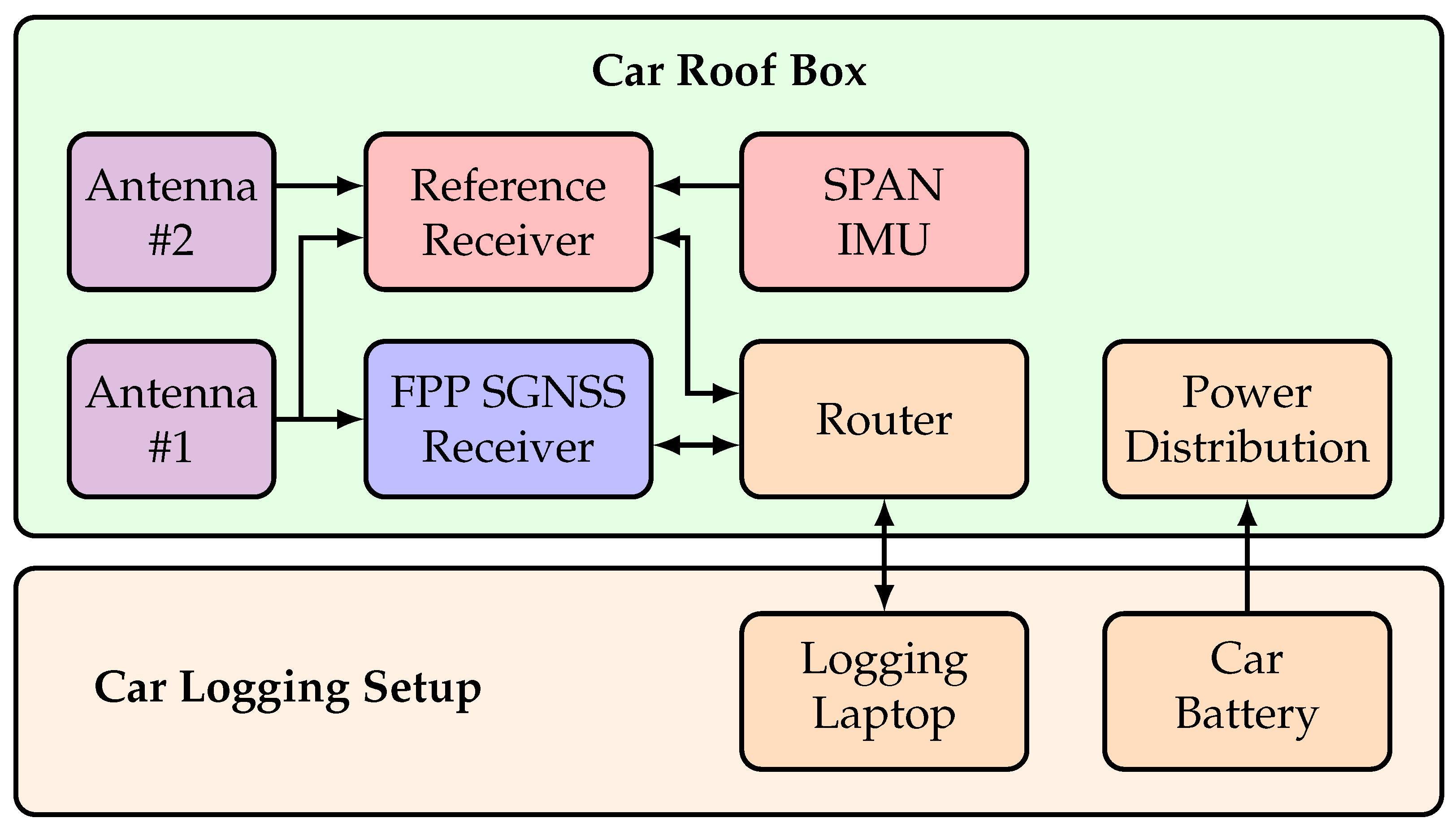
Figure 2 describes the demonstrator setup. Most electronics are housed in a car roof box, with some logging support and power from inside the car.
Inside the car roof box, there is the FPP GNSS receiver, as described in Section 3. Additionally, a Ground Truth System (GTS) is used to verify the receiver performance. The GTS comprises of a Novatel PwrPak7 GNSS receiver and a tactical-grade Novatel SPAN IMU-ISA-100C IMU. Two geodetic-grade Novatel VEXXIS GNSS-850 antennas are used in the setup. A router connects the two receivers to a logging laptop inside the car. Finally, a 12V car battery inside the car is used to power the system.
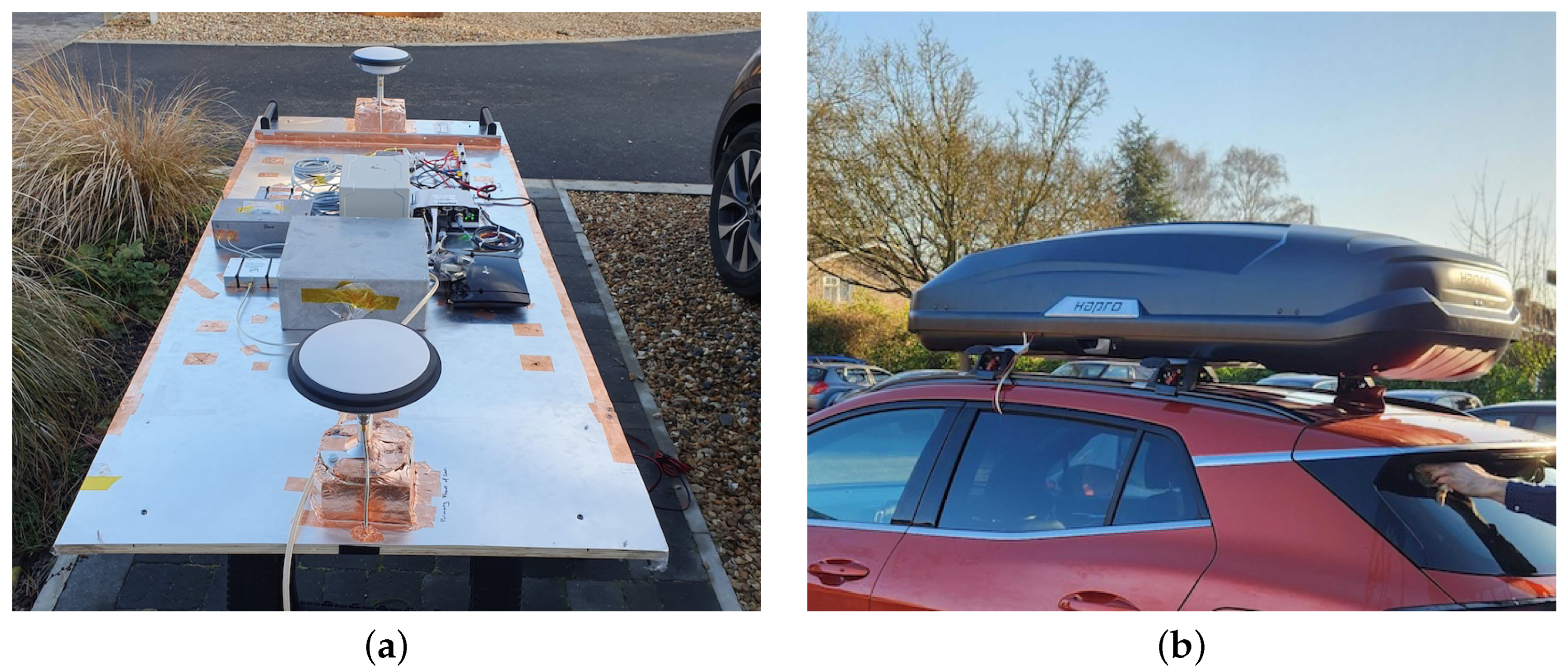
Figure 3 shows the demonstrator platform. On the left, the individual components inside the roof box are visible, and on the right, the complete setup inside the car roof box mounted on top of a car is shown.

5. Test Setup

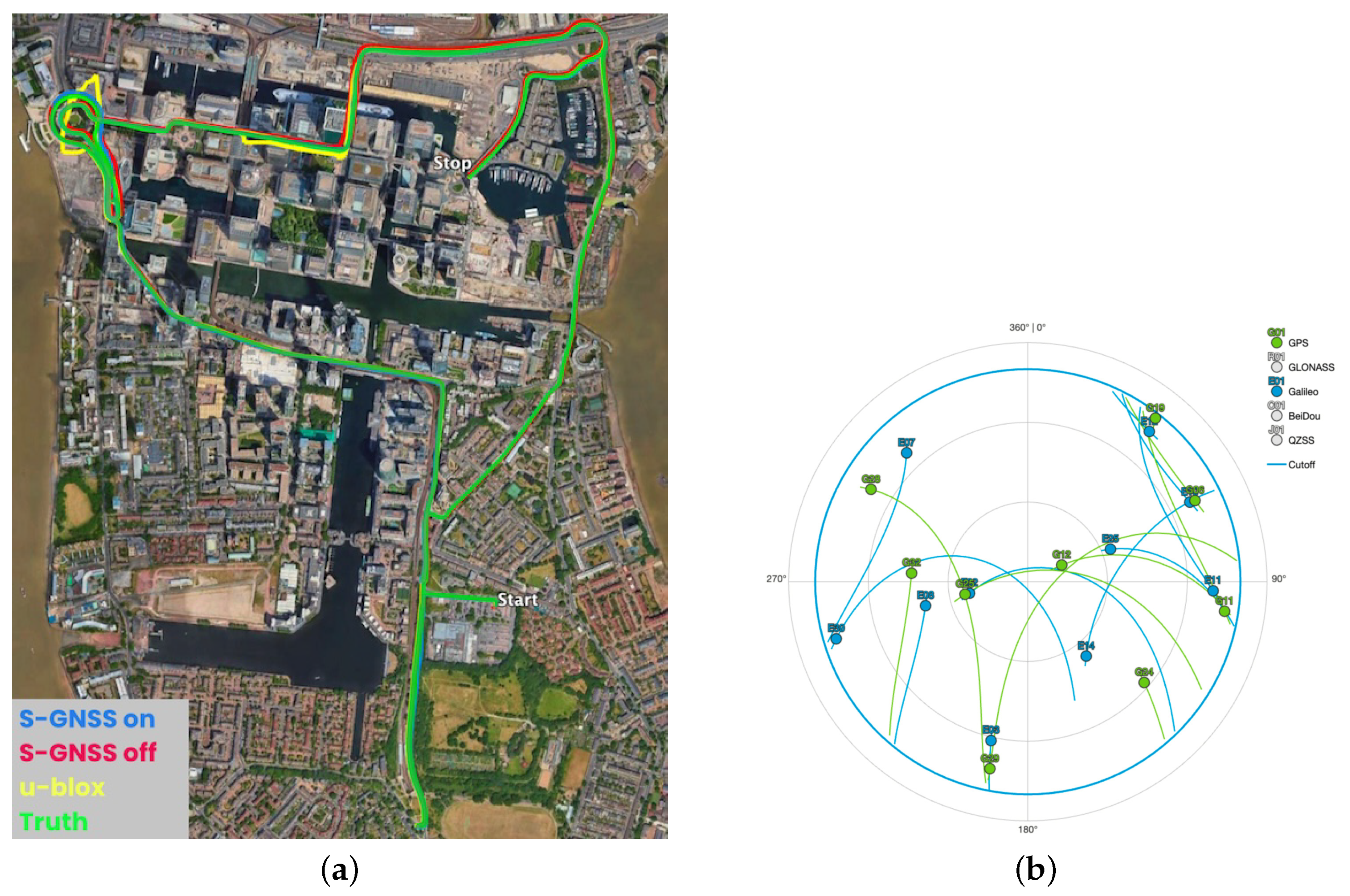
The demonstrator described in Section 4 was used for data-capturing runs. However, for this paper, we will focus on a challenging scenario at Canary Wharf in downtown London. This scenario includes many deep urban sections with significant multipath challenges for GNSS receivers [34].
Figure 4 shows the recording path (left) and the skyplot over time for the satellites in view during the recording (right).

6. Results

In the results, we compare the FPP S-GNSS SDR with and without S-GNSS processing enabled (and using only GPS L1 and Galileo E1 with low-cost IMU), against the GTS (i.e., high-grade positioning solution with multi-band multi-signal GNSS with real-time kinematic (RTK) in post processing and tactical-grade IMU). Also included for comparison are the outputs from the u-blox F9T receiver inside the DLSU, which is a low-cost mass-market receiver using L1/L5 dual-band processing for GPS, Galileo, and BeiDou, but which is not sensor-aided (the sensor-aided version is not yet commercially available). While there is no like-for-like comparison between the single frequency, dual constellation, sensor-aided positioning outputs from the S-GNSS SDR and those from the dual frequency, triple constellation, non-sensor-aided u-blox receiver, the simple comparison still provides a benchmark for FPP’s receiver versus a commercial system. First, some interesting segments of the data capture are shown, followed by pseudorange error analysis, and finally, PVT error analysis.

6.1. Interesting Case Studies

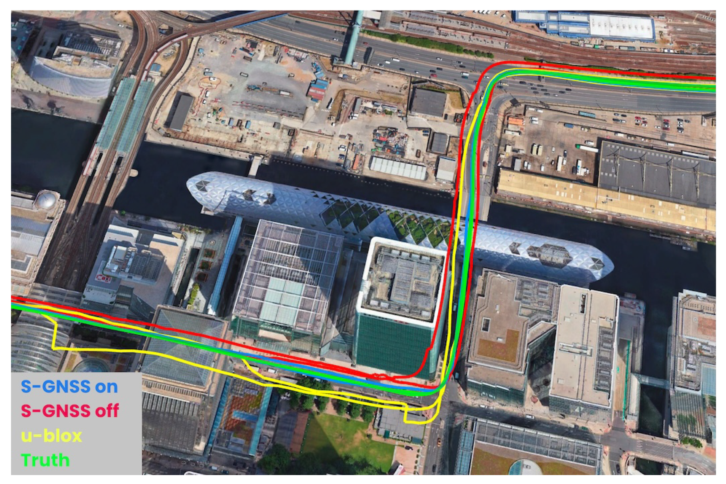
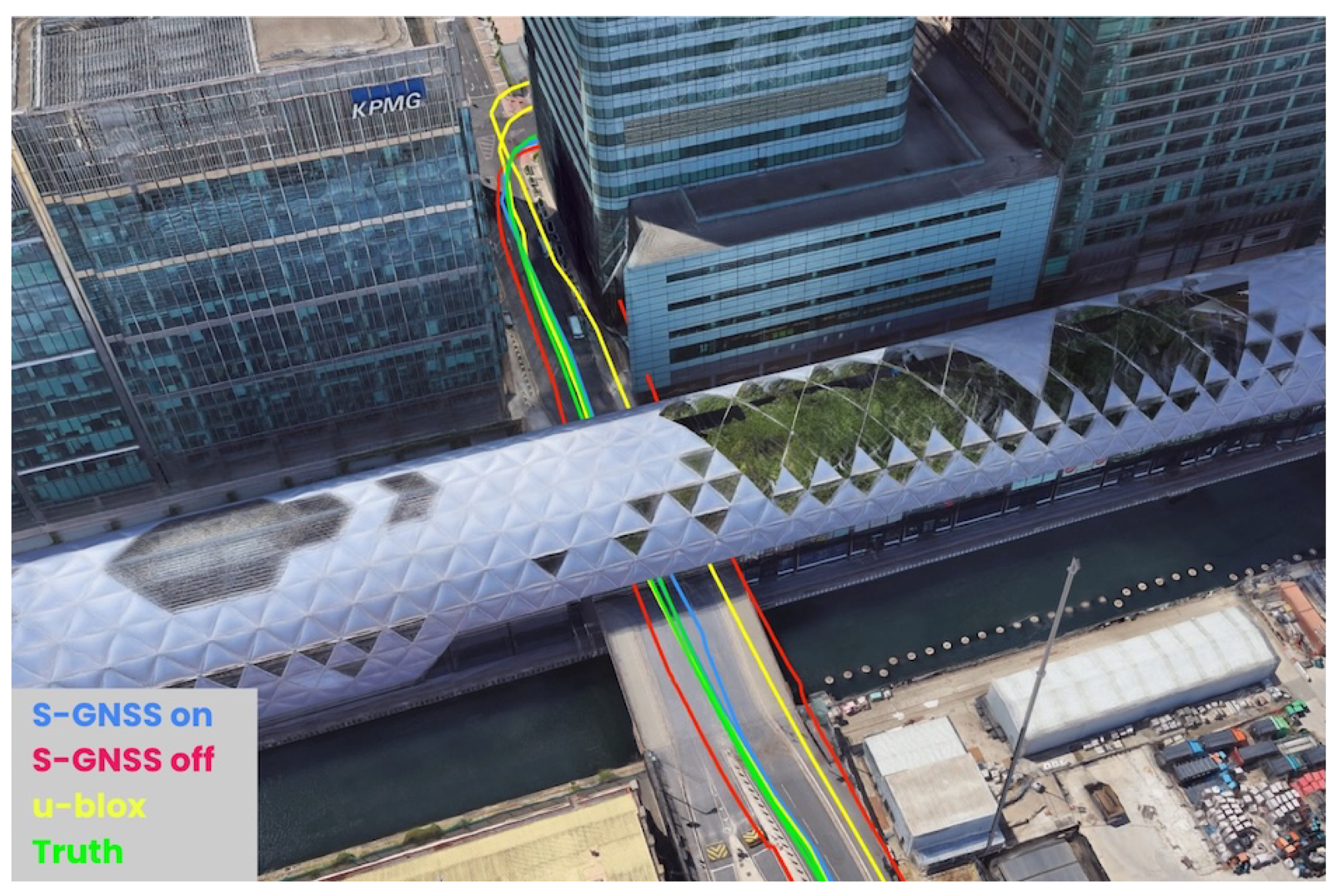
Figure 5 shows the first interesting case. The demonstrator enters the figure from the left (West) and drives immediately underneath a rail bridge, then continues to drive East along the road between multiple high-rise buildings, before turning left (North) and driving through a tunnel which passes underneath a shopping mall. This route results in temporary signal outages and very poor GNSS reception. Both the SDR and the GTS solutions follow the shape of the road reliably, mostly due to aiding from the respective inertial sensors. However, the u-blox which does not have sensor-aiding has significant overshoots and drift from the road.
The SDR without S-GNSS-enabled generally follows the trajectory but has a bias as expected with inertial aiding in strong multipath environments. However, notice that the bias is removed with S-GNSS switched on, and road-level precision is achieved again.
Figure 6 presents a rotated view of the same case showing the nature of the deep urban canyon as well as the tunnel underneath the shopping mall. There are two passes on this section of the road, hence the dual lines from each colour. This is a particularly interesting case for ADAS. For both the S-GNSS off and u-blox receiver solutions, one track is completely off the road; however, with S-GNSS enabled, lane-level precision is regained when compared to the GTS. Note that the S-GNSS receiver does not utilise RTK or Precise Point Positioning (PPP) techniques to achieve this accuracy.
Figure 7 shows the second interesting case. The demonstrator drives around multiple roundabouts, including one entirely within a tunnel (the outer roundabout at the top (North) of the figure) with tall buildings to the North and East. As with the previous case, the S-GNSS and the GTS follow the road, but the mass market receiver and the SDR without S-GNSS have inferior performance. The u-blox receiver is particularly impacted in the tunnel section due to the lack of sensor-aiding.

6.2. Pseudorange Error Analysis

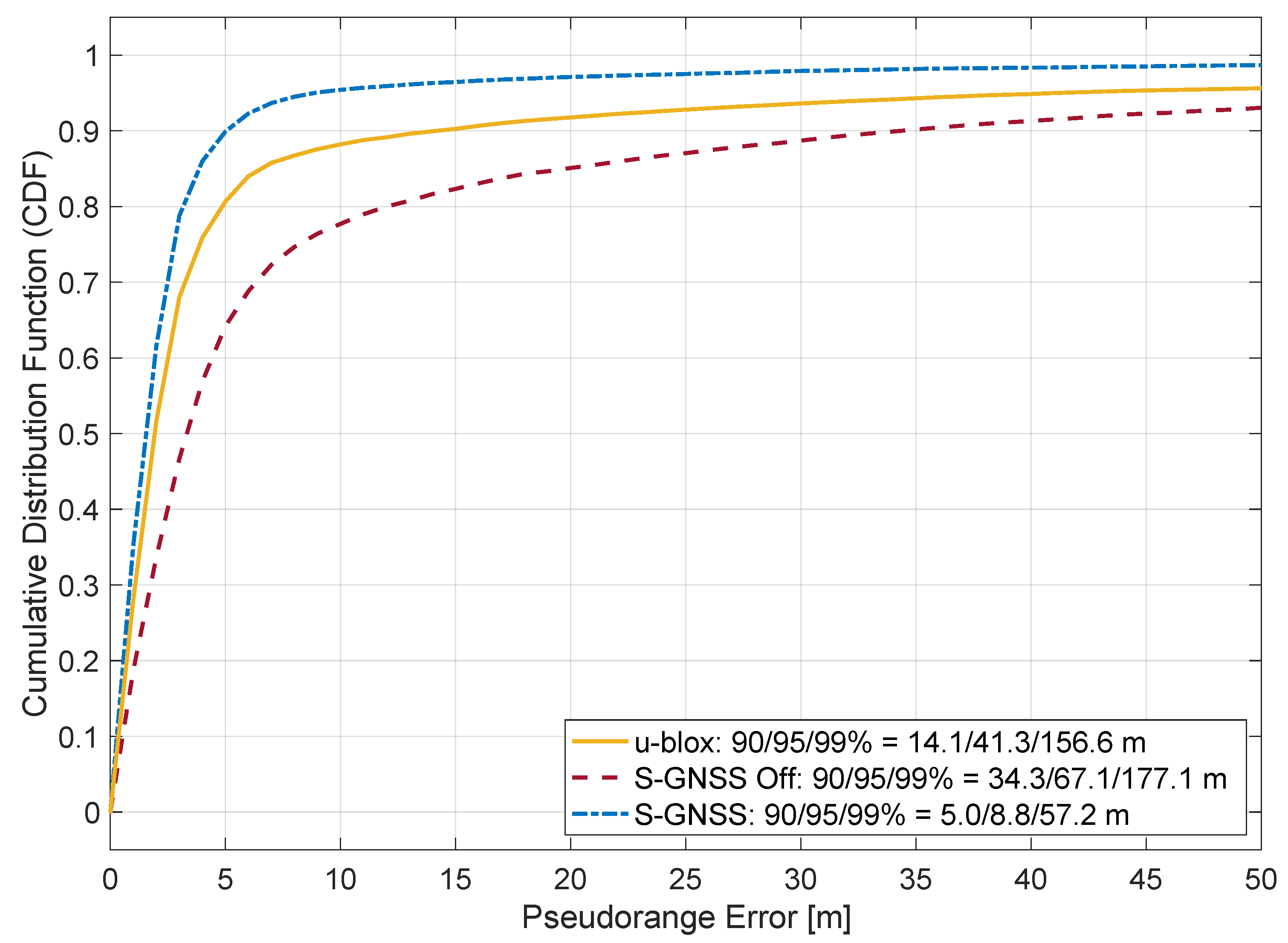
Figure 8 shows the pseudorange error Cumulative Distribution Function (CDF) for GPS L1 C/A and Galileo E1C signals. The plot shows the performance with S-GNSS enabled and disabled. The inclusion of S-GNSS processing results in improved pseudorange performance, surpassing the mass market receiver.
Only signals with carrier-to-noise density ratio (C/N0) values exceeding 25 dBHz are included in this analysis. The C/N0 values for the u-blox are the reported values from the receiver. The C/N0 for S-GNSS-disabled are the values reported by SDR during tracking. However, it does not mean the tracking is aborted; only the resultant pseudoranges are not used for this analysis. Finally, the C/N0 values for the S-GNSS-enabled are the values after the Supercorrelation processing has been applied. It means that signals that are reporting much lower C/N0 values than 25 dBHz during tracking are processed and have the opportunity to improve their effective C/N0 due to the multipath suppressing capabilities of Supercorrelation. Note that the individual C/N0 filters, in conjunction with different numbers of signals in tracking, result in a different number of samples for each CDF curve.
In this scenario, S-GNSS On retains approximately 70% of the measurements, and S-GNSS Off retains 46%. The difference can be partially explained by SC increasing the CN0 of several signals due to improved coherent integration and by suppressing multi-path (note that the presence of multipath signals negatively biases C/N0 estimation, resulting in more signals being filtered). However, deeper analysis is required to fully characterise the phenomena. Furthermore, we would like to emphasise that vector tracking would attempt to track all signals that would’ve been visible in an open sky, which results in significant phantom signal tracking. As VT is affected by S-GNSS, additional effects could cause the differences.

6.3. Positioning Error Analysis

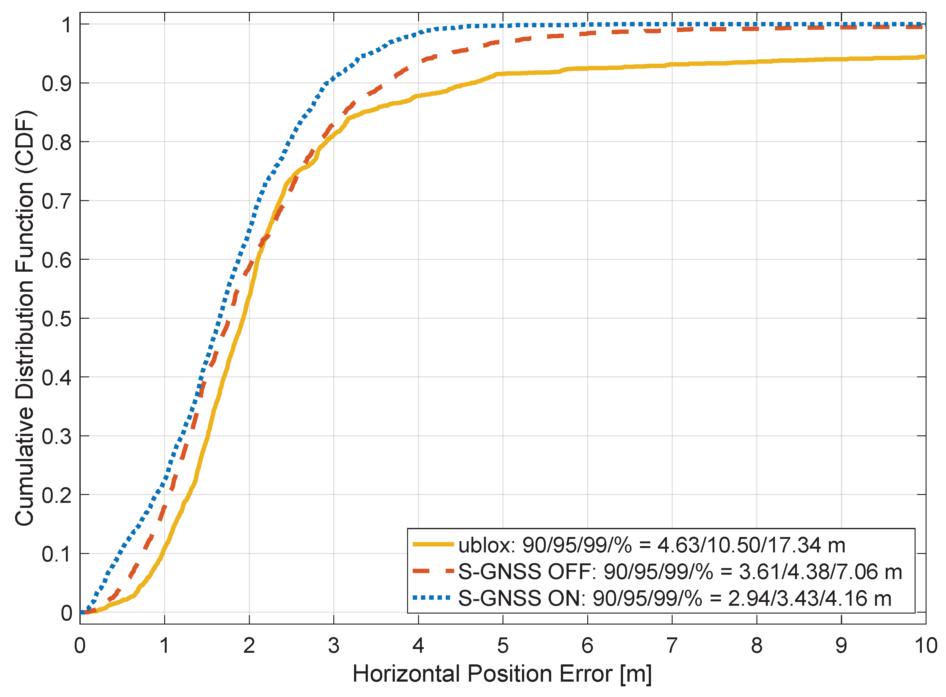
Figure 9 compares the horizontal position error CDF between the receivers and the GTS. As with the previous results, the S-GNSS-enabled receiver recovers position accuracy relative to the S-GNSS-disabled results. The S-GNSS-enabled receiver achieves a horizontal error below 2.94 m for 90% of the time.
The S-GNSS receiver also outperforms the mass market receiver while using fewer GNSS constellations and fewer frequency bands; however, it benefits from sensor-aiding, which is not available to the u-blox receiver. Given this lack of sensor-aiding for the u-blox receiver, we have deliberately excluded the tunnel section shown in Figure 7 from the position domain error analysis to allow a more fair comparison between the u-blox device and our S-GNSS receiver. The results demonstrate the significant PVT benefits that S-GNSS provides. Furthermore, the presented data represents a challenging urban scenario recorded in London, UK, demonstrating the benefits of robust navigation in severe multipath-interfered scenarios.

7. Conclusions

This paper showcases a S-GNSS demonstration platform with live data recordings. The demonstrator allows simple data collection for automotive scenarios to demonstrate the benefits that S-GNSS could provide to ADAS.
The results show that Supercorrelation processing significantly improves the measurement and position domain performance of a single frequency GNSS receiver with inertial aiding in strong multipath environments. Furthermore, the results demonstrate high accuracy for GNSS navigation in challenging urban scenarios.
The current work represents the first live results from a technology demonstrator and will be refined in the future. Therefore, future work includes improving the SDR for multi-frequency operation and more detailed data analysis in diverse settings, extending the current urban datasets and including under foliage scenarios.

Author Contributions

Conceptualization, J.G.G., P.E., J.R.v.d.M., H.M. and R.F.; methodology, J.G.G., J.R.v.d.M., P.E. and H.M.; software, J.G.G., P.E., J.R.v.d.M., H.M., S.B., E.C., J.E., H.E.-M., R.G., C.H., D.J., S.K. and O.K.; validation, J.G.G., P.E. and H.M.; formal analysis, J.G.G., J.R.v.d.M., P.E. and H.M.; investigation, J.G.G., P.E. and H.M.; resources, P.E., R.F. and M.C.; data curation, J.G.G., P.E. and H.M.; writing—original draft preparation, J.R.v.d.M. and J.G.G.; writing—review and editing, J.G.G., J.R.v.d.M., P.E., H.M., M.C. and R.F.; visualization, J.G.G., P.E., J.R.v.d.M. and H.M.; supervision, J.G.G., R.F. and M.C.; project administration, J.G.G., R.F. and M.C.; funding acquisition, P.E., R.F. and M.C. All authors have read and agreed to the published version of the manuscript.

Funding

This work was funded through the ESA project NAVISP-EL2-119.

Institutional Review Board Statement

Not applicable.

Informed Consent Statement

Not applicable.

Data Availability Statement

Data sharing is not applicable to this article.

Conflicts of Interest

All authors were employed by Focal Point Positioning Ltd. at the time of the study. The authors declare that the research was conducted in the absence of any commercial or financial relationships that could be construed as a potential conflict of interest.

Abbreviations

The following abbreviations are used in this manuscript:
C / N 0 carrier-to-noise density ratio
ADASAdvanced Driver-Assistance System
CDFCumulative Distribution Function
COTSCommercial-Off-The-Shelf
DLSUInertial Sensor Data Logging and Streaming Unit
ESAEuropean Space Agency
FPPFocal Point Positioning
GNSSGlobal Navigation Satellite System
GTSGround Truth System
IMUInertial Measurement Unit
LOSLine-Of-Sight
NLOSNon-Line-Of-Sight
NUCNext Unit of Computing
PCPersonal Computer
PPPPrecise Point Positioning
PVTPosition, Velocity, and Time
RFFERadio-Frequency Front-End
RTKreal-time kinematic
S-GNSSSupercorrelating Global Navigation Satellite System
SDRSoftware-Defined Radio

References

  1. Kaplan, E.D.; Hegarty, C.J. Understanding GPS: Principles and Applications, 2nd ed.; Artech House mobile communications series; Artech House: London, UK, 2006. [Google Scholar]
  2. Groves, P.D. Principles of GNSS, Inertial, and Multisensor Integrated Navigation Systems, 2nd ed.; Artech House: London, UK, 2013. [Google Scholar]
  3. Kuusniemi, H.; Wieser, A.; Lachapelle, G. User-level reliability and quality monitoring in urban personal navigation. GPS Solut. 2004, 8, 249–260. [Google Scholar]
  4. Zhu, N.; Marais, J.; Bétaille, D.; Berbineau, M. GNSS Position Integrity in Urban Environments: A Review of Literature. IEEE Trans. Intell. Transp. Syst. 2018, 19, 2762–2778. [Google Scholar] [CrossRef]
  5. Baselga, S.; García-Asenjo, L. Multipath Mitigation by Global Robust Estimation. J. Navig. 2008, 61, 385–392. [Google Scholar] [CrossRef]
  6. Reid, T.G.R.; Neish, A.M.H.; Walter, T.B.; Enge, P.K. Positioning, navigation, and timing for autonomous vehicles. IEEE Signal Process. Mag. 2018, 35, 42–53. [Google Scholar]
  7. Hsu, L.T. A survey on positioning techniques for autonomous driving. Robotics 2018, 7, 47. [Google Scholar]
  8. Pendão, C.; Silva, I.; Botelho, F.; Silva, H. GNSS Simulation for Automotive: Introducing 3D Scene-Dependent Multipath With CARLA. IEEE Access 2025, 13, 35376–35386. [Google Scholar] [CrossRef]
  9. Liu, C.; Gao, W.; Liu, T.; Wang, D.; Yao, Z.; Gao, Y.; Nie, X.; Wang, W.; Li, D.; Zhang, W.; et al. Design and implementation of a BDS precise point positioning service. Navig. J. Inst. Navig. 2020, 67, 875–891. [Google Scholar] [CrossRef]
  10. Suzuki, T. GNSS positioning using a 3D map. IEEE Trans. Intell. Transp. Syst. 2017, 18, 209–219. [Google Scholar]
  11. Yozevitch, R.; Ben-Moshe, B.; El-Shimoni, B. NLOS classification and mitigation in a dense urban area using a machine learning algorithm. Sensors 2016, 16, 2097. [Google Scholar]
  12. Bassma, G.; Tayeb, S.; Hassan, E.G.; Serge, R.; Esmail, A. A Map-Matching Based Approach to Compute and Modelize NLOS and Multipath Errors for GNSS Positioning in Hard Areas. J. Mob. Multimed. 2017, 13, 256–269. [Google Scholar]
  13. Zhang, T.; Zhou, L.; Feng, X.; Shi, J.; Zhang, Q.; Niu, X. INS-Aided GNSS Pseudo-Range Error Prediction Using Machine Learning for Urban Vehicle Navigation. IEEE Sensors J. 2024, 24, 9135–9147. [Google Scholar] [CrossRef]
  14. Ziedan, N.I. Optimized Position Estimation in Mobile Multipath Environments Using Machine Learning. Navig. J. Inst. Navig. 2023, 70, 1–20. [Google Scholar] [CrossRef]
  15. Garcia, J.G.; van der Merwe, J.R.; Esteves, P.; Jamal, D.; Benmendil, S.; Higgins, C.; Grey, R.; Coetzee, E.; Faragher, R. Development of a Custom GNSS Software Receiver Supporting Supercorrelation. Eng. Proc. 2023, 54, 9. [Google Scholar] [CrossRef]
  16. Inside GNSS. GNSS Supercorrelation to Increase Accuracy Is Basis of New Partnership of u-blox, Focal Point. Available online: https://insidegnss.com/gnss-supercorrelation-to-increase-accuracy-is-basis-of-new-partnership-of-u-blox-focal-point/ (accessed on 29 August 2025).
  17. Focal Point Positioning. Supercorrelation Technical Overview White Paper. 2022. Available online: https://focalpointpositioning.com/ASSETS/IMG/header-img/FOCALPOINT_Supercorrelation_Technical_Overview.pdf (accessed on 29 August 2025).
  18. Pany, T.; Riedl, B.; Winkel, J. The vector-DLL: A new tracking loop for high-dynamics and weak-signal applications. In Proceedings of the 18th International Technical Meeting of the Satellite Division of The Institute of Navigation (ION GNSS 2005), Long Beach, CA, USA, 13–16 September 2005; pp. 2577–2586. [Google Scholar]
  19. Caizzone, S.; Circiu, M.S.; Elmarissi, W.; Enneking, C.; Rippl, M.; Sgammini, M. The Role of Antennas on GNSS Pseudorange and Multipath Errors and Their Impact on DFMC Multipath Models for Avionics. Navig. J. Inst. Navig. 2022, 69, 1–26. [Google Scholar] [CrossRef]
  20. Jia, Q.; Hsu, L.T.; Xu, B.; Wu, R. A cost-effective beam forming structure for global navigation satellite system multipath mitigation and its assessment. J. Navig. 2021, 74, 425–445. [Google Scholar] [CrossRef]
  21. Wang, J.J.H. Antennas for Global Navigation Satellite System (GNSS). Proc. IEEE 2012, 100, 2349–2355. [Google Scholar] [CrossRef]
  22. Wieser, A.; Brunner, F.K. An antenna-based multipath mitigation technique. GPS Solut. 2002, 6, 84–96. [Google Scholar]
  23. Scire-Scappuzzo, F.; Makarov, S.N. A Low-Multipath Wideband GPS Antenna With Cutoff or Non-Cutoff Corrugated Ground Plane. IEEE Trans. Antennas Propag. 2009, 57, 33–46. [Google Scholar] [CrossRef]
  24. Jafarnia-Jahromi, A.; Broumandan, A.; Nielsen, J.; Lachapelle, G. GNSS software defined receiver capabilities in jamming and interference environments. Sensors 2012, 12, 16569–16592. [Google Scholar]
  25. Closas, P.; Fernández-Prades, C. Bayesian signal processing for GNSS. IEEE Signal Process. Mag. 2018, 35, 119–132. [Google Scholar]
  26. Kong, S.H. SDHT for Fast Detection of Weak GNSS Signals. IEEE J. Sel. Areas Commun. 2015, 33, 2366–2378. [Google Scholar] [CrossRef]
  27. Cortes Vidal, I.; Dietmayer, K.; Garzia, F.; Toca, C.; Overbeck, M.; Felber, W. Adaptive Ultra-Tight Integration Architecture for Robust GNSS Tracking. In Proceedings of the 2024 International Technical Meeting of The Institute of Navigation, Long Beach, CA, USA, 23–25 January 2024; pp. 964–986. [Google Scholar] [CrossRef]
  28. Faragher, R. Robust Positioning for Autonomous Systems in Cities. In Proceedings of the 33rd International Technical Meeting of the Satellite Division of The Institute of Navigation (ION GNSS+ 2020), online, 21–25 September 2020; pp. 2372–2388. [Google Scholar] [CrossRef]
  29. Lindstrom, C.; Christensen, R.; Gunther, J.; Jenkins, S. GPS-Denied Navigation Aided by Synthetic Aperture Radar Using the Range-Doppler Algorithm. Navig. J. Inst. Navig. 2022, 69, 1–29. [Google Scholar] [CrossRef]
  30. Groves, P.D.; Zhong, Q.; Faragher, R.; Esteves, P. Combining Inertially-aided Extended Coherent Integration (Supercorrelation) with 3D-Mapping-Aided GNSS. In Proceedings of the 33rd International Technical Meeting of the Satellite Division of The Institute of Navigation (ION GNSS+ 2020), online, 21–25 September 2020; pp. 2327–2346. [Google Scholar] [CrossRef]
  31. Faragher, R. Ubiquitous Navigation using S-GPS and D-Tail. In Proceedings of the 30th International Technical Meeting of the Satellite Division of The Institute of Navigation (ION GNSS+ 2017), Portland, OR, USA, 25–29 September 2017; pp. 328–344. [Google Scholar] [CrossRef]
  32. Faragher, R.; Powe, M.; Esteves, P.; Couronneau, N.; Crockett, M.; Martin, H.; Ziglioli, E.; Higgins, C. Supercorrelation as a Service: S-GNSS Upgrades for Smartdevices. In Proceedings of the 32nd International Technical Meeting of the Satellite Division of The Institute of Navigation (ION GNSS+ 2019), Miami, FL, USA, 16–20 September 2019; pp. 2372–2388. [Google Scholar] [CrossRef]
  33. Focal Point Positioning. Announcing Strategic Investment from GM Ventures and Collaboration with General Motors on Integration of Next Generation GPS Technologies. 2023. Available online: https://focalpointpositioning.com/insights/focalpoint-collab-with-general-motors-on-integration-of-next-generation-gps-technologies (accessed on 5 January 2023).
  34. Zhong, Q.; Groves, P.D. Multi-Epoch 3D-Mapping-Aided Positioning using Bayesian Filtering Techniques. Navig. J. Inst. Navig. 2022, 69, 1–36. [Google Scholar] [CrossRef]
Figure 1. FPP S-GNSS receiver architecture.
Engproc 88 00075 g001
Figure 2. Demonstrator setup.
Engproc 88 00075 g002
Figure 3. The physical hardware demonstrator. (a) Open demonstrator showing components and antennas. (b) Closed demonstrator in the car roof box.
Engproc 88 00075 g003
Figure 4. Scenario definition. (a) The route taken through Canary Wharf in London, UK. (b) The skyplot during the scenario from extracted from the GTS.
Engproc 88 00075 g004
Figure 5. Case 1: Entering from the left, passing under a railway bridge in a deep urban canyon, followed by a tunnel under a shopping mall. Green is the GTS, yellow is the u-blox mass market receiver, red is the SDR with S-GNSS switched off, and blue is the SDR with S-GNSS switched on.
Engproc 88 00075 g005
Figure 6. Case 1 (alternative view): Urban canyon and tunnel under shopping mall.
Engproc 88 00075 g006
Figure 7. Case 2: Multiple roundabouts, including a tunnel, with high-rise buildings to North and East. Green is the GTS, yellow is the u-blox mass market receiver, red is the SDR with S-GNSS switched off, and blue is the SDR with S-GNSS switched on.
Engproc 88 00075 g007
Figure 8. Pseudorange measurement error CDF compared to the GTS system position. Yellow is the mass market u-blox receiver, red is the SDR without S-GNSS, and blue is with S-GNSS.
Engproc 88 00075 g008
Figure 9. Comparison of the 2D PVT error CDF.
Engproc 88 00075 g009
Disclaimer/Publisher’s Note: The statements, opinions and data contained in all publications are solely those of the individual author(s) and contributor(s) and not of MDPI and/or the editor(s). MDPI and/or the editor(s) disclaim responsibility for any injury to people or property resulting from any ideas, methods, instructions or products referred to in the content.