Abstract
Since 2022, DLR’s Mobile Rocket Base (MORABA) has observed jamming of GNSS signals on sounding rockets launched from Esrange in northern Sweden and Andøya Space Center (ASC) in northern Norway. The jamming primarily affected the GPS L1, Galileo E1 and BeiDou B1C and B1I signals on the L1 frequency band and was noticeable through a pronounced reduction in the carrier-to-noise ratio of the received GNSS signals. Jamming was observed in northern Sweden at an altitude above 22 km and in northern Norway at an altitude above 36 km. Geometric considerations made it possible to roughly localize the source of the jamming signals from the points of the flight path marking the start and end of interference.
Keywords:
GNSS; sounding rocket; MOARABA; Esrange; Andøya Space Center; jamming; interference; power spectral density; Scandinavia 1. Introduction
DLR’s MORABA regularly launches sounding rockets from Esrange in northern Sweden and ASC in northern Norway. The sounding rockets are used by scientific institutes for atmospheric, microgravity or hypersonics research, for example. The sounding rockets employ one, two or three stages to accelerate to velocities of up to 3 km/s and reach apogee altitudes of up to 270 km. During the propelled flight phase through the dense part of the atmosphere, the sounding rockets are intentionally spun up to roll rates of up to 2000 deg/s about the longitudinal axis to reduce the impact dispersion. After burnout of the final motor stage, at altitudes above 50 km, the roll rate is usually reduced to zero again for the microgravity missions.
For range safety, the flight trajectories of the sounding rockets are continuously tracked by radar. Sounding rockets may be equipped with one or more GNSS receivers which provide the current position and velocity at up to 10 Hz data rate. Due to the high accuracy and low system complexity, GNSS became popular as an alternative to radar tracking. The accurate position solution is also required for some hypersonic mission objectives to map the in situ measured data to the exact position as well as for the recovery of the payload after its parachute landing on the ground.
Usually, flight-proven DLR Phoenix-HD GPS receivers or Novatel OEM615 and more recently Novatel OEM719 receivers are installed on board the MORABA sounding rockets. The tracking filters of the GNSS receivers used were specially adapted to the high acceleration and jerk, especially at lift-off and at motor burnout. Until now, single-frequency, L1-band GNSS receivers have been utilized. The DLR Phoenix-HD GPS receiver is a GPS constellation-only receiver with twelve tracking channels. It was specifically developed at DLR for use on board sounding rockets and bases upon the Orion-HD GPS receiver. It was introduced to the MORABA sounding rockets in 2001 and has since proven to be very robust in countless sounding rocket flights [1]. The Novatel OEM719 receiver is a state-of-the-art geodetic-grade receiver which can track the signals of all current GNSS constellations. It is regarded as one of the successors to the discontinued DLR Phoenix-HD GPS receiver for navigation on sounding rockets. Sounding rockets with active attitude control or guided sounding rockets also have an inertial navigation system on board, which provides not only the position and velocity but also the orientation of the sounding rocket.
Several different GNSS antenna options are available depending on the specific configuration and mission type of the sounding rocket. The most suitable are so-called wraparound antennas. These antenna rings consist of several patch antenna elements whose feeds are connected in groups via signal combiners to form a single antenna output and, as the name suggests, are wrapped around the cylindric body of the sounding rocket payload. The network of patch antenna elements enables the continuous tracking of GNSS signals, especially during the spinning phase.
From the end of 2022, MORABA observed that the reception of GNSS signals on sounding rocket vehicles was disturbed. Table 1 lists all sounding rocket missions of MORABA since the end of 2021. The first phenomena of interfered GNSS signals were detected on the TEXUS-57 mission. Similar phenomena were observed on the following sounding rocket flights. In the beginning, the interference was small but became dominant on more recent missions. The interference was strong enough to decrease the signal quality of the GNSS signals such that the GNSS receivers could not continuously track these signals anymore. Since the launch of REXUS-27, interference has regularly occurred, leading to a temporary or even complete loss of the navigation solution. During the MAPHEUS-13 mission, the reception of GNSS signals was prevented by a technical issue, so that an assessment of the interference was not possible.

Table 1.
MORABA’s sounding rocket missions since 2021 launched from ASC and Esrange.
GNSS signal interference becomes noticeable in the carrier-to-noise () ratio of the received signals, which is an indicator of signal quality. Normally, values are in the range between 25 and 55 dB-Hz. Signals with high values can be stably tracked by the receiver. When the value is low, noise becomes dominant and the signal tracking is hampered and may even be disrupted. If fewer than four satellites are being tracked, the GNSS receiver can no longer compute a navigation solution. Depending on the interference signal, additional noise is added to the tracked GNSS signals so that the values decrease in the event of interference. If the power of the interference signal is high enough, the values drop below a threshold value down to which the receiver is able to robustly track GNSS signals.
It took quite a while to understand that the interference was not generated unintentionally on board the sounding rocket but originated externally. It was also not clear for a long time whether the observed phenomena were due to unintentional interference caused, for example, by a malfunction of a terrestrial transmitter that resulted in signal power leakage into the L1 band used by GNSS or due to intentional jamming of the GNSS signal frequencies. Over the course of 2023, however, because of its duration over several years, its high power and its coverage over a wide area, evidence was increasing that the interference was most likely intentional. This assumption was substantiated in the second half of 2023, when many airliners reported disturbances of their on-board GNSS receivers over the Baltic states and southern Finland. In December 2023, GNSS jamming was reported over the Baltic Sea and Poland. Since then, jamming has been temporarily activated in the Baltic Sea region. In 2024, this jamming was almost permanently activated. In [2], a systematic analysis of the estimated position uncertainties (NACp) contained in the ADS-B messages sent by each aircraft in controlled airspace shows the extent and frequency of occurrence of jamming events in the Baltic region. Since 2018, Norway has been complaining about the occurrence of temporary, daily jamming in northern Norway [3,4]. Similar to the jamming over the Baltic Sea, the Baltic states and southern Finland, the number and duration of jamming events in northern Scandinavia have steadily increased since 2021. Airliners reported 18 days of jamming in the northern Scandinavian airspace in 2021, 122 days in 2022 and 294 days in 2023 [5]. It was only recently reported that there is now interference practically every day in northern Scandinavia [6]. The analysis of ADS-B data from aircraft flying over northern Scandinavia is less insightful than of data from the Baltic region further south due to the small number of flight routes and incomplete coverage by ADS-B receivers in this area. In the following, it is therefore assumed that the observed interference on the sounding rockets is caused by jamming even though there is no final evidence.
To better understand the nature of the interference, the Novatel OEM719’s ability to calculate the power spectrum of the R/F input was used for the first time on the MAIUS-2 mission in December 2023. The GNSS receiver can calculate the power spectrum from the R/F signals which have been converted down to the baseband, bandpass-filtered and sampled by the receiver’s frontend. The power spectrum directly reveals the presence of additional signal power due to interference or jamming in the frequency bands relevant for GNSS navigation.
In Section 2, the ratios are exemplarily illustrated for the SOAR and MAIUS-2 payloads. Additionally, the power spectrum recorded on the MAIUS-2 mission is discussed. In Section 3, the location of the jammer is roughly estimated from the GPS observations on board the sounding rockets. In Section 4, some conclusions are given.
2. Jamming Observed on Sounding Rocket Flights
2.1. SOAR Mission
The SOAR (Single-stage Operational Assessment of Red Kite) rocket vehicle was launched from ASC on 13 November 2023. It was a single-stage rocket and reached an apogee altitude of 71 km. The spin was not stopped and the motor with the attached aerodynamically stabilizing fins attached was not separated after burnout. The rocket and its payload were not recovered but crashed into the Norwegian Sea. The payload was equipped with a wraparound GNSS antenna. Figure 1 shows the ratios and the number of GPS signals tracked by the DLR Phoenix-HD GPS receiver. At lift-off, the number of tracked satellites dropped briefly from nine to five due to the high initial acceleration, but then quickly rose again to twelve satellites. A rather low average ratio of about 41.5 dB-Hz is typical for GNSS signals received with a wraparound antenna on a spinning sounding rocket. At T + 39.4 s, at an altitude of about 36.5 km, the average ratio suddenly fell by about 6.7 dB. Subsequently, the receiver temporarily tracked only four satellites. Near the apogee, the ratio increased again slightly, and the receiver tracked the maximum possible number of twelve GPS signals again. At T + 208.4 s, at an altitude of about 37.2 km, the average ratio had risen back to the original level. Jamming thus affected the signal tracking in the coasting phase above 36.5 km. However, the power of the jamming signal was not high enough, so the receiver continuously tracked four or more signals, providing a navigation solution for the entire flight.
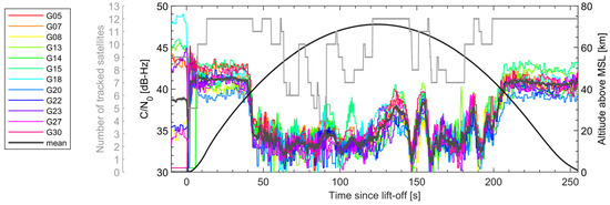
Figure 1.
ratios for the GPS signals tracked by the DLR Phoenix-HD GPS receiver on SOAR.
2.2. MAIUS-2 Mission
The MAIUS-2 (Materiewellen Interferometrie unter Schwerelosigkeit) sounding rocket was launched from Esrange on 2 December 2023. It was a two-stage rocket vehicle and reached an apogee altitude of 233 km. In contrast to SOAR, each motor stage was separated after burnout and the spin was stopped at the beginning of the experimental phase. The attitude of the payload was controlled and kept stationary throughout the flight until atmospheric re-entry. The payload was decelerated by parachute and recovered after landing. The payload was equipped with a wraparound antenna and an additional inertial navigation system. Figure 2 shows the ratios and the number of tracked satellites. The average ratio of 39 dB-Hz at the beginning of the flight was slightly worse than on SOAR. The reason for this was electromagnetic interference from the payload electronics and inadequate shielding of the antenna and receiver against interference on board. At T + 33.6 s, at an altitude of about 22.5 km, the average ratio dropped below the minimum threshold of 31 dB-Hz but increased again to values between 32 dB-Hz and 35 dB-Hz at higher altitudes. On the descent, the average ratio fell again below 32 dB-Hz and rose again afterwards. Contrary to SOAR, the receiver was indeed able to track the carrier and code of most of the signals during the coast phase but the signals were not properly bit- and frame-locked so that none of the signals could be used for computing the navigation solution after T + 33.6 s. During the re-entry, the payload did not spin stably like for SOAR due to the missing fins but was in a highly dynamic flat spin motion which hindered the reacquisition of the GPS signals even without jamming effects. The coarse trajectory was provided by the inertial navigation system instead.
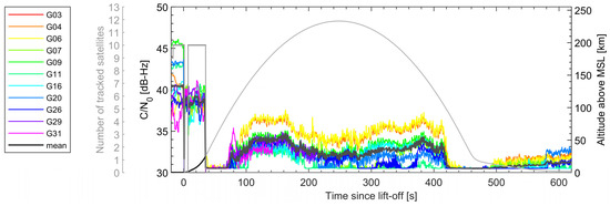
Figure 2.
ratios for the GPS signals tracked by the DLR Phoenix-HD receiver on MAIUS−2.
Figure 3 shows the power spectrum of the baseband signal, which was generated by the Novatel OEM719 receiver at different altitudes. The power spectrum covers the L1 frequency band between 1531 MHz and 1631 MHz. The black line represents the power spectrum shortly after lift-off at an altitude of 2 km. The blue line represents the power spectrum at an altitude of 30 km, and the red line illustrates the power spectrum near the apogee at an altitude of 233 km. For reference, the grey line shows the power spectrum that was recently recorded on board of a test aircraft on a flight over Finnmark at an altitude of about 13 km. The spectrum at 2 km is clean and shows no peculiarities. Only at 1575.42 MHz, where the navigation signals of several GNSS are centred, does the spectral density rise above the noise floor. Centred at 1562.098 MHz and at 1575.42 MHz, additional jamming signal power with a bandwidth of about 2 MHz and 3 MHz, respectively, becomes visible at altitudes of 30 km and 233 km. Furthermore, additional signal power is received between 1598 MHz and 1605 MHz. It is noticeable that the noise floor of the power spectrum at 30 km is roughly 5 dB above the noise floor of the power spectra at 2 km and 233 km. This is due to the automatic gain control (AGC), with which the GNSS receiver optimizes the analog signal level for the range of the analog to digital stage.
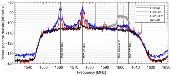
Figure 3.
Periodogram of the baseband signal recorded by the Novatel OEM719 on MAIUS−2.
The power spectrum of the jamming signal at 1562.098 MHz is at 30 km about 19 dB and at 233 km about 11 dB above the undisturbed noise floor at 2 km. Due to the flat profile of the power spectrum of the jamming signal at 1562.098 MHz, the jamming signal may be bandlimited white noise modulated on the carrier. The power spectrum of the jamming signal at 1575.42 MHz is at 30 km about 18 dB and at 233 km about 12 dB above the undisturbed noise floor at 2 km. The profile of the power spectrum is not as flat as at 1562.098 MHz, which suggests that the jamming signal is either not only pure bandlimited white noise or that there is another narrow band jammer superposed. Interestingly, the power spectra of the jamming signal between 1598 MHz and 1605 MHz at 30 km and at 233 km do not differ as much as for the two other jamming signals. The jamming primarily affects the GPS L1 C/A, GPS L1C, Galileo E1-B/C and BeiDou B1C signals centred at 1575.42 MHz, the BeiDou B1I signal centred at 1562.098 MHz and the GLONASS FDMA L1 C/A and CDMA L1OC signals between 1598.0625 MHz and 1605.375 MHz. The GPS M-Code and Galileo E1-A signals are not affected by the jamming. Apart from the jamming signal between 1598.0625 MHz and 1605.375 MHz, the power spectrum recorded on the aircraft fits very well to the spectra observed on MAIUS-2, even though the aircraft was much closer to the jammer.
Figure 4 combines all periodograms over the entire flight time in a spectrogram. The frequency is limited to the range between 1550 MHz and 1610 MHz to better recognize the jamming signals. The spectrogram illustrates that the jamming starts quite abruptly at T + 33.6 s at an altitude of 22.5 km and stops quite abruptly at T + 465.7 s. The jamming signal power is strongest when it appears and slightly decreases with increasing altitude. However, the jamming is still noticeable at the apogee at 233 km.
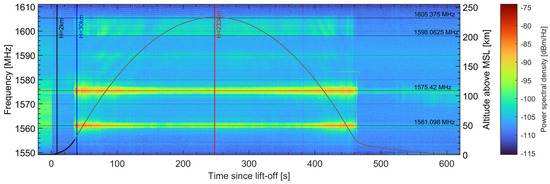
Figure 4.
Spectrogram of the baseband signal recorded by the Novatel OEM719 on MAIUS−2.
3. Rough Estimation of the Jammer Location
The location of the jammer can at least be roughly estimated from the different altitudes at which the jamming signal appeared during the ascent and disappeared during the descent of the various sounding rocket trajectories. In particular, the different altitudes at which the jamming appeared or disappeared during the flights of SOAR launched from ASC and MAIUS-2 launched from Esrange make it possible to geometrically analyze the origin of the jamming signal if the following assumptions are made:
- The jammer that affected the flight of the SOAR sounding rocket is the same jammer that affected the flight of the MAIUS-2 sounding rocket;
- The jammer had not moved between the flights of the SOAR sounding rocket on 13 November 2023 and the MAIUS-2 sounding rocket on 2 December 2023;
- There is only one jammer that is located somewhere on the ground;
- The Earth’s surface is modelled by the WGS84 ellipsoid, and the terrain is not considered;
- The lobe of the jamming signal, whose shape and orientation are unknown, is limited on the lower side by a minimum elevation angle, which can be positive, zero or even negative if the bending of the jamming signals by the troposphere is considered. Navigation signals in the L-band which are emitted horizontally with zero elevation are bended by the troposphere up to 0.5 deg.
The Earth’s ellipsoid is described by the function
with the matrix
where is the Cartesian position vector of a point on the ellipsoid, and and are the semi-major and semi-minor axes of the ellipsoid, respectively, as defined by WGS84. The minimum elevation mask can be described by a cone whose principal axis is perpendicular to the Earth’s ellipsoid and whose apex is at the location of the jammer on the Earth’s ellipsoid. The opening angle of the cone is with being the minimum elevation angle. The equation of the cone is given with
where is the Cartesian position vector of a point on the cone, is the Cartesian position vector of the jammer on the Earth’s ellipsoid and is the normal vector, which is the gradient vector of the Earth’s ellipsoid at ,
Using (1), (3) and (4), and assuming that the points of the sounding rocket flight paths marking the start and end of interference, , lie on the cone of the minimum elevation mask, a quadratic equation system consisting of equations can be set up.
The start and end points of the interference are identified from the ratios as well as the MAIUS-2 spectrogram. The quadratic equation system is solved for the unknown jammer location using MATLAB’s (https://www.mathworks.com/products/matlab.html) fminsearch function. The used cost function is . The minimum elevation angle is set to zero so that the cone of the minimum elevation mask degrades to a plane that is tangential to the Earth’s ellipsoid at the jammer location . Besides the jammer location , the jammer location error covariance is estimated. It considers an uncertainty of the minimum elevation angle of 0.5 deg (1σ) and uncertainties of the start and end points of the jamming signals of 1000 m (1σ) in horizontal direction and 2000 m (1σ) in vertical direction. The covariance is calculated from Monte-Carlo runs using 10,000 randomly chosen, Gaussian distributed elevation angle and position errors. Figure 5 and Figure 6 illustrate the result of the estimation of the rough location of the jammer from two viewing directions. The 95% uncertainty ellipse is computed from the covariance matrix .
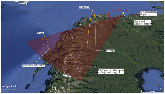
Figure 5.
Illustration of the estimated location of the jammer, the 95% uncertainty ellipse and the trajectories of the SOAR and MAIUS−2 sounding rockets. The transparent red surface represents the minimum elevation mask of the jamming signal. Since the elevation angle was chosen as zero, it is a plane that is tangent to the Earth’s ellipsoid at the jammer location .
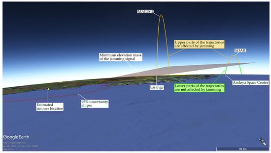
Figure 6.
Scene viewed from the northeast. The green parts of the trajectories that are below the elevation mask are not affected by the jamming signal; the orange parts, however, that are above the elevation mask are affected by the jamming signal.
4. Conclusions
On most sounding rockets launched from Esrange since the end of 2022, interference caused the DLR Phoenix-HD and Novatel OEM719 receivers to lose the navigation solution at some point during the ascent and only recover it after the parachutes were deployed. On the sounding rocket launched from ASC, however, interference indeed reduced the signal quality, but not enough to stop the GNSS receivers from computing a navigation solution. Geometric considerations made it possible to roughly localize the source of the interference signals from the points of the flight path marking the start and end of interference. For that, a minimum elevation mask of the interference signal lobe was assumed.
The ratios and power spectra which have been recorded on sounding rockets since the end of 2022 revealed the following:
- Interference can be observed at Esrange at an altitude above 22 km and at ASC at an altitude above 36 km and reaches even up to the apogee of the trajectory;
- The power of the interference signal is stronger at Esrange than at ASC and decreases the average ratio by 5–10 dB;
- Interference affects the GPS L1, Galileo E1 and BeiDou B1C and B1I frequencies as well as the GLONASS FDMA frequency band;
- The interference signals are probably bandlimited white noise on various carrier frequencies with a bandwidth of about 2 MHz, 3 MHz or 7 MHz;
- Interference seems to be permanently active.
The fact that the power of the interference signals exactly covers the three signals in the L1 band used by the different GNSS, the high power of the interference signals, the long duration of the interference for more than one year and the reporting of interference by airliners in large areas of northern Europe are strong indications that the interference is most likely intentional jamming and not unintentional, for example, due to a misfunction of a terrestrial transmitter.
It is expected that the jamming will be indefinitely active in northern Scandinavia in the future. It will therefore be necessary to adapt the current navigation system of the sounding rockets to the new conditions. On future sounding rocket missions, the jamming signal shall be analyzed in more detailed. This includes the modulation of the jamming signal and the interference of the navigation signals in the L2- and L5-bands. Furthermore, even greater efforts will be required to reduce on-board interference to improve the GNSS signal quality by default and thus increasing receiver robustness against external interference.
To make GNSS more robust for future sounding rocket flights, work has begun on controlled reception pattern antennas (CRPAs) for sounding rockets that are capable of nulling the jamming signals. For example, [7] describes how a GNSS CRPA was successfully applied to detect, localize and isolate radio frequency interference. Furthermore, it is intended to use DLR’s GALANT receiver which is able to additionally form reception beams to the single GNSS satellites. Alternatively, the installation of a local triangulation system is being considered, consisting of three base stations distributed on the ground on the rocket range and a transponder on board the sounding rocket. By using proprietary ranging signals with frequencies other than GNSS, the navigation system is most likely more robust against jamming.
The flight guidance and range safety of future micro launch vehicles to be launched from the new spaceports in Sweden and Norway may be affected by the observed GNSS jamming if their navigation systems overly rely on the availability and quality of a GNSS navigation solution. Manufacturers and operators should be aware of the possible presence of intentional GNSS jamming in northern Scandinavia and the risk of losing or degrading the GNSS navigation solution during parts of the critical guided flight phase.
Author Contributions
Conceptualization, B.B., M.H.-E., R.K. and O.M.; experimentation, B.B., M.M. and M.H.-E.; data post-processing, B.B. and O.M.; visualization, B.B.; writing—original draft preparation, B.B.; writing—review and editing, O.M., M.H.-E. and R.K.; project administration, M.H.-E. and R.K.; funding acquisition, R.K.; supervision, R.K. All authors have read and agreed to the published version of the manuscript.
Funding
This research received no external funding.
Institutional Review Board Statement
Not applicable.
Informed Consent Statement
Not applicable.
Data Availability Statement
The raw data supporting the conclusions of this article cannot be made available by the authors. This is due to legal restrictions imposed by the use of GNSS on sounding rockets flying faster than 600 m/s, amongst others.
Acknowledgments
The authors would like to thank the MORABA team for the accommodation of the GNSS receiver experiment on the sounding rockets MAIUS-2 and MAPHEUS-14 on short notice and for their support during the campaigns.
Conflicts of Interest
The authors declare no conflicts of interest.
References
- Montenbruck, O.; Markgraf, M. Global Positioning System Sensor with Instantaneous-Impact-Point Prediction for Sounding Rockets. J. Spacecr. Rocket. 2004, 41, 644–650. [Google Scholar] [CrossRef]
- Pullen, S. GNSS Spoofing and Jamming in Eastern Europe. Inside GNSS. Available online: https://insidegnss.com/gnss-spoofing-and-jamming-in-eastern-europe/ (accessed on 27 April 2024).
- Nilsen, T. GPS Jamming Came from Kola, Defense Ministry in Norway Confirms. Available online: https://thebarentsobserver.com/en/security/2018/11/gps-jamming-came-kola-defense-ministry-norway-confirms (accessed on 27 April 2024).
- Nilsen, T. Russian Military Officials Arrive in Oslo as Norway Puts GPS Jamming Facts on the Table. Available online: https://thebarentsobserver.com/en/security/2019/03/russian-military-officials-arrive-oslo-norway-provides-facts-gps-jamming (accessed on 27 April 2024).
- Nilsen, T. More Russian GPS Jamming than Ever Across Border to Norway. Available online: https://thebarentsobserver.com/en/security/2022/07/more-russian-gps-jamming-ever-across-border-norway (accessed on 27 April 2024).
- Nilsen, T. Russian Jamming Is Now Messing Up GPS Signals for Norwegian Aviation Practically Every Day. Available online: https://thebarentsobserver.com/en/security/2024/02/russian-jamming-now-messing-gps-signals-norwegian-aviation-practically-every-day (accessed on 27 April 2024).
- Berz, G.; Barret, P.; Disselkoen, B.; Richard, M.; Bleeker, O.; Rocchia, V.; Jacolot, F.; Bigham, T. Interference Localization using a Controlled Radiation Pattern Antenna (CRPA). In Proceedings of the 29th International Technical Meeting of the Satellite Division of the Institute of Navigation (ION GNSS+ 2016), Portland, OR, USA, 12–16 September 2016; pp. 3053–3062. [Google Scholar] [CrossRef]
Disclaimer/Publisher’s Note: The statements, opinions and data contained in all publications are solely those of the individual author(s) and contributor(s) and not of MDPI and/or the editor(s). MDPI and/or the editor(s) disclaim responsibility for any injury to people or property resulting from any ideas, methods, instructions or products referred to in the content. |
© 2025 by the authors. Licensee MDPI, Basel, Switzerland. This article is an open access article distributed under the terms and conditions of the Creative Commons Attribution (CC BY) license (https://creativecommons.org/licenses/by/4.0/).