1. Introduction
Impulse Radio Ultra-Wide Band (IR-UWB) Real-Time Localization Systems (RTLSs) usually require high position-fix rates and, therefore, cannot rely on the conventional but slow two-way ranging (TWR) approach. Some RTLSs utilize the Time (Difference) of Arrival (ToA or TDoA) positioning in order to achieve hundreds or thousands of positioning fixes per second [
1].
In general, there is a fixed infrastructure of the system—anchors and the localized equipment—tags. Each tag or anchor uses an on-board free-running oscillator as a frequency reference of the UWB transceiver chip; usually, reasonably priced crystals or TCXOs are utilized. The IR-UWB positioning methods rely on precise timestamping; the resolution of the timestamps is 15.65 ps, i.e., 1/128 of the mandatory 499.2 MHz chipping rate [
2]. It is worth noting that the standard deviation of the timestamp is approximately 150 ps for the DecaWave/Qorvo DW1000 modules used in this research.
Both the transmission and reception timestamps are referenced to the local timebase of the UWB transceiver. In order to be able to utilize a ToA, TDoA, or similar positioning approach, it is necessary to address the necessity of a common timescale for the measurements at the anchors.
Therefore, such localization systems require either precise and robust synchronization of the anchor transceivers or the use of one of the “synchronization-free” methods.
Multiple approaches can be used for synchronization of the UWB transceivers (e.g., linear interpolation, proportional–integral–derivative (PID) controller loop, etc.); however, the Kalman filter (KF) offers a better performance and clock offset variance estimate [
3]. Generally, no clock steering is applied, and the clock state (offset, drift, and drift rate) is estimated. Extrapolated correction is then applied to the collected timestamps.
For instance, a linear interpolation is utilized in [
4,
5]; the former evaluates the method using three different clock sources. Filtering of anchor clock offsets obtained from anchor-to-anchor ranging is described in [
6]. A constant clock offset is assumed in [
7]. The positioning method in [
8] relies on the reset of the anchor timebases that are triggered by a periodic synchronization message from a master anchor. The KF-based algorithm developed in our previous work [
9] is able to deal with unstable oscillator drifts during the warm-up period and has been used in various ToA [
10] and TDoA scenarios [
11,
12]. The clock bias and drift are estimated and used for measurement correction in [
13,
14], although a Kalman filter is not used. Moreover, the Chorus system [
14] transmits the messages from anchors almost concurrently, and a great emphasis is put on short transmission delays in order to minimize the drift-related errors.
The “synchronization-free” examples generally relay the messages in anchors as quickly as possible in order to minimize the effects of drifting local clocks. This is the case of the Sequential-TDoA approach [
15], where each transmission from the anchor triggers almost immediate transmission from another anchor. A similar principle is adopted in [
16]; however, the whole sequence of messages is initiated by transmission from the tag.
Nevertheless, for all the mentioned positioning systems, the stability of the reference clocks is important, either as one of the determining factors for positioning accuracy or as an algorithm tuning parameter. In particular, the accuracy of systems that rely on consistent clock behavior over a reasonably long time interval, e.g., [
7,
8,
14,
15,
16], is heavily dependent on the clock performance.
An initial investigation of the characteristics of measurements provided by the DWM 1000 transceiver was presented in [
17]; the stability evaluation results based on the timestamps and two estimates of carrier-frequency offset (CFO) were presented. Nonetheless, only two identical modules were tested.
In this paper, we would like to focus on the most accurate timestamp-based evaluation of the UWB transceiver clock stability. Moreover, two of the measurement transceivers feature frequency reference derived from a Caesium clock. Therefore, it is possible to discover which of the clock errors are attributed to the UWB transceivers.
An intuitive transceiver clock simulation approach is presented as well. The simulation is an effective tool to evaluate and tune the synchronization or positioning algorithms without the need of hardware-pulling of the UWB reference oscillators. It also allows testing of the algorithms with defined and repeatable scenarios, potentially featuring extreme clock states, possibly beyond the specified operational envelope.
This paper is organized as follows:
Section 2 and
Section 3 present the stability measurement methods and their results, respectively.
Section 4 is devoted to the clock simulation, and a summary of the paper is provided in
Section 5.
2. Transceiver Clock Stability Measurement
In this research, we have used Decawave/Qorvo DW1000 UWB transceivers. Their internal clocks are derived from an external 38.4 MHz frequency reference. Two phase-locked loops (PLLs) are utilized: one is for the RF circuitry, and one is for the digital part of the transceiver [
18]. It is not possible to observe the internal signals directly; therefore, we exploit the messages sent between several transceivers to observe the relative clock states.
The more accurate option is a collection of the message transmission timestamp (in the transmitter timescale) and the reception timestamp (in the receiver timescale) and computing the integrated time error [
17].
The alternatives are an observation of the carrier-frequency offset (CFO), which is proportional to the fractional-frequency error. However, CFO measurements suffer from a substantial amount of white frequency modulation (WFM) noise; moreover, they are biased [
17]. Consequently, the former timestamp was used.
2.1. Devices and Data Collection
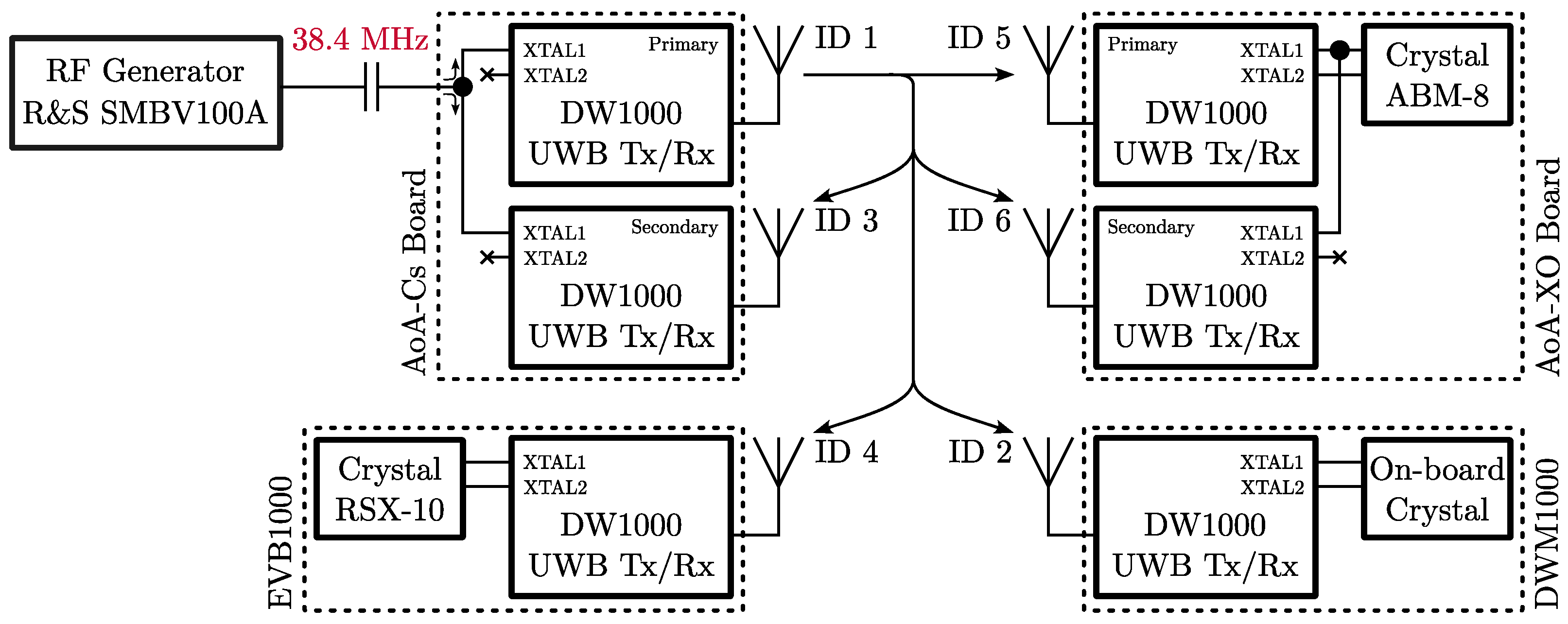
During the clock stability test, we used six transceivers: two UWB-AoA boards in dual-transceiver configuration (with DW1000 transceivers), one IDOL anchor with a single DWM1000 module, and one Decawave EVB1000 evaluation board with a DW1000 transceiver. The devices and their respective clock sources are summarized in
Figure 1.
The first AoA board referenced to the Caesium standard will be further denoted as
AoA-Cs. On the AoA board, there are two DW1000 transceivers that are referenced to a common frequency source; the details of the design and the evaluation of the board are available in [
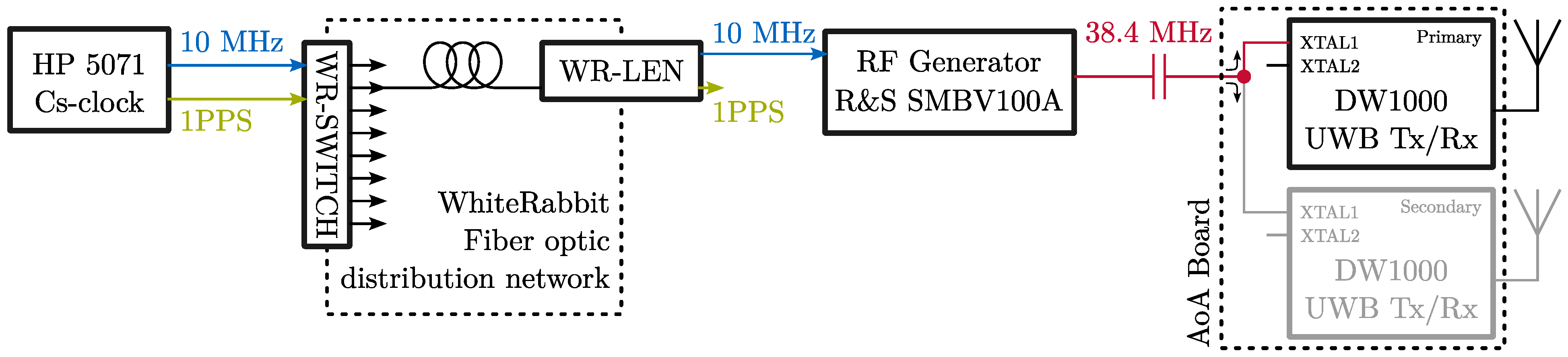
19]. In the case of AoA-Cs, the reference frequency is derived from a primary standard, according to the block diagram in
Figure 2. The 10 MHz and 1PPS outputs from the HP/Microsemi 5071A Caesium frequency standard are distributed via the White Rabbit (WR) optical timing network. The 10 MHz output from the WR-LEN terminal device is then used to discipline the RF generator (R&S SMBV100A) that provides the stable 38.4 MHz reference to the AoA board. The primary AoA-Cs transceiver is assigned number 1, and the secondary is assigned number 3.
The second AoA board is referenced as AoA-XO. The hardware is identical to the AoA-Cs, except the frequency reference. The primary AoA-XO transceiver drives a crystal resonator Abracon ABM8-38.400MHZ-10-B1U-T, which is connected to the XTAL1 and XTAL2 pins. The secondary AoA-XO transceiver uses this crystal as well; only the XTAL1 pin is connected, i.e., the external reference mode is utilized. The crystal should feature 10 ppm accuracy and 10 ppm stability; however, its performance may be sub-optimal due the loading caused by the connection of the secondary transceiver. The primary AoA-XO transceiver is assigned number 5, and the secondary is assigned number 6.
The IDOL Anchor features a DWM1000 module with an internal, on-board crystal as a frequency reference. The datasheet specifies ±30 ppm frequency stability with temperature variations [
20]. Number 2 is assigned to the DWM1000 transceiver.
The evaluation board Decawave EVB1000 uses a Rakon RSX-10 crystal as a frequency reference for the DW1000 transceiver. Unfortunately, a detailed crystal description is unavailable. The EVB1000 is marked as number 4.
Messages containing the transmission timestamp are broadcasted from the AoA-Cs primary transceiver (device 1). All other devices receive and timestamp each of the messages. The repetition period of the messages was 50 ms, and the whole test duration was approximately 65 min; approximately 80,000 epochs were collected.
2.2. Data Processing
The processing begins with a conversion of the reception and transmission timestamp pairs to an integrated time error
. At each epoch
i, it holds
where
and
denote the reception and transmission timestamps, where the subscripts denote the epoch index.
Due to the nature of radio communication, we had to deal with missing messages; the worst lost message rate of 0.86% has been observed in the IDOL Anchor device. The missing epochs were linearly interpolated; according to [
21], the impact on the stability evaluation results is negligible.
The integrated time error was also converted to the fractional-frequency error
by a simple differentiation
The stability of the clock observation has been evaluated by means of the modified Allan variance (MVAR), which is usually plotted as its square root, i.e., modified Allan deviation (MDEV). It is practical to compute MVAR from the integrated time error (
) series:
The averaging interval
is the integer
m-multiple of the sampling period
.
The key advantage of the MVAR over the overlapping Allan variance (AVAR) is the ability to distinguish flicker phase modulation (FPM) noise and white phase modulation (WPM) noise [
21]. It is also advantageous to evaluate the time Allan variance according to
The noise type has been identified by the Lag-1 method [
22], which provides a dominant power-law noise type depending on the
value. In the Results section, we will distinguish the following noise types: white phase modulation (WPM), flicker PM (FPM), white frequency modulation (WFM), flicker FM (FFM), random walk FM (RWFM), and flicker walk FM (FWFM).
3. Transceiver Clock Stability Results
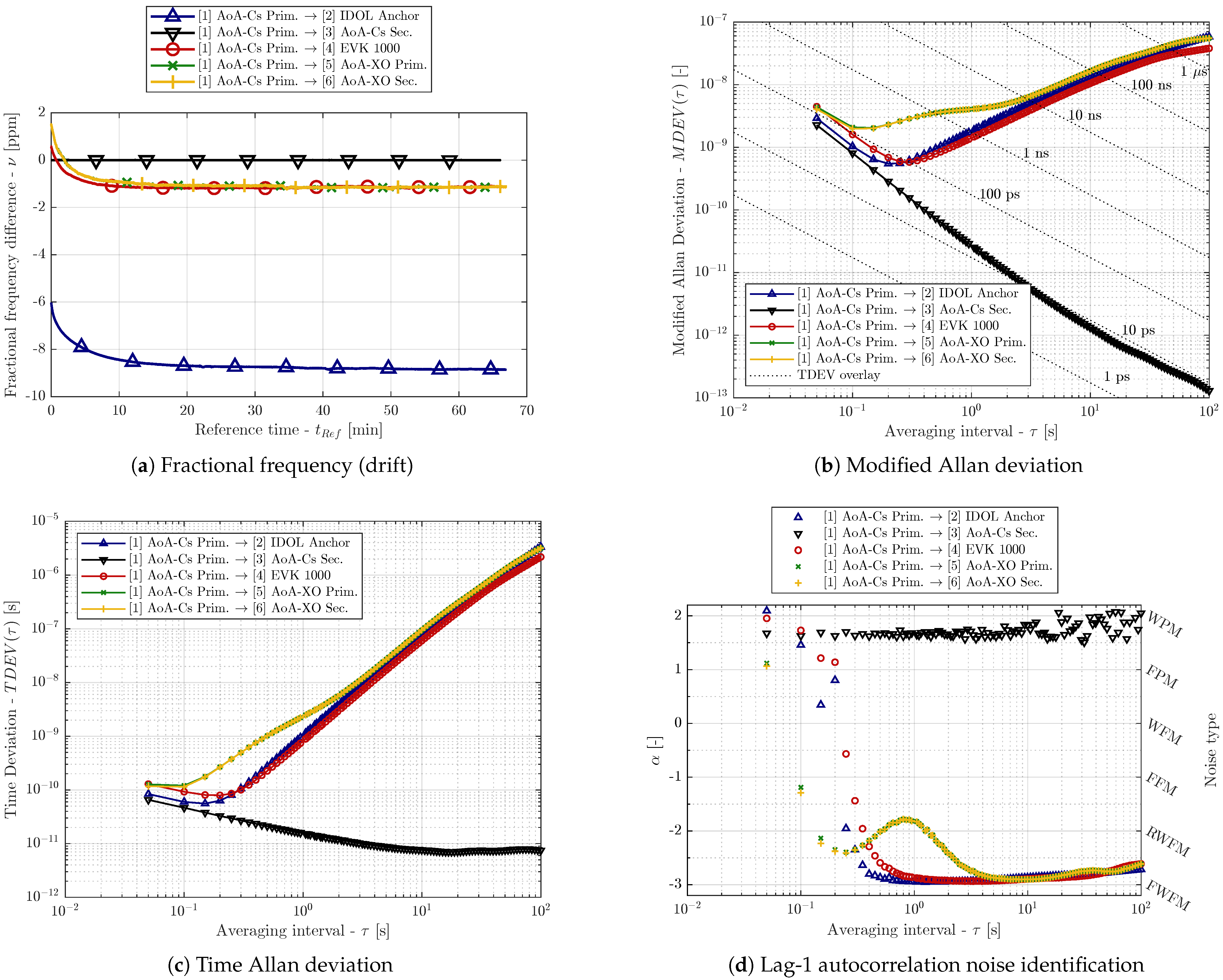
The results of the stability analysis based on the whole dataset are provided in
Figure 3. From the fractional frequency difference (clock drift) plot (
Figure 3a), it is obvious that no drift is present for device 3 (black), which shares the Caesium-derived reference with device 1. All other clocks suffer from clock drift. Moreover, the clock drift is changing in the first minutes of the test, when the transceivers and the crystals were warming up; an exponential-decay shape can be observed in the time series. Clearly, the stability results are affected by this phenomenon; however, similar behavior is encountered in non-laboratory UWB RTLS installations as well.
Figure 3b provides modified Allan deviation (MDEV) results in a
-
plot, and
Figure 3c presents the results in the time Allan deviation (TDEV) form. Obviously, the transceivers with the Cs-derived reference have exceptional long-term (large
) stability and suffer only from the phase modulation noise. Additionally, the lag-1 autocorrelation noise type identification (see
Figure 3d) confirms that only the WPM noise is present for device 3. The WPM can be attributed to the finite accuracy of the timestamping.
For the other devices, the minimum MDEV and minimum TDEV are observed for
between 0.1 s and 0.5 s. The WPM noise component is present in timestamps from all devices, although with different magnitudes; the behavior differs for the higher
values. Higher-order frequency modulation noise (RWFM or FWFM) is observed for devices 2 (IDOL Anchor), 4 (EVK1000), 5, and 6 (AoA-XO). Moreover, transceivers 5 and 6 both suffer from anomalous noise dominant for
from 0.5 s to 2 s; the lag-1 method suggests a flicker FM character of the noise. It is possible that such a non-typical characteristic is caused by the parasitic crystal loading on the AoA-XO board (see
Section 2). Nonetheless, the behavior is consistent for both transceivers on the AoA-XO board.
The long-term noise of devices 2, 4, 5, and 6 is characterized by the lag-1 method as FWFM, see
Figure 3d. However, this classification cannot be considered reliable due to the temperature-induced drifts. Therefore, identical analysis has been performed for the dataset without its first 30 min, i.e., the devices should not suffer from the warm-up-related clock drift. The MDEV and noise identification results for the cropped dataset are provided in
Figure 4a and
Figure 4b, respectively. Whilst the short-term stability (WPM region) remains almost identical, the long-term stability results are naturally improved. The magnitude of the higher-order noise is generally lower; thus, the minimum of both MDEV and TDEV is lower and shifted to slightly higher
values (
Figure 4a). Also, the noise character shifts towards RWFM for the
values above 0.5 s.
It can be observed that the short-term stability (in the WPM region) differs between the devices. The best short-term performance is achieved by device 3, which features an RF generator as a reference. The phase noise performance of the crystals used in other devices is worse than the one of the devices referenced to the Cs-disciplined RF generator, and thus the timestamping noise (i.e., WPM noise) is more powerful. The room for performance improvement in the short-term region is rather limited. Improvement beyond the performance observed for device 3 with spectrally clean frequency reference would be extremely costly and impractical for non-laboratory UWB RTLS systems.
On the other hand, significant improvements are possible in the long-term stability. More stable reference (either crystal resonator or oscillator) would move the minimum MDEV and TDEV to lower averaging intervals , which would allow a longer synchronization message period for the synchronized RTLS anchors or would suppress the errors caused by the retranslation delays for the “synchronization-free” methods. It would be also beneficial to utilize temperature-compensated crystal oscillators (TCXOs) instead of providing uncompensated crystal resonator to the DWM1000 chip. This would lead to a reduction in the instability induced by thermal changes. The performance achieved by device 3 is far beyond what is necessary for practical realizations of UWB RTLS systems. The results also suggest that, in such cases, the thermal stability may be more important than the steady-state stability of the frequency reference.
4. UWB Transceiver Clock Simulation
The purpose of the UWB clock simulation is to enable an evaluation of the timestamp-based methods and algorithms under known and repeatable conditions, or even conditions difficult to achieve in actual measurement, e.g., extreme oscillator drifts. The simulation combines a deterministic and stochastic element. The former covers the exponential drift, which is typically observed during the warm-up phase [
4,
9], and initial conditions. The stochastic part generates the power-law noise components. The exponential decay of the clock drift is defined in terms of fractional frequency deviation
:
Constants
and
define the desired initial and the asymptotic clock drift values, and
is the time constant of the exponential decay. All three values are parameters of the simulation. However, the simulation is based on the clock drift rate time series and thus
The block diagram of the simulation is available in
Figure 5. The process starts with the generation of the deterministic component of the clock drift rate
. Scaled white noise is then added to simulate RWFM noise and scaled pink noise to create the FWFM component. The noisy clock drift rate is denoted by
, see (
7). By means of the integration and addition of properly scaled flicker (pink or
) noise
and white (Gaussian) noise
, the FFM and WFM noise components are simulated, and a noisy clock drift series is created
as described in (
8). A similar approach is used in (
9) to simulate the clock offset error
, including the WPM and FPM noise, i.e., the deviation from the ideal clock.
Coefficients
,
, …,
denote the scaling factors for scaling the white and pink (flicker) noise. Symbols
and
are the initial conditions of the clock drift and clock offset deterministic component. It is worth mentioning that the deterministic function
is not limited to the exponential—any differentiable function can be used. A similar approach for generating power-law noise components has been used in [
23]; nonetheless, the deterministic part of the simulation is not included.
The simulation is performed in the Matlab software; naturally, the discrete-time analogy is implemented. The integrals are realized by means of the cumulative sum, and functions randn and pinknoise are utilized for white and flicker noise generation.
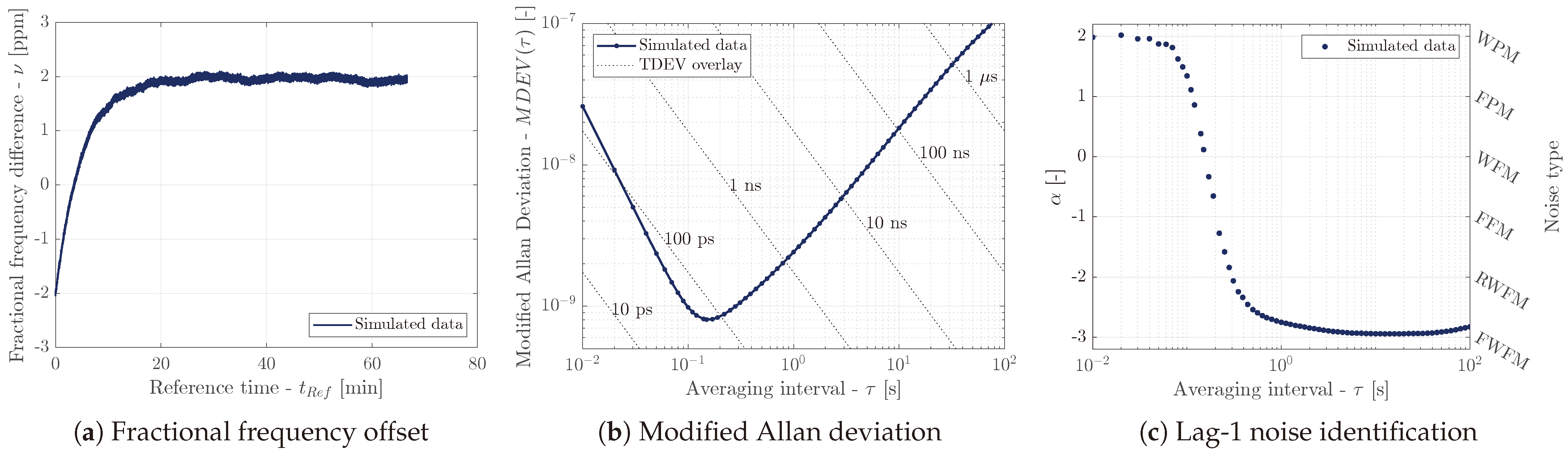
A demonstration of the simulation is available in
Figure 6. The simulated clock drift
that is decaying from
towards
with time constant
is clearly visible in
Figure 6a. The RWFM and WPM noises were simulated in this particular example.
Figure 6b presents MDEV for the simulated data, which resembles the results for the real transceivers. The noise characterization (
Figure 6c) confirms the WPM character of the noise for averaging intervals
. For
, the FWFM character was observed due to the deterministic exponential component. It is acknowledged that RWFM noise was identified correctly when the deterministic part of the simulation was omitted.
5. Conclusions
The performance of several UWB transceiver clocks has been evaluated with respect to the transceiver referenced to the RF generator disciplined by a Caesium primary frequency standard. The long-term stability of the transceiver clock is determined by the reference frequency source performance. A substantial contributing factor is the thermal instability of the crystal resonators; therefore, the use of TCXOs can be recommended for applications, where stability for intervals above 100 ms matters.
The short-term stability is determined by the transceiver timestamping accuracy. The timestamping noise has a WPM character, and it changes slightly depending on the frequency reference used. Most likely, the phase noise characteristics of the frequency reference is a contributing factor; however, the space for improvement is rather limited. The results obtained with the Cs-disciplined RF generator as a frequency reference are likely at the limit of the performance achievable with the DW1000 transceiver.
In the last section, a simulation algorithm of the UWB transceiver clock errors was presented. An example of its results has been provided.


