Abstract
This paper deals with the concept of a GNSS monitoring network, which fulfills requirements in relation to sustainability, cost efficiency and flexibility. For the proposed approach, the hardware of the GNSS monitoring stations should be reduced to a minimum. Therefore, Remote Radio Head sensors or especially RF Front-Ends, which are already used in the field of GNSS, should be used. In this concept, GNSS network stations are equipped with an antenna, an RF Front-End, and hardware for data transfer (raw I&Q samples) to a central processing facility. The idea is to realize a collaborative processing of all receivers with a Multi-Receiver-Vector Tracking (MRVT) algorithm in one single Software-Defined GNSS receiver (SDR).
1. Introduction
Nowadays, Global Navigation Satellite Systems (GNSS) are a widely used technology for navigation, positioning and timing. This technology is an important part of today’s infrastructure and economy. Such systems have developed rapidly in the last two decades. The number of available satellites increased rapidly and the signals from those satellites are getting better and better. Due to the increasing number of applications and their high requirements, it is becoming more and more important that existing algorithms and methods are constantly developed for future challenges and requirements. That is exactly what this paper aims to do. This paper presents a new innovative concept of building a sustainable, cost-effective, and flexible GNSS monitoring network.
GNSS networks have become increasingly important over the past 15 years. Not only for the provision of DGNSS or RTK data but also e.g., for orbit determination or interference monitoring. Current GNSS networks are based on a multitude of expensive ground stations. Such stations are equipped with a high-end antenna and receiver as well as fast data networks and central computer resources. The adaptation of these stations for new signals and services is usually associated with high costs and effort.
A new innovative approach is to build such GNSS monitoring networks with so-called Remote Radio Head (RRH) sensors.
In [1], Remote Radio Head is described as a small, outdoor module, which performs initial steps of signal processing. It is a widely used technology in wireless communication such as GSM or LTE for example. The tasks of such modules are the reception/transmission of analog/digital signals, filtering, amplification, and up/down conversion for the next processing steps. In the case of receiving analog signals, the last step of such module is the analog-digital conversion. The digital Intermediate Frequency (IF) signal can be processed in a remote processing facility.
RF Front-Ends are already used in the field of GNSS to digitize the satellite signal. With the digital IF signal from the RF Front-End, it is possible to realize many parts of a GNSS receiver in software. Hence, they are called Software-Defined GNSS receivers. Due to the fact that SDRs have many advantages in comparison to hardware receivers, the market has been rapidly growing in the last years. In comparison to hardware receivers, this approach is flexible toward new signals and services. The modification of such receivers can be realized by software updates via remote access, and it is not necessary to change hardware components. It depends on the application but in general, SDRs are cheaper than hardware receivers. To run such an SDR, the following parts are necessary:
- GNSS antenna;
- RF Front-End;
- Suitable Software for processing the digital output of the RF Front-End.
The general design of a GNSS receiver can be divided into four parts and is shown in Figure 1.
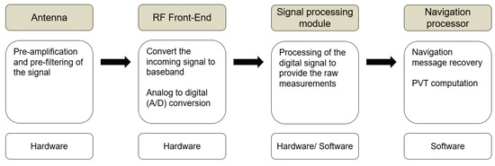
Figure 1.
General design of a GNSS receiver.
In the proposed concept of a collaborative processing of multiple receivers in a GNSS monitoring network, the signal processing module especially the satellite tracking is a key component. Therefore, only the tracking part will be discussed in more detail, other processing parts (e.g., acquisition, data processing) will not be covered in this paper. There exist different algorithms for tracking GNSS satellites. Some algorithms process the different channels independently and others process them with dependencies. The next chapter presents three different methods to track GNSS satellites. The last one is called Multi-Receiver-Vector Tracking, which is planned to be implemented for a collaborative processing of all stations within the monitoring network. In [2,3] a possible formulation of the MRVT algorithm is presented.
2. Materials and Methods
2.1. Materials
For software development and first investigations of advanced receiver tracking methods, the used data (I&Q samples) was simulated with a GNSS signal simulator from OHB Digital Solution [4]. Therefore, the GPS L1 C/A and the Galileo E1B signal were simulated and generated with a sampling frequency of 14 MHz. The software was implemented in Python 3.9 and based on an open source Matlab SDR [5].
2.2. Methods
The first tracking method, which is presented in this paper, is the so-called scalar tracking. This processing method is the simplest form of tracking GNSS signals in a receiver. The channels work independently of each other and do not share information with each other. The next flowchart shows the general simplified design of a scalar tracking loop:
As can be seen in Figure 2, the output of the tracking channels (e.g., pseudoranges and pseudorange rates) goes directly to the navigation processor to compute the Position-Velocity-Time (PVT) solution of the receiver. There is no feedback link from the navigation processor to the tracking channels. Tracking and positioning are two clearly separate algorithms.
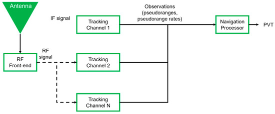
Figure 2.
General principle of scalar tracking.
The next tracking algorithm is called Vector Tracking (VT). In [6] (p. 438), Vector tracking is described as one of the most advanced signal processing methods and was proposed in 1980. In [7,8,9] the general design of vector tracking and the better performance relating to scalar tracking was investigated. In comparison to a conventional navigation processor, a Kalman Filter, respectively an Extended Kalman Filter is implemented and integrated in the tracking loop (see Figure 3). The Kalman Filter creates a feedback link between the PVT computation and each tracking channel. Therefore, the two steps (i.e., tracking and positioning) are combined into one algorithm. In [9] (pp. 391–396) two different formulations of this algorithm are described: the position-state formulation and the pseudorange-state formulation. In our concept, the first one is used. VT has a lot of advantages instead of using the scalar tracking algorithm.
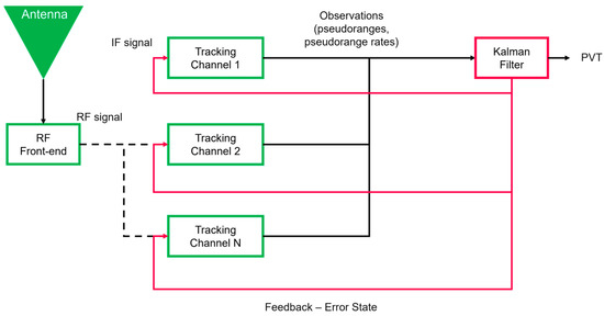
Figure 3.
General principle of vector tracking.
The Kalman Filter predicts the state vector (i.e., position, velocity, clock bias and clock drift) for the next epoch with a dynamic model, which can be static or kinematic. This makes the tracking more robust against unintentional and intentional interference e.g., jamming attacks. With this advanced tracking method, it is possible to track satellites with a lower Carrier-to-Noise Ratio (CNR).
A further advantage is that short signal outages, which occur in a GNSS denied environment e.g., in a tunnel, can be compensated due to prediction. Another common method for robust and reliable positioning is sensor fusion with inertial measurement units. Further, a GNSS/INS deep coupling method can improve the signal processing of the vector tracking algorithm at signal level in the GNSS receiver too.
The processing load and the complexity of a vector tracking loop are disadvantages. This could be challenging in real time applications. In addition to that, also a failure of one channel influences all other channels. The schematic flow of this tracking method is presented in Figure 3.
Vector tracking which combines multiple receivers is called Multi-Receiver-Vector Tracking (MRVT). In [2,3] the proposed algorithm was investigated and tested in different scenarios.
This algorithm is suitable for a collaborative processing of multiple GNSS receivers in one algorithm. It is planned to use one single Extended Kalman Filter to compute all PVT solutions from all stations. With this approach, the GNSS network geometry can be used as an additional information in the Kalman Filter. The baseline vector between two stations can be modelled as pseudo-observations since it is a rigid body. These observations produce a correlation between the receivers in the whole network and brings a decisive advantage in the collaborative processing. In Figure 4, the general principle of an MRVT algorithm can be seen:
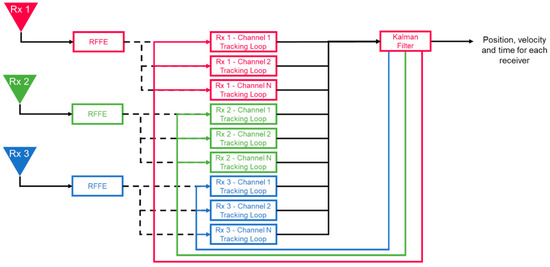
Figure 4.
General principle of Multi-Receiver-Vector Tracking.
3. GNSS Monitoring Network—Concept
The overall goal of this research is to develop a software-defined GNSS receiver, which can process raw I&Q samples from GPS and Galileo satellites of multiple receivers in one single algorithm. Therefore, one of the most advanced receiver tracking methods is used. The so-called Multi-Receiver-Vector Tracking algorithm, which is described in Section 2.2 in more detail. The basic idea is to build a GNSS monitoring network where the hardware is reduced to a minimum. In this concept, each GNSS network station is equipped with an antenna, an RF Front-End (RRH module), and a link for data transfer (cf. Figure 5).
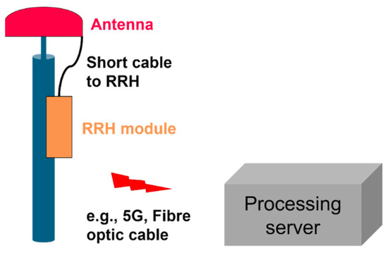
Figure 5.
Components of GNSS station in the monitoring network.
The analog GNSS signal is directly converted after the antenna to digital I&Q samples (RRH module). In the field of GNSS, this is realized by an RF Front-End e.g., HackRF One or BladeRF. Due to the fact that the signal is digitized near to the antenna, the transmission losses due to the cable are reduced to a minimum. The digital signal will be transferred to a central processing facility (Server), which performs the GNSS processing to get all PVT solutions from all GNSS stations. The data link between the RRH module and the central processing facility can be realized by 5G or fiber optic cable for example.
The overall concept of the proposed GNSS monitoring network can be seen in the following Figure 6:
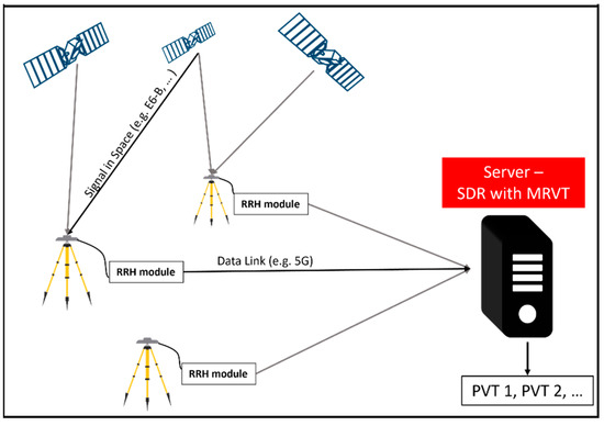
Figure 6.
Concept of a GNSS monitoring network with Remote Radio Head modules.
3.1. Advantages and Disadvantages
The main advantage of using a single Kalman Filter for all stations is that additional information can be used for signal processing. Especially the geometry of the GNSS network can bring a decisive advantage in relation to the accuracy, robustness, and applications of a GNSS monitoring network. Therefore, conditions in the Kalman Filter are introduced in form of “pseudo-observations” as three additional rows in the design matrix H (only two receivers). There exist different filter designs, which can be used in this application. The state vector includes the position, velocity, two clock errors and a clock drift of the receivers. A linear model realizes the prediction of the state vector of the next epoch. The considered design for the design matrix
and for both receivers
and are 0 or 1, depending on whether it is a GPS or Galileo observation. is set to 1 for pseudorange rate observations. , and are the derivations according to the position and velocity of the observation equations. The three additional rows for , and produce a correlation between the two stations. The final design matrix can be seen in Equation (3)
With those additional rows, the geometry of receiver 1 and receiver 2 can be modelled in the Kalman filter. In a GNSS monitoring network, the coordinates of the stations are well known. Therefore , and are introduced as accurate (pseudo) observations in comparison to the measured observations (i.e., pseudoranges and pseudorange rates).
A further big advantage is the flexibility due to new signals and services. Once the station is built up at a suitable place, the modification of these stations can be performed by software updates. Due to the fact that it is more cost effective than traditional GNSS networks, it is feasible to generate a GNSS network with a higher density and shorter baselines.
A challenge in the whole concept could be the huge amount of data, which must be transferred to the processing server. The recording of a GNSS signal (I&Q samples) with a sampling frequency of 40 MHz and an 8-bit quantization generates data of about 640 Mbit per second for example. A second challenge could be the time synchronisation between the stations. Due to the fact that all stations should be processed in one single Kalman Filter, the signals must be synchronized.
3.2. Applications
To operate such a cost-effective and flexible GNSS monitoring network opens many applications in the field of GNSS.
With such a monitoring network, it is possible to perform a kind of error detection of satellites and alert the user if errors in the satellite orbits occur. Due to the known coordinates and network geometry, it is possible to investigate the satellite orbits. A second application or research area is the observation of atmospheric effects for better weather forecasts for example. This includes the analysis of the ionosphere and troposphere in the area of the monitoring network. Due to rapidly increasing interference attacks, it is becoming more and more important to monitor such events. The GNSS monitoring network with RRH sensors can be used to detect and localize jammer or spoofer around the network. This would be of great importance in areas with critical infrastructure like airports. Because the hardware is reduced to a minimum, this concept is suitable for low energy PNT concepts especially in applications where energy is a critical factor. Hence, this concept is sustainable and future-proof for new applications.
4. First Results
In this chapter, first results of the software development are shown and discussed in more detail. The overall goal is to create a software, which performs a Multi-Receiver-Vector Tracking algorithm with GPS and Galileo observations. Especially GPS L1 C/A and Galileo E1B signals. In the first step, a vector tracking algorithm of a single static receiver with both constellations was implemented in the software. The result, in comparison to the scalar tracking method, can be seen in Figure 7 and Figure 8. In Table 1, statistical parameters are listed.
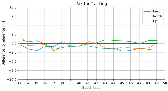
Figure 7.
Processing of GPS and Galileo observations with Vector Tracking.
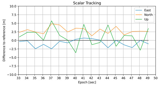
Figure 8.
Processing of GPS and Galileo observations with Scalar Tracking.

Table 1.
Statistical parameters of position solutions with simulated data.
In Table 1, the mean deviation of all position solutions to the reference position differs between the two tracking methods is shown. Vector tracking delivers better results than scalar tracking. This can also be seen in the standard deviation. Due to the Kalman Filter, vector tracking generates a smoother time series of position solutions than the standard tracking procedure does. To evaluate the filter, the dynamic model was set as kinematic with very low receiver motion. First investigations show that the initial state vector and the filter parameters of the Kalman Filter have a big influence on the results. To find the right parameters for this concept, the settings will be further investigated.
As it can be seen in Figure 7 and Figure 8, the positioning solutions, which are processed with vector tracking are slightly better than the traditional tracking method. One reason for that is the Kalman Filter. Vector tracking uses, beside the measurements, a dynamic model, to predict the state vector of the new epoch and combines the prediction and the measurements optimally and provides a Line-of-sight feedback from the PVT to the tracking part. The result of such mathematical operation are smoother position solutions of the receiver. The output from a Kalman Filter strongly depends on the initial parameters and settings of the filter and must be adjusted for different scenarios. The initial state vector (i.e., position, velocity, clock bias and clock drift) comes from scalar tracking as a preliminary stage. In [9], Vector tracking is described as a robust tracking method, which brings a decisive advantage in challenging environments of tracking signals with a lower carrier-to-noise power density ratio.
5. Discussion and Conclusions
First results show that vector tracking has a better performance in comparison to a standard tracking algorithm. The combination of GPS and Galileo observations improves the robustness and reliability of the whole monitoring concept. The introduction of the baseline vector as “pseudo-observations” as additional information will bring a better accuracy of all stations in the network. In future research, the MRVT algorithm will be implemented for several receivers to realize a collaborative processing of all stations in the monitoring network. After implementing this algorithm, the software will be tested with real-world data with different scenarios. A challenge in the combination of several receivers with real-world data could be the time synchronization between the monitoring stations. Nevertheless, based on the large number of applications and the processing strategy, the proposed GNSS monitoring network concept could be the way to build monitoring networks in the future.
Author Contributions
Conceptualization, S.L. and P.B.; methodology, P.B.; software, S.L.; validation, S.L. and P.B.; formal analysis, S.L.; investigation, S.L.; resources, S.L.; data curation, S.L.; writing—original draft preparation, S.L.; writing—review and editing, P.B.; visualization, S.L.; supervision, P.B.; project administration, P.B.; funding acquisition, P.B. All authors have read and agreed to the published version of the manuscript.
Funding
This research was funded by the Austrian Research Promotion Agency (FFG) within the Austrian Space Application Program (ASAP) in the call 18 (Project ID: FO999892647).
Institutional Review Board Statement
Not applicable.
Informed Consent Statement
Not applicable.
Data Availability Statement
Data are contained within the article.
Conflicts of Interest
The authors declare no conflicts of interest.
References
- CableFree. Available online: https://www.cablefree.net/wirelesstechnology/4glte/remote-radio-head/ (accessed on 18 April 2024).
- Ng, Y.; Gao, G.X. GNSS Multireceiver Vector Tracking. IEEE Trans. Aerosp. Electron. Syst. 2017, 53, 2583–2593. [Google Scholar] [CrossRef]
- Ng, Y.; Gao, G.X. Advanced multi-receiver vector tracking for positioning a land vehicle. In Proceedings of the 28th International Technical Meeting of the Satellite Division of the Institute of Navigation (ION GNSS+ 2015), Tampa, FL, USA, 14–18 September 2015; pp. 3148–3155, ISBN 2331-5954. [Google Scholar]
- OHB Digital Solutions GmbH. OHB Digital. Available online: https://www.ohb-digital.at/ (accessed on 2 May 2024).
- Borre, K. A Software-Defined GPS and Galileo Receiver: A Single-Frequency Approach; Springer International Publishing: Cham, Switzerland, 2007; ISBN 9780817645403. [Google Scholar]
- Teunissen, P.J.G.; Montenbruck, O. Springer Handbook of Global Navigation Satellite Systems; Springer: Cham, Switzerland, 2017; ISBN 978-3-319-42926-7. [Google Scholar]
- Zhao, S.; Lu, M.; Feng, Z. Implementation and Performance Assessment of a Vector Tracking Method Based on a Software GPS Receiver. J. Navig. 2011, 64, S151–S161. [Google Scholar] [CrossRef]
- Lashley, M.; Bevly, D.M.; Hung, J.Y. A valid comparison of vector and scalar tracking loops. In Proceedings of the IEEE/ION Position, Location and Navigation Symposium. 2010 IEEE/ION Position, Location and Navigation Symposium—PLANS 2010, Indian Wells, CA, USA, 4–6 May 2010; IEEE: Piscataway, NJ, USA, 2010; pp. 464–474, ISBN 978-1-4244-5036-7. [Google Scholar]
- Jade Morton, Y.; van Diggelen, F.; Spilker, J.J., Jr.; Parkinson, B.W. Position, Navigation, and Timing Technologies in the 21st Century: Integrated Satellite Navigation, Sensor Systems, and Civil Applications, Volume 1; John Wiley & Sons Inc.: Hoboken, NJ, USA, 2021; ISBN 9781119458418. [Google Scholar]
Disclaimer/Publisher’s Note: The statements, opinions and data contained in all publications are solely those of the individual author(s) and contributor(s) and not of MDPI and/or the editor(s). MDPI and/or the editor(s) disclaim responsibility for any injury to people or property resulting from any ideas, methods, instructions or products referred to in the content. |
© 2025 by the authors. Licensee MDPI, Basel, Switzerland. This article is an open access article distributed under the terms and conditions of the Creative Commons Attribution (CC BY) license (https://creativecommons.org/licenses/by/4.0/).