Proceeding Paper

Parametric Investigation of Fatigue-Cracked Tubular T-Joint Repair Using Composite Reinforcement †

Mechanical Engineering Department, Universiti Teknologi PETRONAS, Seri Iskandar 32610, Malaysia
*
Author to whom correspondence should be addressed.
Presented at the 5th International Electronic Conference on Applied Sciences, 4–6 December 2024; https://sciforum.net/event/ASEC2024.
Eng. Proc. 2025, 87(1), 38; https://doi.org/10.3390/engproc2025087038
Published: 8 April 2025
(This article belongs to the Proceedings of The 5th International Electronic Conference on Applied Sciences)

Abstract

Circular hollow sections (CHSs) are widely used in offshore jacket structures due to their excellent compressive strength, torsional resistance, and direction-independent stiffness. However, CHS joints are prone to fatigue-induced cracking caused by complex geometries, environmental loading, and aging. Fatigue crack propagation, governed by the stress intensity factor (SIF), threatens structural integrity if the SIF exceeds fracture toughness. Composite reinforcement has emerged as a promising solution for mitigating crack propagation and enhancing joint performance. This study presents a numerical parametric investigation of fatigue-cracked tubular T-joints, focusing on the effects of crack size, crack location, and composite reinforcement on the SIF under various loading conditions. The highest SIF was consistently observed at the saddle point in T-joints under axial and out-of-plane bending (OPB) loads. However, in T-joints subjected to in-plane bending (IPB) loads, the highest SIF was found between the crown and saddle points. The SIF increased with the size and diameter of the cracks. The application of CFRP wrapping was found to reduce the SIF by more than 50% across all loading conditions, with the most significant reductions observed when the reinforcement was oriented along the chord axis.

1. Introduction

Offshore jacket platforms, a cornerstone in marine and subsea resource exploration, rely on circular hollow section (CHS) steel members for their exceptional structural performance [1,2,3]. These structures exhibit high compressive strength, torsional resistance, and direction-independent characteristics, making them a preferred choice for offshore applications like oil and gas facilities and wind energy installations [4,5,6]. CHS members are interconnected through welded tubular joints, which serve as critical load-bearing elements. However, the complex geometry of these joints results in significant stress concentrations, particularly under cyclic environmental loads and prolonged service, making them prone to fatigue cracks [7,8]. Such cracks, if unaddressed, can propagate, compromising structural integrity and leading to potential catastrophic failure [9,10,11]. While nominal member stresses may remain within allowable limits, the geometric variation at the tubular joint causes unequal deformation, and the presence of a weld notch leads to considerable stress amplification [12]. This behavior is illustrated in Figure 1. This phenomenon makes CHS joints the most critical component of tubular structures.
Rehabilitating compromised joints is essential for ensuring safe operation. While replacement is a straightforward solution, it is often costly and practically unfeasible, making repair the only viable alternative. Traditional repair methods typically involve welding or clamping additional plates to reinforce damaged areas. However, these methods require hot work, such as cutting and welding, and result in significant additional weight [14]. Amongst various parameters, the stress intensity factor (SIF) is a key parameter for evaluating the severity of fatigue cracks and predicting their progression under cyclic loading [15]. The effective mitigation of fatigue cracks is thus imperative for sustaining the performance of offshore structures. Among various repair and reinforcement methods, fiber-reinforced polymer (FRP) composites have emerged as a promising solution due to their high strength-to-weight ratio, durability, corrosion resistance, and flexibility. Strategically applied FRP reinforcements have shown potential in reducing the SIF and mitigating crack propagation, significantly enhancing the fatigue life of tubular joints [4].
Despite the increasing adoption of FRP reinforcement for reductions in the stress concentration factor (SCF) to enhance fatigue life [16], the relationship between crack characteristics and reinforcement effectiveness remains insufficiently explored. This study aims to address these gaps by conducting a parametric investigation of SIF variations in fatigue-cracked tubular T-joints, focusing on the impact of crack size, location, and FRP reinforcement parameters. Composite reinforcement and its effect on the SIF in cracked CHS joints have never been investigated. Through numerical simulations, this research provides critical insights into the efficacy of composite reinforcements, contributing to the advancement of repair methodologies for offshore structures.

2. Methodology

This study involves a numerical investigation to evaluate the repair efficiency of composite reinforcement for fatigue-cracked tubular T-joints. The methodology consists of several phases, beginning with an extensive background study and literature review, followed by finite element modeling, parametric analysis, and result validation.

2.1. Background Research and Literature Review

The initial phase included a thorough review of related studies on tubular joints, stress intensity factors (SIFs), and composite reinforcement techniques. This step identified the research gaps, informed the objectives, and guided the selection of methodologies. Key aspects reviewed include the fatigue behavior of tubular joints, the theoretical understanding of the SIF, and the role of composite materials in structural repair.

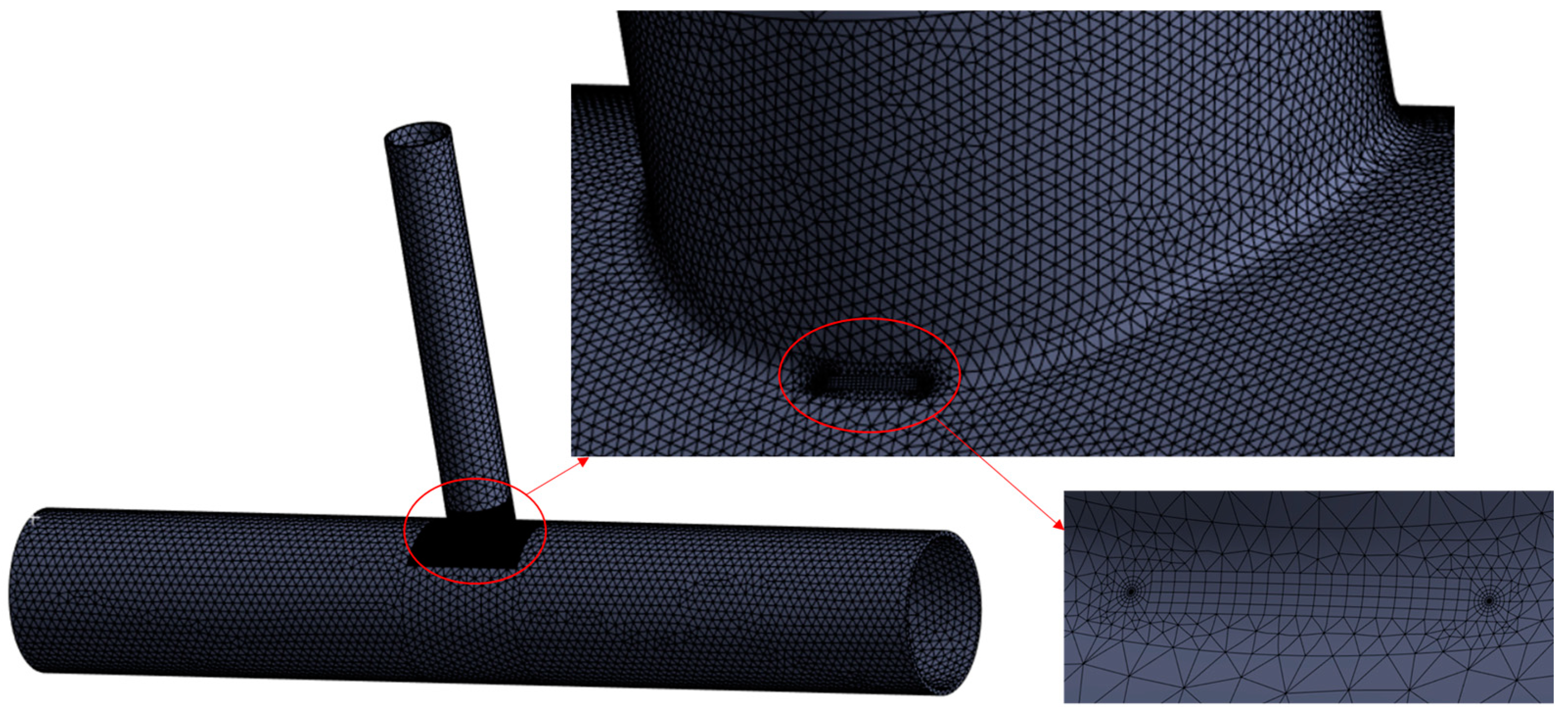
2.2. Finite Element Modeling (FEM)

Among various CAE software, ANSYS Workbench (ANSYS Workbench 2024 R1, ANSYS Inc., Canonsburg, PA, USA, 2024) offers a user-friendly environment with advanced FE modeling and design exploration tools [17]. Various studies on CHS joints have successfully used ANSYS for the analysis of tubular joints [18]. The geometry of the KT-joint was modeled using ANSYS’s DesignModeler. The geometry of the KT-joint was meshed with high-order solid elements using the ANSYS Structural mesh tool, and mesh convergence was ensured. The final mesh has 288,853 elements and 469,095 nodes, as shown in Figure 2.
The geometry and material properties were based on validated parameters from previous studies. The material properties of reinforcement (CFRP) and the joint are listed in Table 1 [19]. The semi-elliptical fatigue crack was introduced along the weld line of the chord–brace intersection using ANSYS’s built-in fracture tool.

2.3. Parametric Study

Four parameters—crack size, crack location, load type, and composite reinforcement—were systematically varied to assess their impact on the SIF. The analysis included three loading conditions: axial tensile, in-plane bending, and out-of-plane bending.

2.4. Mesh Sensitivity Analysis

Mesh convergence studies were conducted for the tubular T-joint and composite reinforcement to ensure computational accuracy and efficiency. Tetrahedral elements were used, with finer meshes applied to the crack and reinforcement regions. The final mesh is illustrated in Figure 2.

2.5. Validation

The FEM results were validated against published experimental and numerical data. Load–displacement correlations were used to verify the accuracy of the model.

2.6. Data Analysis

The SIF values, particularly the maximum mode-I SIF, were extracted and analyzed to evaluate the influence of variables and the effectiveness of composite reinforcement in mitigating fatigue crack propagation.

3. Results and Discussion

This study evaluates the effects of crack position, size, and CFRP reinforcement on the stress intensity factor (SIF) for T-joints subjected to different loading conditions. The results highlight critical insights into the stress distribution and efficacy of CFRP reinforcement in mitigating high SIF values.

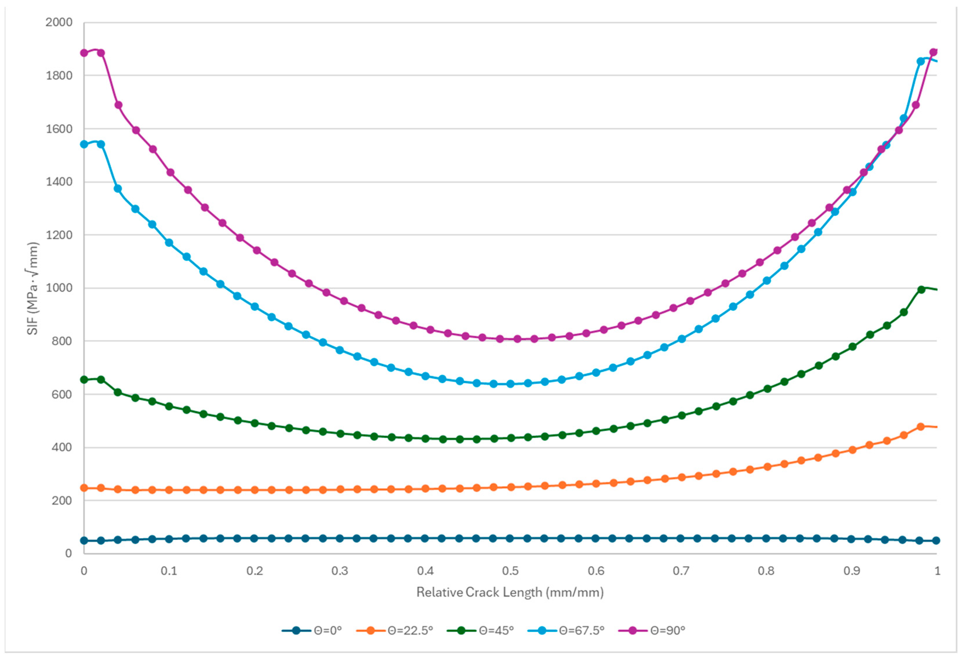
3.1. Effect of Crack Position on SIF

The crack position significantly affects SIF distribution, as shown in Figure 3. For axial tensile loading, SIF values exhibit symmetry at the crown and saddle points due to uniform stress application. The SIF peaks at the crack tip for the saddle point but at the middle section for the crown point, influenced by geometric factors and stress distribution along the crack front. As the crack transitions from the crown to the saddle point, the SIF increases significantly, with the saddle point recording the highest SIF value (1886.9 MPa√mm), approximately 30 times higher than the crown point. This substantial variation underscores the influence of joint geometry and crack orientation on stress redistribution, which aligns with the findings of Iqbal et al. [4].

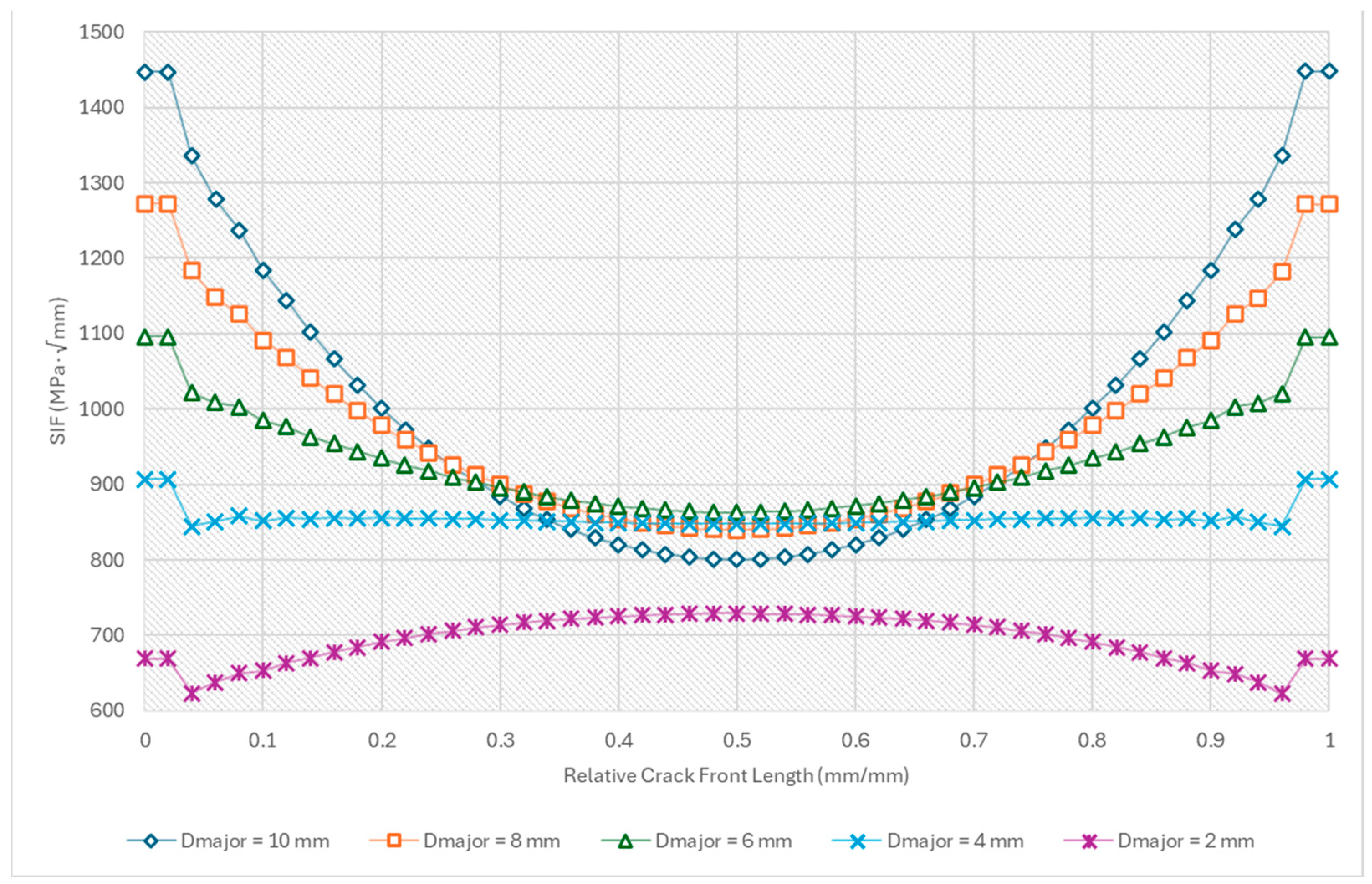
3.2. Effect of Crack Size on SIF

Larger cracks exhibit pronounced stress concentrations at the tips, with SIF curves peaking prominently, as shown in Figure 4. Conversely, smaller cracks demonstrate a more uniform stress distribution, with a reduced SIF at the tips and relatively higher values along the crack middle. This behavior stems from stress redistribution and the plastic zone characteristics around smaller cracks, which reduce stress intensity at the crack tips. For instance, cracks with 2 mm major diameters recorded a peak SIF at their center, unlike larger cracks. These observations corroborate Subbaiah and Bollineni’s [20] findings on cylindrical pressure vessels.

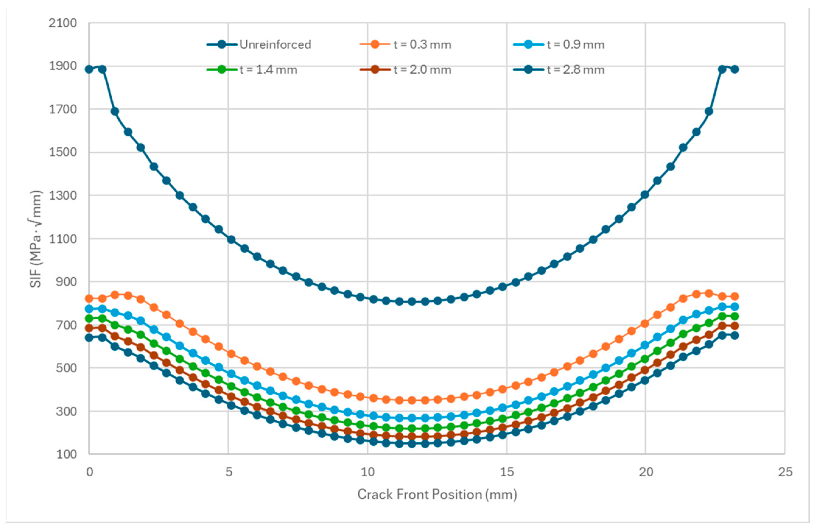
3.3. Effect of CFRP Thickness on SIF

Applying CFRP reinforcement significantly reduces SIF values, with the first CFRP layer lowering the SIF by 53.4%. Further thickness increases yield diminishing returns; for instance, increasing CFRP thickness from 2.0 mm to 2.8 mm results in only a 6% SIF reduction, as shown in Figure 5. This trend highlights the load redistribution capabilities of CFRP and the material’s finite stress absorption capacity. Excessive CFRP thickness should be assessed based on joint severity, cost, and additional weight implications.

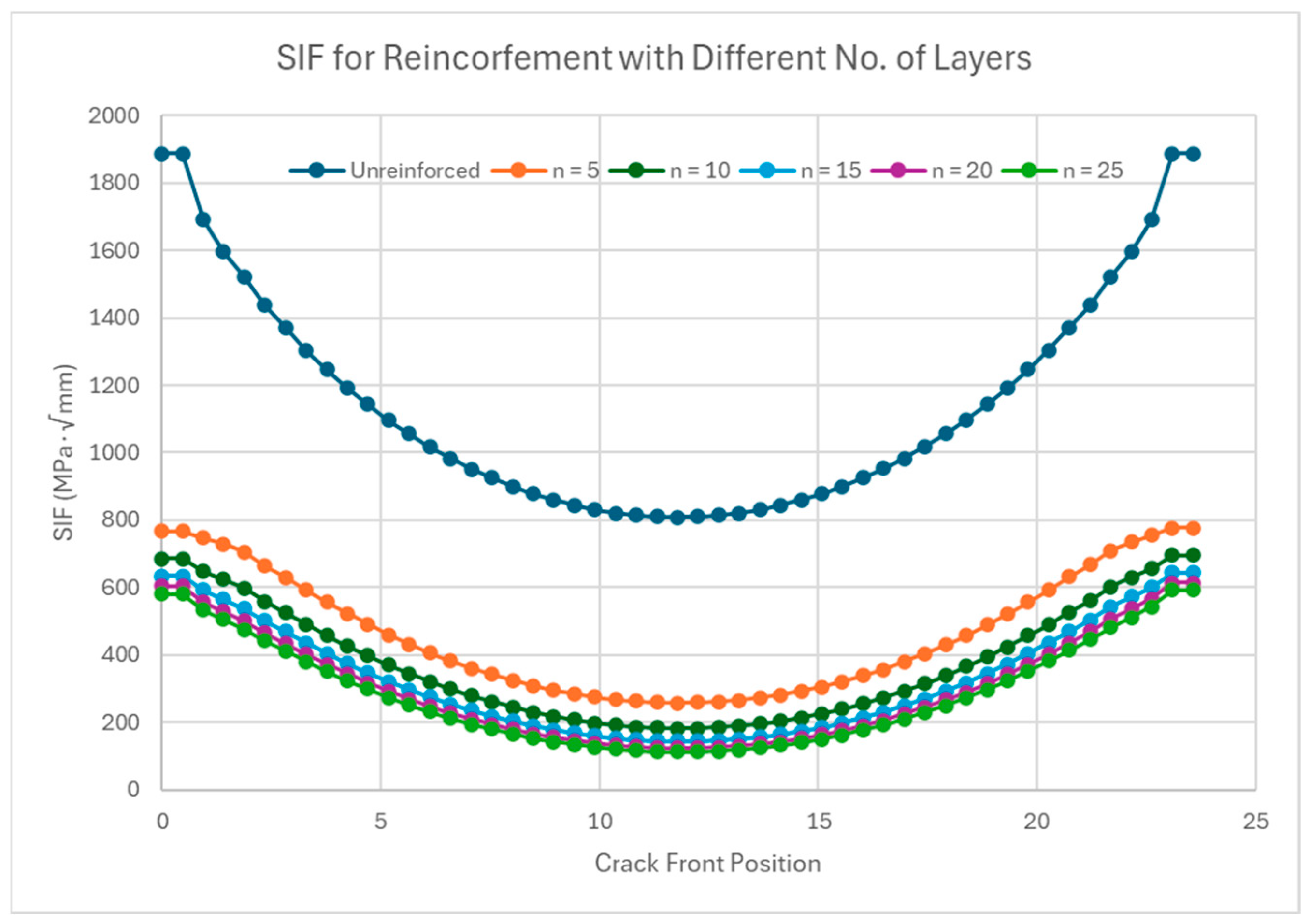
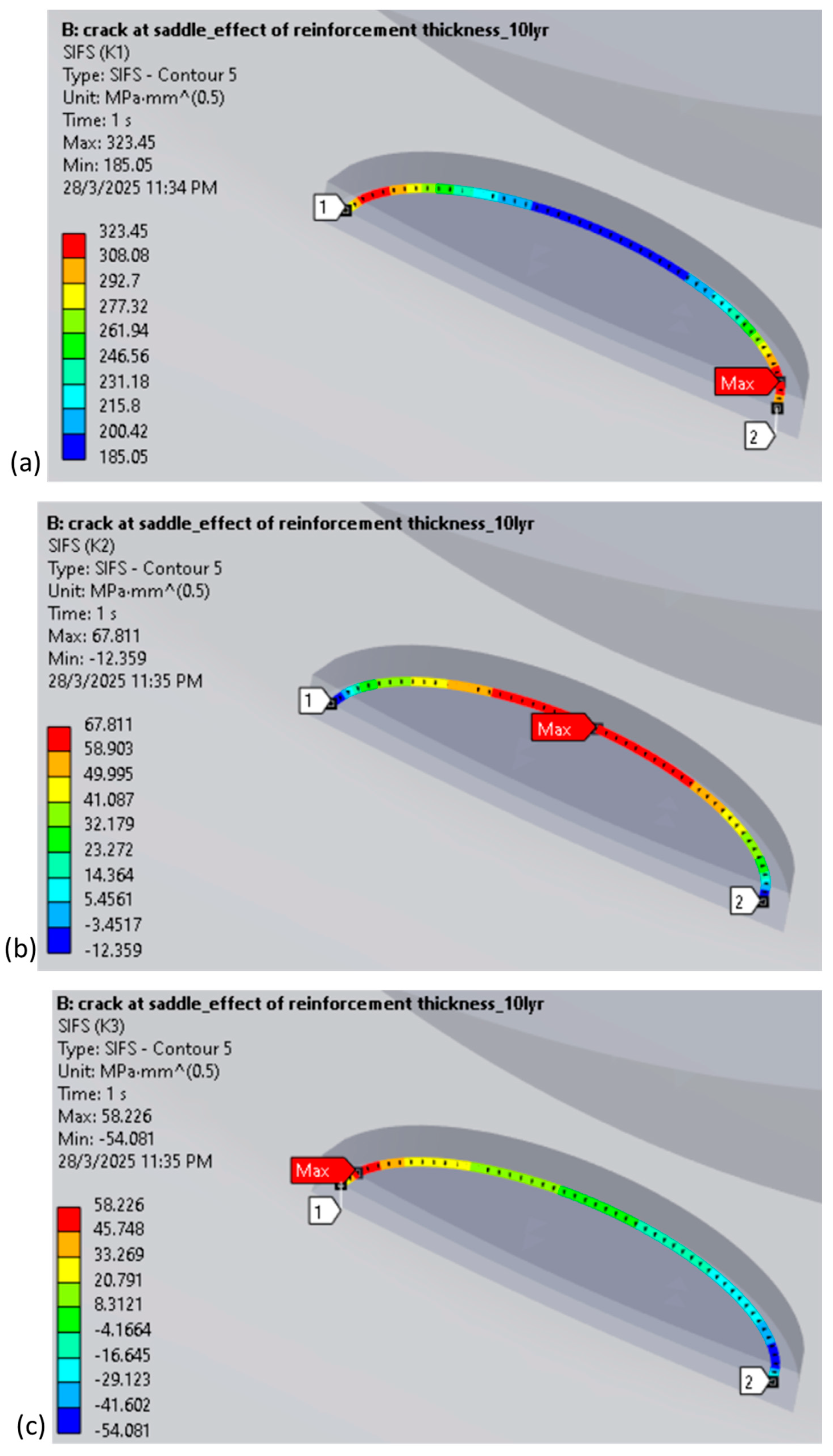
3.4. Effect of CFRP Layers on SIF

Incremental increases in CFRP layers also reduce the SIF, with the initial layers achieving substantial reductions (e.g., 58.5% for five layers), as shown in Figure 6. However, beyond a certain point, additional layers yield marginal reductions, as seen when increasing from 20 to 25 layers (3% reduction). Optimal reinforcement takes into consideration the anisotropic properties of CFRP, with the 0° fiber orientation being most effective for axial tension.
The SIF contours of the SIF for a 30 MPa tensile load applied on the central brace of a typical T-joint reinforced with 10 layers of CFRP, constituting a 2 mm thickness, with a semi-elliptical crack are shown in Figure 7. The higher value of K1 (Figure 7a) indicates that the crack is primarily exhibiting mode-I.

4. Conclusions

This study successfully achieved its objectives by conducting a numerical parametric investigation into the stress intensity factor (SIF) of fatigue-cracked T-joints and evaluating the effectiveness of composite reinforcement as a mitigation strategy. The analysis revealed that the highest SIF values consistently occurred at the saddle point under axial and out-of-plane bending (OPB) loads, while in-plane bending (IPB) loads showed peak SIF values at the 45° position between the crown and saddle points. The results also indicated that the SIF increased proportionally with the size and diameter of the cracks, with larger cracks exhibiting higher SIF values. The application of CFRP wrapping proved effective in reducing the SIF by more than 50% across all loading conditions, with the most significant reductions observed at a 0° orientation. However, further increases in the thickness and layers of CFRP showed diminishing returns, highlighting the importance of proper crack severity assessment to optimize the use of resources and ensure efficient application in real-life scenarios.

Author Contributions

Conceptualization, S.K., and M.I.; analysis, M.H.; writing—original draft preparation, M.H.; writing—review and editing, M.H., and M.I.; supervision, S.K.; project administration, S.K.; funding acquisition, S.K. All authors have read and agreed to the published version of the manuscript.

Funding

This research received funding from Yayasan Universiti Teknologi PETRONAS under grant No. 015LC0-443.

Institutional Review Board Statement

Not applicable.

Informed Consent Statement

Not applicable.

Data Availability Statement

Data are contained within the article.

Conflicts of Interest

The authors declare that there is no conflict of interest regarding the publication of this manuscript.

References

  1. Shi, Y.; Deng, P.; Zhao, S.; Liu, Y.; Zhu, Z.; Chen, Y. Research on the Effect of Geometric Parameters on the Stress Concentration Factor of Multi-Planar KK-Joints and Carbon Fiber-Reinforced Polymer Wrapping Rehabilitation with Numerical Simulation. Buildings 2025, 15, 157. [Google Scholar] [CrossRef]
  2. Rezadoost, P.; Asgarian, B.; Nassiraei, H. Fiber-reinforced polymers effect on the degree of bending in offshore cross-shaped tubular connections under out-of-plane bending. Mar. Struct. 2025, 101, 103776. [Google Scholar] [CrossRef]
  3. Li, Z.; Chang, H.; Ren, T.; Meng, Z.; Yin, Y.; Liu, N.; Huang, Y.; Xia, J. Behavior of reinforced CHS T-joints by welding collar plates under load. Thin-Walled Struct. 2024, 203, 112187. [Google Scholar] [CrossRef]
  4. Iqbal, M.; Karuppanan, S.; Perumal, V.; Ovinis, M.; Rasul, A. Numerical Investigation of Crack Mitigation in Tubular KT-Joints Using Composite Reinforcement. Eng. Proc. 2023, 56, 255. [Google Scholar] [CrossRef]
  5. Nassiraei, H.; Asgarian, B.; Rezadoost, P. Degree of bending in X-connections retrofitted with different types of fiber-reinforced polymers subjected to axial load. Structures 2024, 71, 107964. [Google Scholar] [CrossRef]
  6. Liu, L.; Dong, Y.; Yang, H.; Xu, M.; Liu, X.; Zhang, L.; Garbatov, Y. Hot-Spot Stress Analyses of a T-Shaped Tubular Joint Subjected to Uniform, Grooving and Non-uniform Corrosion. Appl. Sci. 2024, 14, 4812. [Google Scholar] [CrossRef]
  7. Yang, Y.; Min, S.; Peng, Y.; Wang, H.; Chen, C. Experimental and numerical investigation on stress concentration factor of large-scale welded tubular T-joints. Ocean Eng. 2025, 320, 120337. [Google Scholar] [CrossRef]
  8. Rashnooie, R.; Zeinoddini, M.; Ghafoori, E.; Sharafi, M. Experimental and numerical study on the in-plane bending behaviour of FRP-strengthened steel tubular welded T-joints. Thin-Walled Struct. 2024, 201, 112000. [Google Scholar] [CrossRef]
  9. McGeorge, D.; Echtermeyer, A.; Leong, K.; Melve, B.; Robinson, M.; Fischer, K. Repair of floating offshore units using bonded fibre composite materials. Compos. Part A Appl. Sci. Manuf. 2009, 40, 1364–1380. [Google Scholar] [CrossRef]
  10. Zhang, W.; Su, Y.; Jiang, Y.; Hu, Z.; Bi, J.; He, W. Data-driven fatigue crack propagation and life prediction of tubular T-joint: A fracture mechanics based machine learning surrogate model. Eng. Fract. Mech. 2024, 311, 110556. [Google Scholar] [CrossRef]
  11. Wang, Z.-M.; Chang, K.-H.; Hirohata, M. Comparison of Fatigue Life and Crack initiation of T-Shaped CHS and SHS Welding Structures. Int. J. Steel Struct. 2024, 24, 1422–1432. [Google Scholar] [CrossRef]
  12. Ávila, B.V.; Correia, J.; Carvalho, H.; Fantuzzi, N.; De Jesus, A.; Berto, F. Numerical analysis and discussion on the hot-spot stress concept applied to welded tubular KT joints. Eng. Fail. Anal. 2022, 135, 106092. [Google Scholar] [CrossRef]
  13. Iqbal, M.; Karuppanan, S.; Perumal, V.; Ovinis, M.; Iqbal, M.; Rasul, A. Modeling of Stress Concentration Factors in CFRP-Reinforced Circular Hollow Section KT-Joints Under Axial Compression. Eng. Proc. 2025, 87, 19. [Google Scholar] [CrossRef]
  14. Nichols, N.W.; Khan, R. Remediation and Repair of Offshore Structures. In Encyclopedia of Maritime and Offshore Engineering, 1st ed.; Carlton, J., Jukes, P., Sang, C.Y., Eds.; Wiley: Hoboken, NJ, USA, 2018. [Google Scholar] [CrossRef]
  15. Alshoaibi, A.M.; Fageehi, Y.A. A Computational Framework for 2D Crack Growth Based on the Adaptive Finite Element Method. Appl. Sci. 2022, 13, 284. [Google Scholar] [CrossRef]
  16. Iqbal, M.; Karuppanan, S.; Perumal, V.; Ovinis, M.; Khan, A. Stress Concentration Factors in CFRP-Reinforced KT-Joints under Multiplanar Bending Loads: Experimental and Numerical Investigation. Results Eng. 2024, 25, 103745. [Google Scholar] [CrossRef]
  17. Chen, X.; Liu, Y. Finite Element Modeling and Simulation with ANSYS Workbench; CRC Press: Boca Raton, FL, USA, 2015. [Google Scholar] [CrossRef]
  18. Zavvar, E.; Rosa-Santos, P.; Ghafoori, E.; Taveira-Pinto, F. Analysis of tubular joints in marine structures: A comprehensive review. Mar. Struct. 2024, 99, 103702. [Google Scholar] [CrossRef]
  19. Zhang, Y.; Zhang, K.; Zhao, H.; Xin, J.; Duan, M. Stress analysis of adhesive in a cracked steel plate repaired with CFRP. J. Constr. Steel Res. 2018, 145, 210–217. [Google Scholar] [CrossRef]
  20. Subbaiah, A.; Bollineni, R. Stress Intensity Factor of Inclined Internal Edge Crack in Cylindrical Pressure Vessel. J. Fail. Anal. Prev. 2020, 20, 1524–1533. [Google Scholar] [CrossRef]
Figure 1. Stress behavior at a CHS joint [13].
Engproc 87 00038 g001
Figure 2. Meshed model of the KT-joint.
Engproc 87 00038 g002
Figure 3. SIF curves for a crack at different locations.
Engproc 87 00038 g003
Figure 4. SIF for various crack sizes.
Engproc 87 00038 g004
Figure 5. SIF variation with reinforcement thickness.
Engproc 87 00038 g005
Figure 6. SIF for crack reinforced with various numbers of FRP layers.
Engproc 87 00038 g006
Figure 7. Contours of SIF: (a) K1, (b) K2, and (c) K3.
Engproc 87 00038 g007
Table 1. Material properties of base joint and composite reinforcement [19].
ParameterMagnitude
CFRP UDYoung modulus, E x (GPa)134
Young modulus, E y (GPa)10.3
Young modulus, E z (GPa)10.3
Shear modulus, G x y (GPa)5.5
Shear modulus, G y z (GPa)5.5
Shear modulus, G x z (GPa)3.2
Poisson’s ratio, ν x y 0.33
Poisson’s ratio, ν y z 0.53
Poisson’s ratio, ν x z 0.33
Steel pipeYoung modulus, E (GPa)211
Poisson’s ratio, ν 0.3
Disclaimer/Publisher’s Note: The statements, opinions and data contained in all publications are solely those of the individual author(s) and contributor(s) and not of MDPI and/or the editor(s). MDPI and/or the editor(s) disclaim responsibility for any injury to people or property resulting from any ideas, methods, instructions or products referred to in the content.

