1. Introduction
With respect to the navigation function, launch vehicles have traditionally relied solely on high-grade INS (Inertial Navigation Systems) but in the last two decades, there has been an increasing interest in the use of hybrid navigation, fusing GNSS together with INS to achieve GNC (Guidance Navigation and Control) and safeguard function in launcher applications. GNSS is used in applications that require higher accuracy in the long-term than the is achieved by traditional INS-only systems (e.g., reusable stages and re-entry vehicles) and relax the requirements on the INS system, thus lowering system costs (which is especially relevant for micro-launchers). This interest yielded new GNSS/INS navigation systems, some operational like the one on Falcon 9, and some still under development, like the NAVIGA system for the Vega-C launcher. In the case of reusable stages and re-entry vehicles, higher navigation accuracy is required for the last phases associated with the landing. To meet such accuracies, complementary sensors are commonly used; specifically, radar altimeters are typically used for altitude estimation relative to the landing pad.
Despite this, considering the safety-critical applications for launcher and re-entry system environments, such a navigation system must also demonstrate robustness with respect to the possible threats and weaknesses introduced by the GNSS and INS technology. For this reason, the focus of this research is to develop a robust design for a GNSS/INS navigation system while considering recovery mechanisms to reduce the risk (up to acceptable levels) in the case of possible failure or threats which may cause the loss or degradation of the navigation function.
2. Launcher Scenarios
2.1. Use Cases Under Investigation
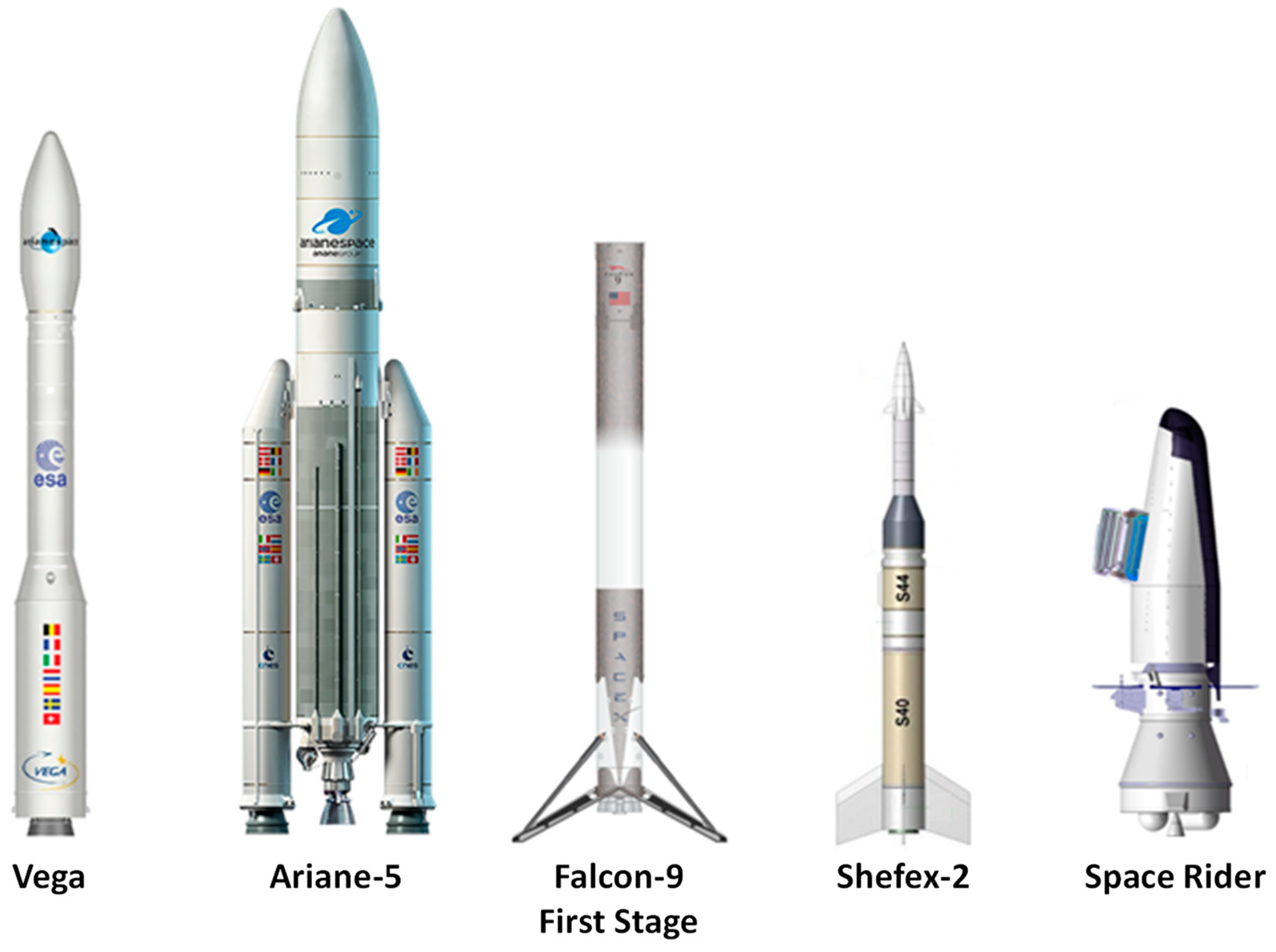
Five use cases (UCs) based on expendable launch vehicles, reusable launch vehicles and re-entry vehicles has been selected in the project (
Figure 1) and the following six mission scenarios (SCs) have been identified to test the robustness of the navigation system architecture:
[SC-001] Vega launch to LEO SSO.
[SC-002] Vega launch to MEO.
[SC-003] Ariane-5 launch to GTO.
[SC-004] Falcon-9 first stage re-entry and landing.
[SC-005] Shefex-2 microgravity mission.
[SC-006] Space Rider re-entry.
2.2. IMU/GNSS Failure and Threats
It is worth noting that a launcher environment is characterized by high levels of accelerations and vibrations. The design parameters, including accounting for shocks and random vibrations, as reported in the launcher user manual [
1], represent the design drivers for payloads and are usually defined with a 99% confidence level. Extreme shock and vibration values that exceed the expected values defined by the launch authority may occur for a short time period during the launch ascent and descent phases, especially during transonic flight and stage separations. Although these events are considered low probability events, they can have a huge impact on the navigation output in terms of attitude and velocity error cumulation. Considering the extensive work reported in [
2] regarding the classifications of failure mode for the navigation sensors, the following threats and failures were selected for this study as part of the DIVERGENCE project: (1) IMU saturation; (2) IMU rectification coning and sculling; (3) INS software failures; (4) ionospheric scintillation; (5) multipath; (6) RF interference; (7) spoofing; (8) satellite/receiver clock bias and drift discontinuity; and (9) IMU/receiver hardware failures.
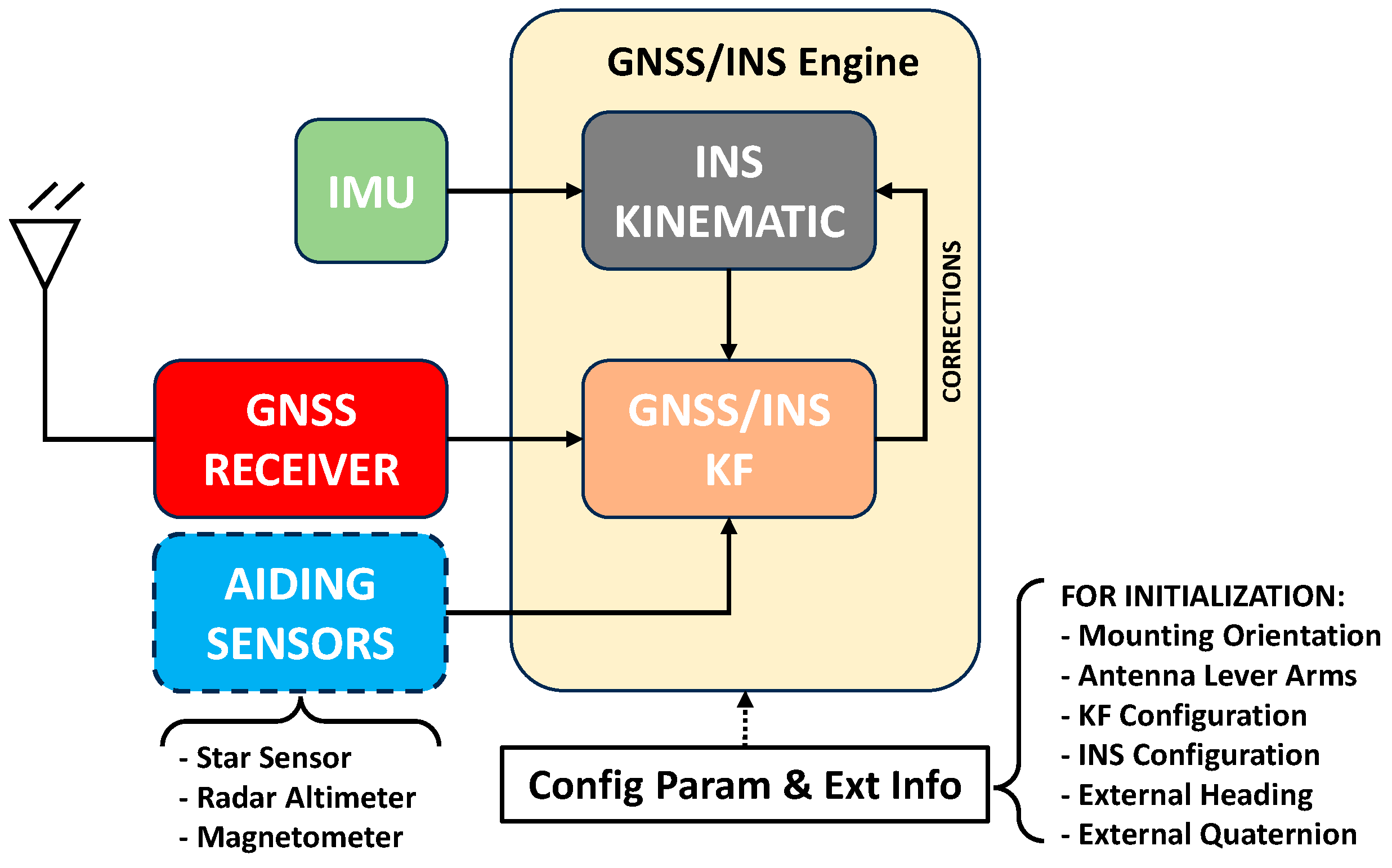
3. Baseline Launcher Navigation Architecture
The baseline launcher navigation system relies on a GNSS/INS sensor fusion engine (
Figure 2). The IMU is considered the primary navigation sensor, which provides high-rate information on angular/velocity increments to the kinematic propagator. The OBS (observables) data message using PR (pseudo-range) or PRR (pseudo-range rate) measurements are primarily used by the GNSS/INS architecture for the TC (tightly coupled) integration. Alternatively, the PVT data message (position, velocity, time) can also be used for the LC (loosely coupled) integration as a backup solution. The use of a multiple-constellation (GPS, Galileo) and multiple-frequency (L1/E1, L5/E5a) GNSS receiver was assumed in accordance with the characteristics of Qascom’s QN400 Space SDR receiver.
Although the system is primarily designed to use the GNSS OBS data message to perform TC integration, other aiding sensors are supported by the sensor fusion engine to extend the capabilities of the navigation system to re-entry space vehicles and other types of local navigation applications (e.g.: drones, aircraft):
Attitude: This information can be provided by a star sensor in quaternion form to initialize/correct the navigation system during the orbital phase before re-entry.
Altitude: This information can be provided by a radar altimeter to enhance the altitude accuracy for re-entry vehicle applications (e.g., Falcon-9) or a barometric altimeter to bound the vertical channel error for drone/aircraft applications.
Heading: This information can be provided by a magnetometer in combination with a WMM (world magnetic model) to reduce the heading error when a low-grade IMU sensor is used in drone/aircraft applications.
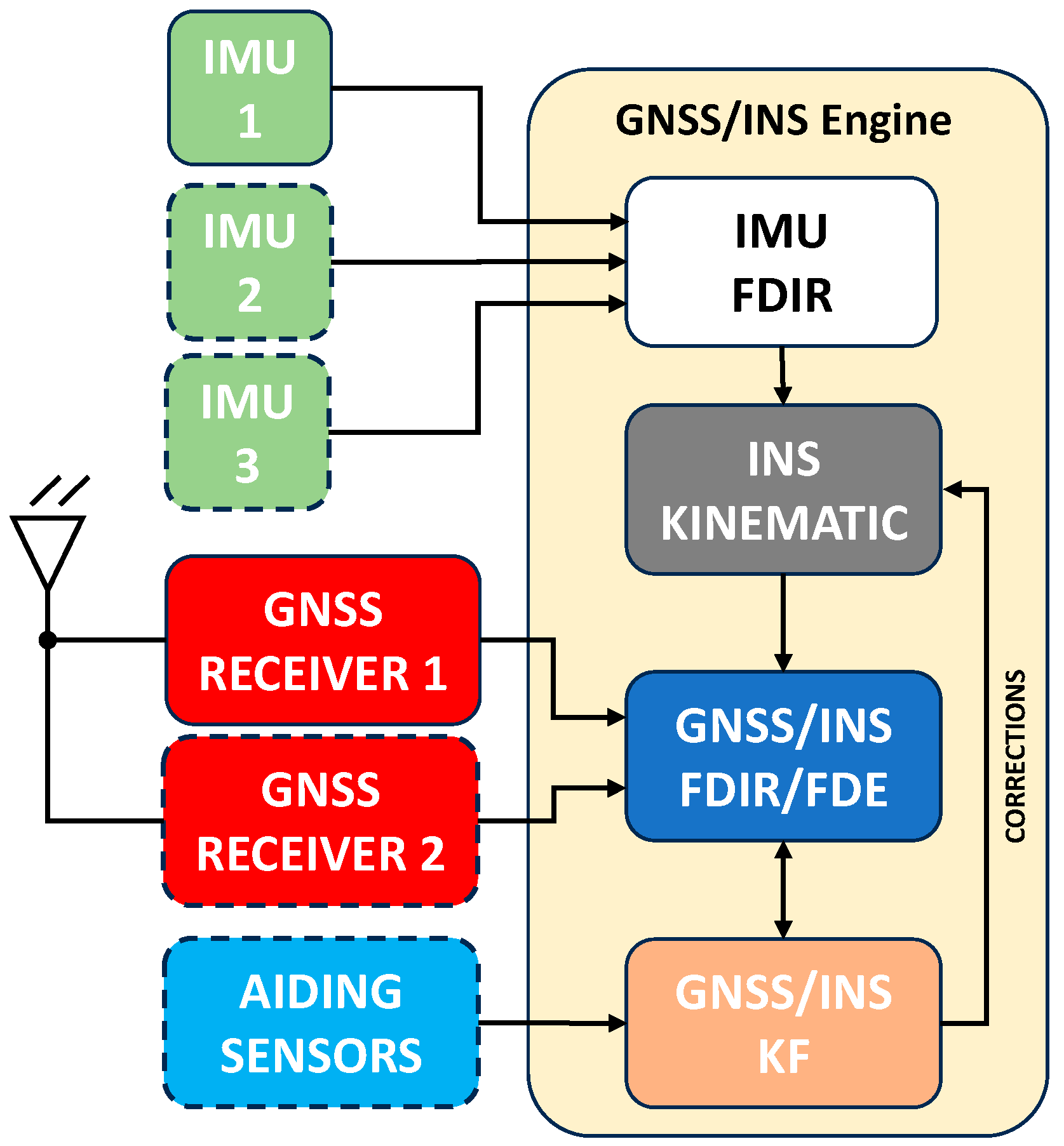
4. Robust Launcher Navigation Architecture
Starting from the baseline launcher navigation architecture, three different techniques have been selected to improve the system robustness. The three techniques work at different levels of the new launcher GNSS/INS engine, as reported in
Figure 3.
IMU FDIR: Assuming a hot redundancy configuration of three IMUs, this technique implements a voting logic to identify the failed IMU and allow the switch to a backup unit in case of failure identification in the primary unit. The algorithm is inspired by the work reported in [
3].
GNSS/INS FDIR: This technique uses a combination of GNSS observables and INS kinematic states to identify out-of-specification drift for the INS and/or receiver clock offset/drift discontinuities. Moreover, the algorithm can identify abrupt changes in single PR/PRR observables caused by satellite failure. The algorithm is inspired by the work reported in [
4].
GNSS/INS FDE: This technique uses a combination of GNSS observables and INS kinematic state to identify slow drift in PR/PRR observables. It is useful to exclude spoofed satellites or observables affected by slow drift change over time. The algorithm is inspired by the work reported in [
5,
6].
4.1. IMU FDIR
The IMU FDIR capability is provided when three IMUs are simultaneously valid in the launcher navigation system. Each IMU is assumed to be a three-axis IMU, and the main scope of the algorithm is to detect and isolate the failed IMU boxes. An alternative approach to IMU FDI could involve the skewing of the IMU boxes to identify failures within individual axes, rather than classifying the entire unit as malfunctioning. However, this method faces challenges due to the typical usage of navigation-grade IMUs in space launch vehicles. These IMUs operate internally at significantly higher rates than the provided output rate. Consequently, the output is subjected to down-sampling and compensation for coning and sculling effects. This compensation process results in a scenario where measurements in each axis are influenced by measurements in the other two axes, inevitably leading to the spread of a failure from one axis to the others. Three IMU boxes are then assumed to be onboard the vehicle, whilst the core of the fault detection and identification is an algorithm which compares a discriminator between the IMU measurement modules with the estimated noise in the discriminator. The estimated noise is mainly a function of the sensor error model and the sensor error specifications. For the theoretical details regarding the FDI algorithm implementation, the reader can refer to the work reported in [
3].
4.2. GNSS/INS FDIR/FDE
The GNSS/INS FDIR/FDE is performed using the combination between the INS kinematic state and the GNSS observables. Its main objective is to provide the filtered observables to the GNSS/INS Kalman filter. The FDIR/FDE architecture is based on a cascade between different FDIR and FDE processing blocks, as reported in
Figure 4. One FDIR and FDE algorithm is utilized for each type of observable provided by the GNSS receiver: PR and PRR. For each type of observable, the FDIR runs first and the FDE is performed second. The sequence between FDIR and FDE is an important design choice and allows the FDIR algorithm to first detect the following: (1) large single GNSS channel blunders; (2) large GNSS channel common mode bias discontinuities; or (3) large INS kinematic state divergences with respect to the GNSS solution. Regarding points 2 and 3, it is important to underline that the FDIR is performed before the FDE algorithm because in the event of a receiver oscillator clock bias/drift discontinuity or a divergence in the INS kinematic, the FDIR algorithm is the first to identify these type of threats, allowing it to adapt the error covariance matrix (from
P to
P′ to
P″) related to the bias/drift or INS kinematic state failure.
The covariance adaptation is the main recovery action performed by the FDIR algorithm, and without this mechanism, a receiver oscillator clock bias/drift discontinuity or a kinematic state divergency at a given time may cause the FDE algorithm to identify all the following observations as invalid, excluding them from their integration in the Kalman filter update phase. FDIR and FDE algorithms are designed to use both PR and PRR measured observations () and predicted observations () to provide a VF (validity flag) vector for each FDIR/FDE processing block as an output. The VF and the full update matrices () are then collected via common exclusion logic to provide the filtered update matrices () to the GNSS/INS Kalman filter and perform the measurement update phase.
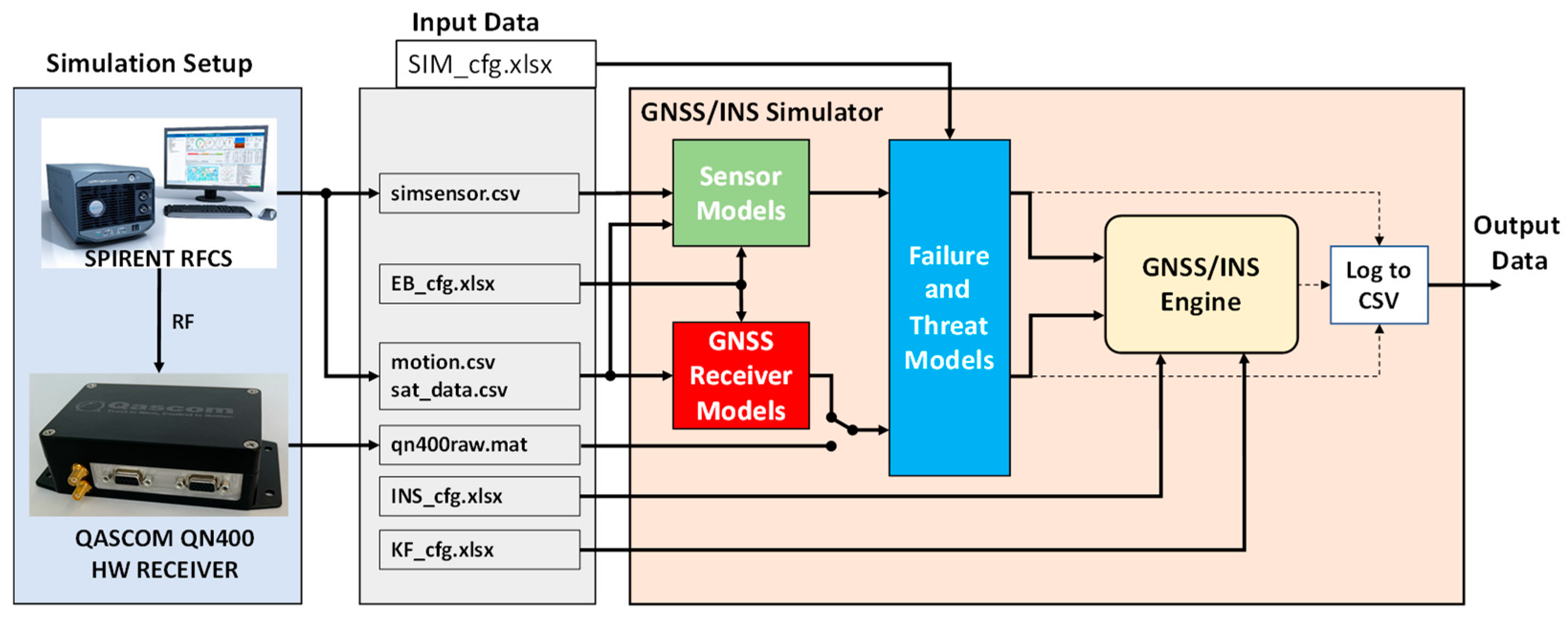
5. Simulation Environment
A simulation environment for the launcher navigation system was designed (
Figure 5) with the main goal to test the GNSS/INS and FDIR/FDE algorithm prototyped in MATLAB (v.23.2) language, allowing the user to perform Monte Carlo simulations and rapidly change the INS/KF configuration based on the space vehicle type (INS_cfg.xlsx) and the sensor error specifications (KF_cfg.xlsx).
Spirent SimGEN/SimSENSOR engines were used to provide the kinematic truth reference, the satellite data (in terms of range and range rates), and the sensors data without errors (IMU, altimeter). A performance error model was implemented for the sensors and the GNSS receiver, enabling the failures and threats to be introduced through a user-defined time-schedule data file (SIM_cfg.xlsx) and an error budget file (EB_cfg.xlsx). The simulator is also capable of using real GNSS receiver data provided by Qascom’s QN400 Space Software Defined Receiver to verify the tracking loop performance of the real receiver in the most representative RF scenario for the future project needs. Moreover, the use of a real GNSS receiver combined with an RF interference generator (such as Qascom QA707) will allow in the future the implementation of scenarios with spoofing and jamming interference performed at the RF level.
6. Simulation Scenario
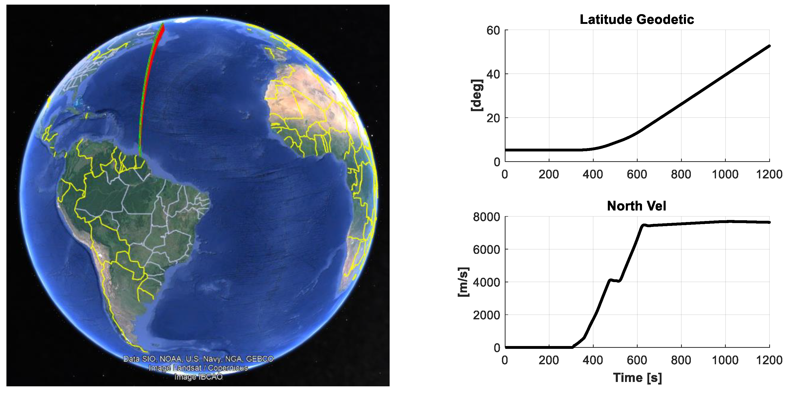
The scenario [SC-001] for the Vega launch into LEO orbit (
Figure 6) was selected to present the results for the robust GNSS/INS architecture. For each threat/failure, a specific ID was defined, and a single simulation was performed to compare the performance of the navigation system with/without the FDIR/FDE algorithm for robust navigation. The threat and failure IDs are defined in
Table 1 and the main flight events, which correspond to the time of failure, are reported in
Table 2. A navigation grade IMU was selected for the Vega scenario applications, and the main error parameters are reported in
Table 3 and are in accordance with the data reported in [
7]. A static period of 5 min was considered at the start of the scenario to allow for the INS system leveling and alignment through ZUPT and to emulate the required period to perform the acquisition and tracking of enough satellites for the GNSS receiver.
7. Simulation Results
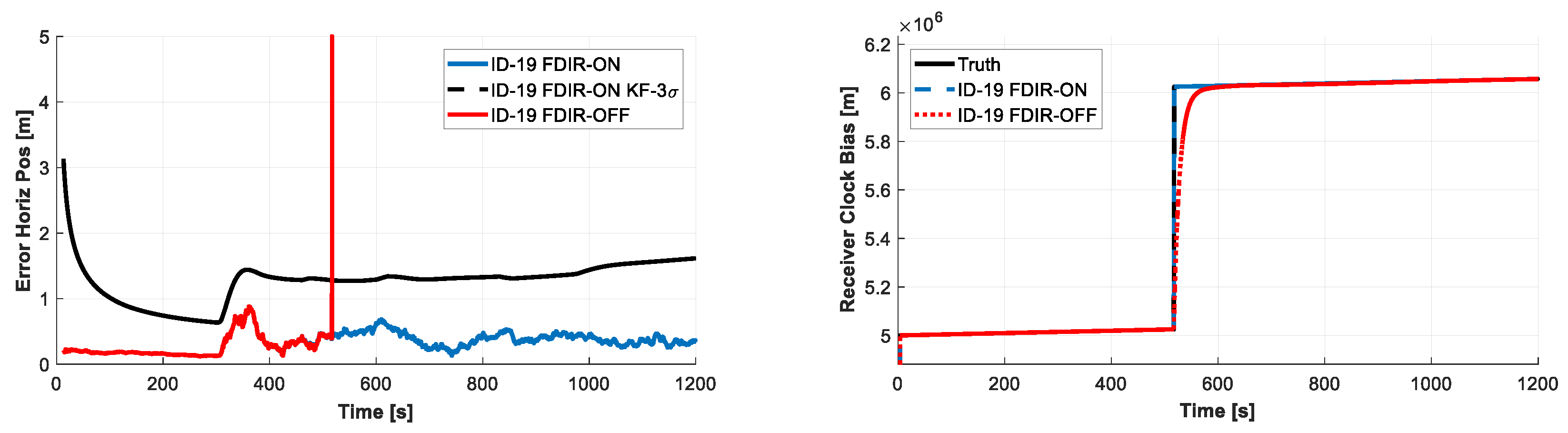
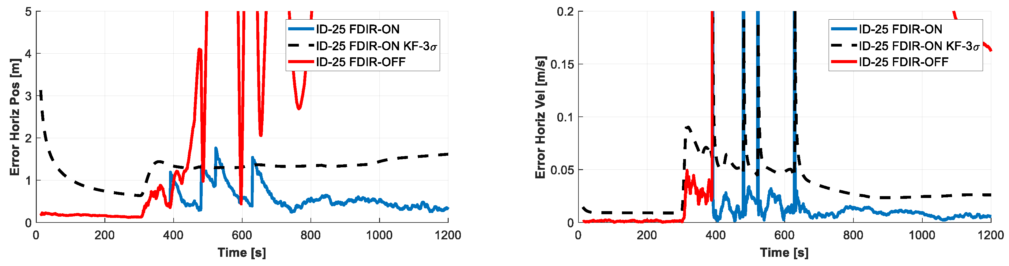
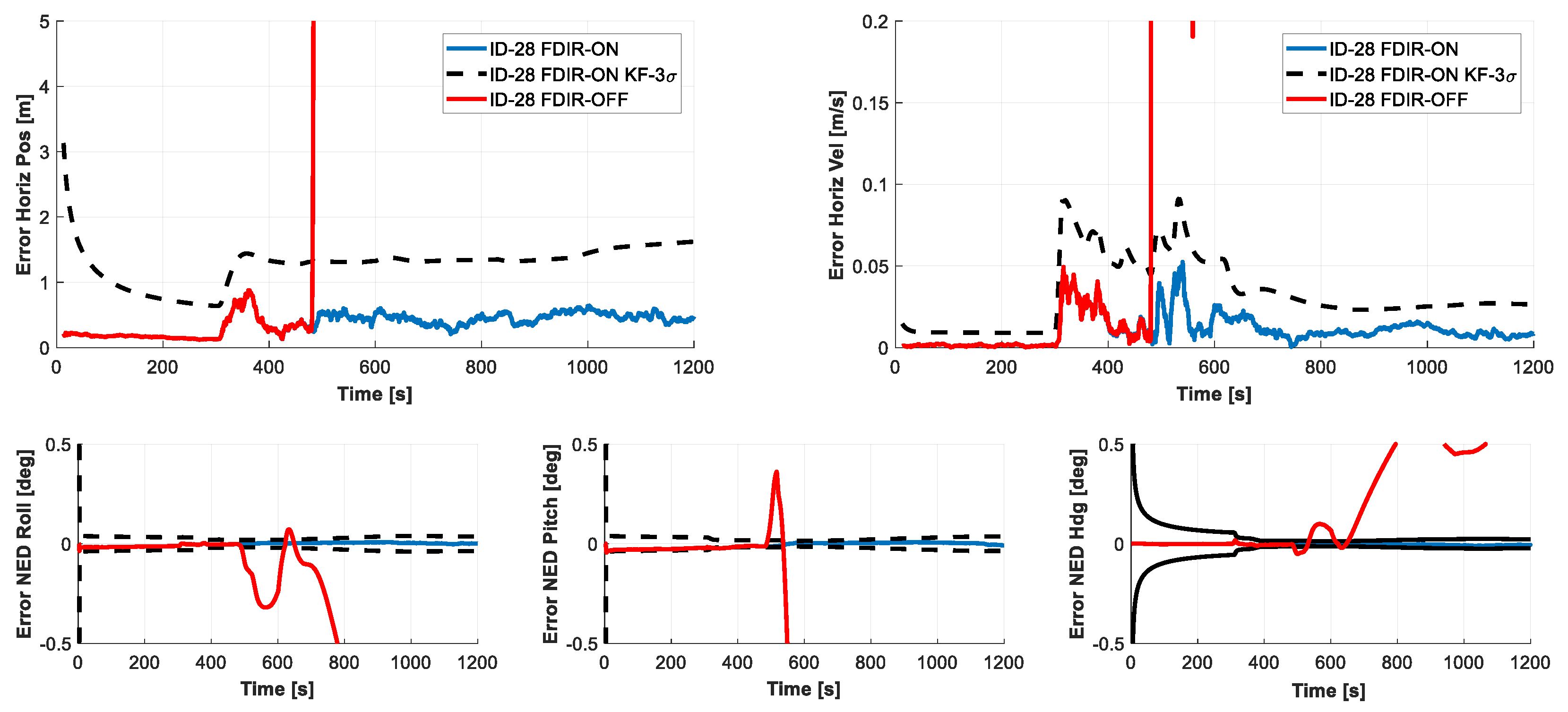
Simulation results are reported for the [SC-001] in terms of normalized RMS error with respect to the accuracy requirements to better identify the most critical threat/failure IDs. The receiver clock discontinuity (ID 19), the IMU accelerometer saturation (ID 25), and the IMU HW failure (ID 28) have the most detrimental effects in terms of performance degradation, as reported in
Figure 7.
The ability of the FDIR algorithm to exclude failures and recover the system in the most serious scenarios is depicted in the following figures with the associated KF-3σ standard deviation. When a receiver clock bias discontinuity is emulated (ID 19), the FDIR algorithm adapts the clock bias KF covariance to respond quickly to the common bias variation in all PR measurements, reducing the position error (see
Figure 8).
When an IMU accelerometer saturation is emulated (ID 25), the FDIR algorithm correctly identifies this failure as an INS kinematic divergency, and thus performs the covariance pumping in the proper KF velocity covariance elements to respond quickly to the discrepancy between the predicted GNSS only and the GNSS/INS solution (see
Figure 9).
When a failure is emulated in the primary IMU (ID 28), the IMU FDIR algorithm correctly identifies the failure and switches the navigation system to use the secondary IMU. The switch to the backup IMU is performed before the failure affects the navigation system kinematic performance, propagating the attitude kinematic states, which can lead to the total failure of the launcher mission (see
Figure 10).
8. Conclusions
In the present work, a new architecture for robust GNSS/INS navigation in launcher applications has been proposed. The new architecture uses a combination of different FDIR/FDE techniques at the GNSS and IMU level to overcome the possible failure and threats introduced in launcher scenarios. A simulation scenario based on MATLAB has been developed to allow for the user to rapidly change the navigator configuration or enable/disable the usage of additional sensors (e.g.: star sensor or radar-altimeter) to select the type of IMU and modify the GNSS receiver model parameters. A comparison between the navigation performance before and after the introduction of the robust navigation techniques has been reported, showing a drastic reduction in the errors, especially regarding receiver clock step failures, accelerometer saturation, and IMU failures, which have been identified as the most detrimental failures for a launcher navigation system.
At the time of writing, the GNSS/INS engine has also been prototyped in C++ and tested on a Zynq 7000-based target platform, considering all the possible sensor data latency that a real-time system must deal with. The future goal for the project is to perform a realistic emulation of the navigation system for launcher applications in terms of simulation environments, sensor performance, and computation capability, leading the way for a possible future integration into an on-board computer.
Author Contributions
Algorithm/software design and implementation, F.S.; launcher trajectory generation: S.C., P.T., and G.P.; writing—review and editing, F.S., S.D.P., B.D.P., and S.F.; supervision, S.F., P.T., G.P., and E.P. All authors have read and agreed to the published version of the manuscript.
Funding
The work reported in this publication was developed in the DIVERGENCE project and was funded by the European Space Agency (ESA) under the contract: “Diversity Architecture for Robust GNSS Receiver in Launcher Application” (ESA contract no. 4000141201/23/NL/CRS).
Institutional Review Board Statement
Not applicable.
Informed Consent Statement
Not applicable.
Data Availability Statement
Data are commercial in confidence.
Conflicts of Interest
Authors Fabio Scibona, Sergi Dueñas Pedrosa, Brendan David Polidori, and Samuele Fantinato were employed by the company Qascom SRL. The remaining authors declare that the research was conducted in the absence of any commercial or financial relationships that could be construed as a potential conflict of interest. The view expressed herein can in no way be taken to reflect the official opinion of the European Space Agency.
References
- Vega Users’s Manual, Issue 4, Revision 0 ed., Arianespace, April 2014. Available online: https://newspaceeconomy.ca/wp-content/uploads/2022/06/vega-users-manual_issue-04_april-2014.pdf (accessed on 1 May 2024).
- Bhatti, U.I.; Ochieng, W.Y. Failure Modes and Models for Integrated GPS/INS Systems. J. Navig. 2007, 60, 327–348. [Google Scholar]
- Zanetti, R.; Alaniz, A.; Breger, L.; Mitchell, I.; Phillips, R. Fault detection and isolation strategy for redundant inertial measurement units. Adv. Astronaut. Sci. 2014, 152, 671–684. [Google Scholar]
- Trigo, G.F. Low-Cost Failure-Tolerant Hybrid Navigation Designs for Future Space Transportation Systems. Ph.D. Thesis, Universität Bremen, Bremen, Germany, 2020. [Google Scholar]
- Diesel, J.; Dunn, G. GPS/IRS AIME: Certification for Sole Means and Solution to RF Interference. In Proceedings of the 9th International Technical Meeting of the Satellite Division of The Institute of Navigation (ION GPS 1996), Kansas City, MO, USA, 17–20 September 1996; pp. 1599–1606. [Google Scholar]
- Sun, R.; Zhang, W.; Zheng, J.; Ochieng, W.Y. GNSSINS Integration with Integrity Monitoring for UAV No-fly Zone Management. Remote Sens. 2020, 12, 524. [Google Scholar]
- Vandersteen, J.; Bennani, S.; Roux, C. Robust Rocket Navigation with Sensor Uncertainties: Vega Launcher Application. J. Spacecr. Rocket. 2018, 55, 153–166. [Google Scholar]
| Disclaimer/Publisher’s Note: The statements, opinions and data contained in all publications are solely those of the individual author(s) and contributor(s) and not of MDPI and/or the editor(s). MDPI and/or the editor(s) disclaim responsibility for any injury to people or property resulting from any ideas, methods, instructions or products referred to in the content. |
© 2025 by the authors. Licensee MDPI, Basel, Switzerland. This article is an open access article distributed under the terms and conditions of the Creative Commons Attribution (CC BY) license (https://creativecommons.org/licenses/by/4.0/).


 ,
, 


