
Sensitivity Analysis of Conformal Cooling Channels for Injection Molds: Two-Dimensional Transient Heat Transfer Analysis †

 ,
,
Abstract
1. Introduction
2. Procedure
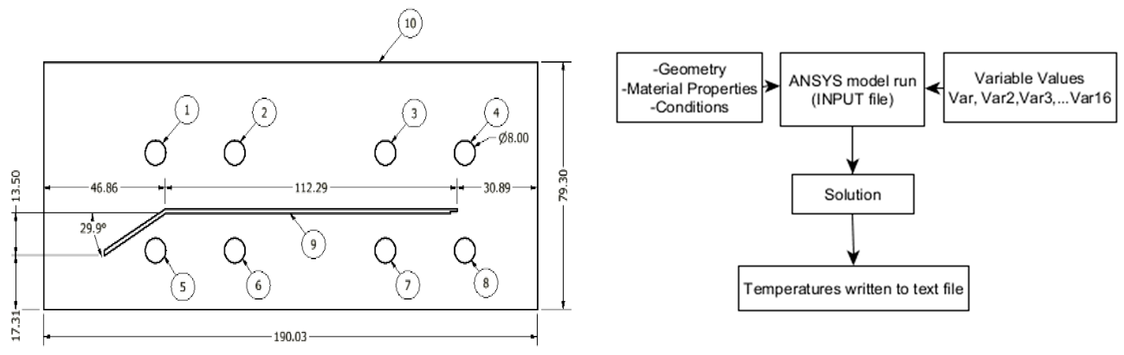
2.1. Geometry and Methodology
2.2. Materials and Conditions
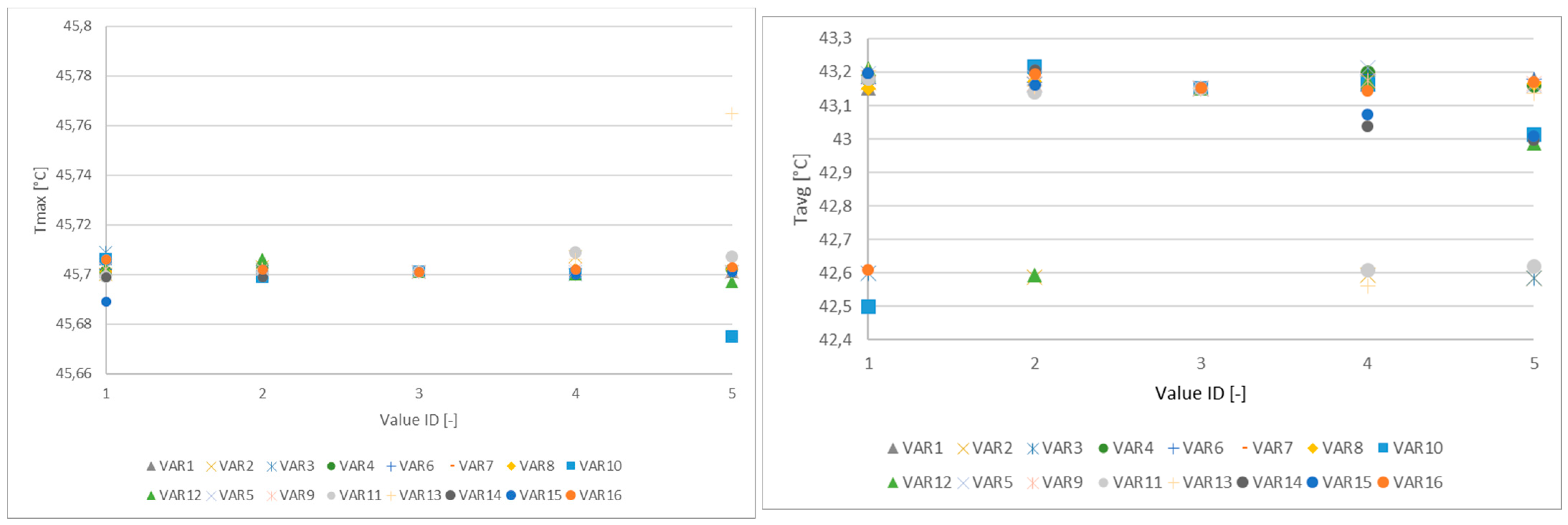
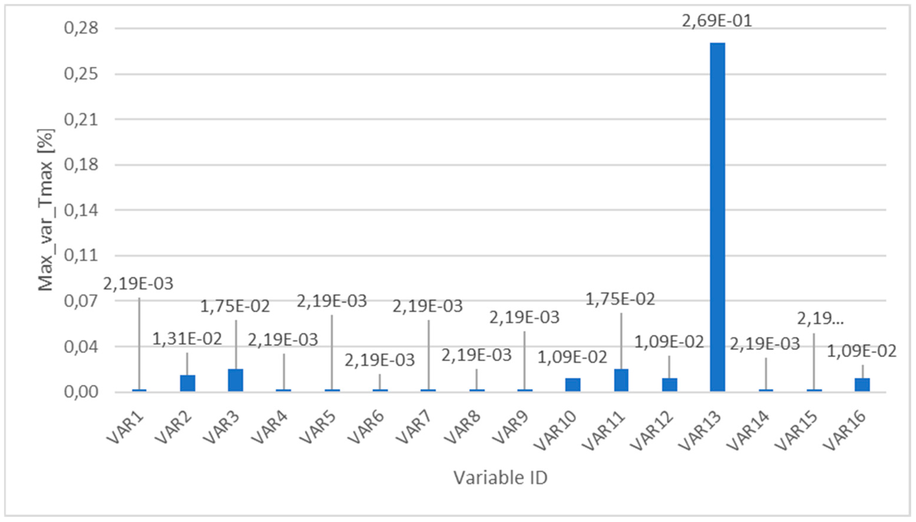
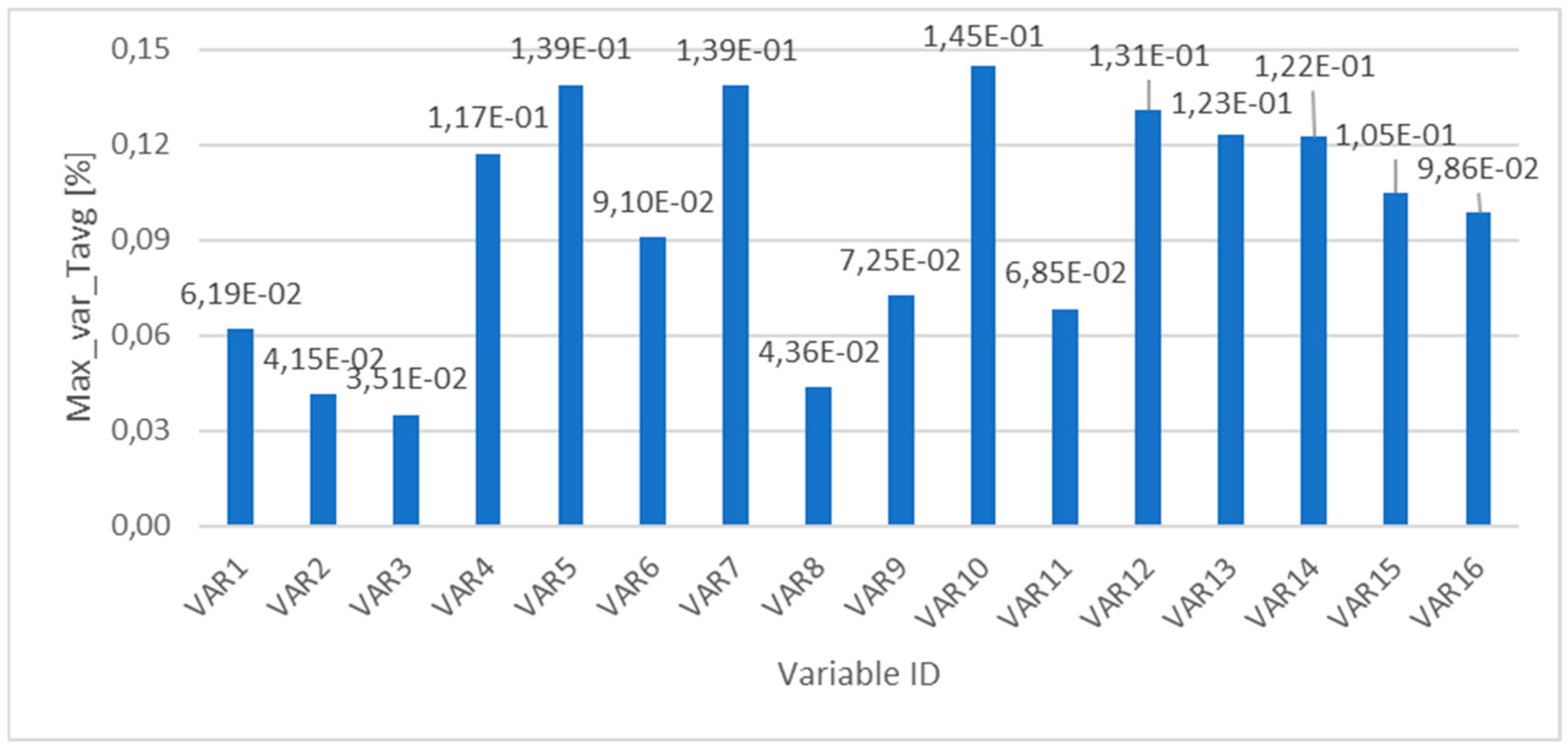
3. Results
4. Conclusions
Author Contributions
Funding
Institutional Review Board Statement
Informed Consent Statement
Data Availability Statement
Conflicts of Interest
References
- Dimla, D.; Camilotto, M.; Miani, F. Design and optimisation of conformal CCs in injection molding tools. J. Mater. Process. Technol. 2005, 164, 1294–1300. [Google Scholar] [CrossRef]
- Saifullah, A.; Masood, S. Finite element thermal analysis of conformal CCs in injection molding. In Proceedings of the 5th Australasian Congress on Applied Mechanics, Brisbane, Australia, 10–12 December 2007. [Google Scholar]
- Saifullah, A.; Masood, S.; Sbarski, I. New CCCS design for injection molding. In Proceedings of the World Congress on Engineering, London, UK, 1–3 July 2009. [Google Scholar]
- Gloinn, T.O.; Hayes, C.; Hanniffy, P.; Vaugh, K. FEA simulation of conformal cooling within injection molds. Int. J. Manuf. Res. 2007, 2, 162–170. [Google Scholar] [CrossRef]
- Au, K.; Yu, K. A scaffolding architecture for conformal cooling design in rapid plastic injection molding. Int. J. Adv. Manuf. Technol. 2007, 34, 496–515. [Google Scholar] [CrossRef]
- Wang, Y.; Yu, K.M.; Wang, C.C.; Zhang, Y. Automatic design of conformal cooling circuits for rapid tooling. Comput.-Aided Des. 2011, 43, 1001–1010. [Google Scholar] [CrossRef]
- Khan, M.; Afaq, S.K.; Khan, N.U.; Ahmad, S. Cycle Time Reduction in Injection Molding Process by Selection of Robust CCCS Design. Int. Sch. Res. Not. 2014, 2014, 968484. [Google Scholar]
- Jauregui-Becker, J.M.; Tragter, H.; van Houten, F.J.A.M. Toward a bottom-up approach to automate the design of cooling systems for injection molding. Comput.-Aided Des. Appl. 2009, 6, 447–459. [Google Scholar] [CrossRef]
- Chung, C.-Y. Integrated optimum layout of conformal cooling channels and optimal injection molding process parameters for optical lenses. Appl. Sci. 2019, 9, 4341. [Google Scholar] [CrossRef]
- Clemente, M.R.; Panão, M.R.O. Introducing flow architecture in the design and optimization of mold inserts cooling systems. Int. J. Therm. Sci. 2018, 127, 288–293. [Google Scholar] [CrossRef]
- Zhang, Y.; Hou, B.; Wang, Q.; Li, Y.; Huang, Z. Automatic design of conformal cooling channels in injection molding tooling. IOP Conf. Ser. Mater. Sci. Eng. 2018, 307, 012025. [Google Scholar] [CrossRef]
- Tuteski, O.; Kocov, A. Conformal cooling channels in injection molding tools–design considerations. Mach. Technol. Mater. 2018, 12, 445–448. [Google Scholar]
- Altaf, K.; Rani, A.M.B.A. Numerical study of profiled conformal cooling channels for cooling time reduction in injection mold tools. Int. J. Eng. Syst. Model. Simul. 2015, 7, 230–237. [Google Scholar] [CrossRef]
- Silva, H.M.; Rodrigues, H.L.; Noversa, J.T.; Fernandes, L.; Pontes, A.J. 2D Heat transfer of an injection mold: ANSYS Workbench and Mechanical APDL. Eng. Proc. 2023, 56, 308. [Google Scholar] [CrossRef]
- Silva, H.M.; Rodrigues, H.L.; Noversa, J.T.; Fernandes, L.; Pontes, A.J. 3D Heat transfer of an injection mold: ANSYS Workbench and Mechanical APD. Eng. Proc. 2023, 56, 298. [Google Scholar] [CrossRef]
- Silva, H.M.; Vasques, C.; Rodrigues, H.L.; Noversa, J.T.; Fernandes, L.; Pontes, A.J. A methodology for the optimal placement of conformal cooling channels in injection molds: 2D transient heat transfer analysis. Int. J. Adv. Manuf. Technol. 2024, 132, 5261–5274. [Google Scholar] [CrossRef]
- Silva, H.M.; Noversa, J.T.; Fernandes, L.; Rodrigues, H.L.; Pontes, A.J. Design optimization of conformal cooling channels for injection molds: 3D transient heat transfer analysis. Mech. Adv. Mater. Struct. 2023, 31, 4610–4621. [Google Scholar] [CrossRef]
- Silva, H.M.; Noversa, J.T.; Fernandes, L.; Rodrigues, H.L.; Pontes, A. Design, simulation and optimization of conformal cooling channels in injection molds: A review. Int. J. Adv. Manuf. Technol. 2022, 120, 4291–4305. [Google Scholar] [CrossRef]
- Silva, H.M.; Noversa, J.T.; Rodrigues, H.L. A review of the design optimization of conformal cooling channels in injection molds. Int. J. Adv. Manuf. Technol. 2025. accepted for publication. [Google Scholar]

| Component ID | Quantity | Description |
|---|---|---|
| 1–-8 | 8 | Channels |
| 9 | 1 | Part |
| 10 | 1 | Mold |
| Component | Designation | Component ID | Direction, as in Figure 1 |
|---|---|---|---|
| CCs | VAR1 | 1 | Horizontal |
| VAR2 | 2 | ||
| VAR3 | 3 | ||
| VAR4 | 4 | ||
| VAR5 | 5 | ||
| VAR6 | 6 | ||
| VAR7 | 7 | ||
| VAR8 | 8 | ||
| VAR9 | 1 | Vertical | |
| VAR10 | 2 | ||
| VAR11 | 3 | ||
| VAR12 | 4 | ||
| VAR13 | 5 | ||
| VAR14 | 6 | ||
| VAR15 | 7 | ||
| VAR16 | 8 | ||
| Part | - | 9 | - |
| Mold | - | 10 | - |
| Material | Water in Liquid State | PP, with 10% Mineral | P20 Steel |
|---|---|---|---|
| Application | Cooling channels (inside) | Injected part | Mold |
| Density [(kg/m3)] | 998.2 | 1050 | 7861 |
| Specific heat [J/(kg · °C] | 4182 | 1800, considered constant | 502.48 |
| Thermal conductivity [W/(m · K)] | 0.6 | 0.2, considered constant | 41.5 |
| Condition | Component ID (Figure 1) | Value °C | Application |
|---|---|---|---|
| Initial Temperature, varies with time | 9 | 210 | Part, 1 area |
| 1–8 | 40 | Cooling channels, 8 areas | |
| Temperature, constant | 10 | 40 | Mold, 1 area |
| 10 | 23 | Boundary, 4 lines |
| Var ID | 1 | 2 | 3 | 4 | 5 |
|---|---|---|---|---|---|
| Var1 | 5 | 7.5 | 10 | 12.5 | 15 |
| Var2 | 5 | 7.5 | 10 | 12.5 | 15 |
| Var3 | 5 | 7.5 | 10 | 12.5 | 15 |
| Var4 | 5 | 7.5 | 10 | 12.5 | 15 |
| Var5 | 2.5 | 3.75 | 5 | 6.25 | 7.5 |
| Var6 | 5 | 7.5 | 10 | 12.5 | 15 |
| Var7 | 5 | 7.5 | 10 | 12.5 | 15 |
| Var8 | 5 | 7.5 | 10 | 12.5 | 15 |
| Var9 | 7.5 | 10 | 12.5 | 15 | 17.5 |
| Var10 | 5 | 7.5 | 10 | 12.5 | 15 |
| Var11 | 7.5 | 8.75 | 10 | 11.25 | 12.5 |
| Var12 | 5 | 7.5 | 10 | 12.5 | 15 |
| Var13 | 1 | 2 | 3 | 4 | 5 |
| Var14 | 2 | 4 | 6 | 8 | 10 |
| Var15 | 2 | 4 | 6 | 8 | 10 |
| Var16 | 2 | 4 | 6 | 8 | 10 |
Disclaimer/Publisher’s Note: The statements, opinions and data contained in all publications are solely those of the individual author(s) and contributor(s) and not of MDPI and/or the editor(s). MDPI and/or the editor(s) disclaim responsibility for any injury to people or property resulting from any ideas, methods, instructions or products referred to in the content. |
© 2025 by the authors. Licensee MDPI, Basel, Switzerland. This article is an open access article distributed under the terms and conditions of the Creative Commons Attribution (CC BY) license (https://creativecommons.org/licenses/by/4.0/).
Share and Cite
Silva, H.M.; Noversa, J.T.; Fernandes, L.; Rodrigues, H.L.; Pontes, A.J. Sensitivity Analysis of Conformal Cooling Channels for Injection Molds: Two-Dimensional Transient Heat Transfer Analysis. Eng. Proc. 2025, 87, 16. https://doi.org/10.3390/engproc2025087016
Silva HM, Noversa JT, Fernandes L, Rodrigues HL, Pontes AJ. Sensitivity Analysis of Conformal Cooling Channels for Injection Molds: Two-Dimensional Transient Heat Transfer Analysis. Engineering Proceedings. 2025; 87(1):16. https://doi.org/10.3390/engproc2025087016
Chicago/Turabian StyleSilva, Hugo Miguel, João Tiago Noversa, Leandro Fernandes, Hugo Luís Rodrigues, and António José Pontes. 2025. "Sensitivity Analysis of Conformal Cooling Channels for Injection Molds: Two-Dimensional Transient Heat Transfer Analysis" Engineering Proceedings 87, no. 1: 16. https://doi.org/10.3390/engproc2025087016
APA StyleSilva, H. M., Noversa, J. T., Fernandes, L., Rodrigues, H. L., & Pontes, A. J. (2025). Sensitivity Analysis of Conformal Cooling Channels for Injection Molds: Two-Dimensional Transient Heat Transfer Analysis. Engineering Proceedings, 87(1), 16. https://doi.org/10.3390/engproc2025087016