
The Utilization of Printed Circuit Boards (PCBs) in Axial Flux Machines: A Systematic Review †


Abstract
1. Introduction
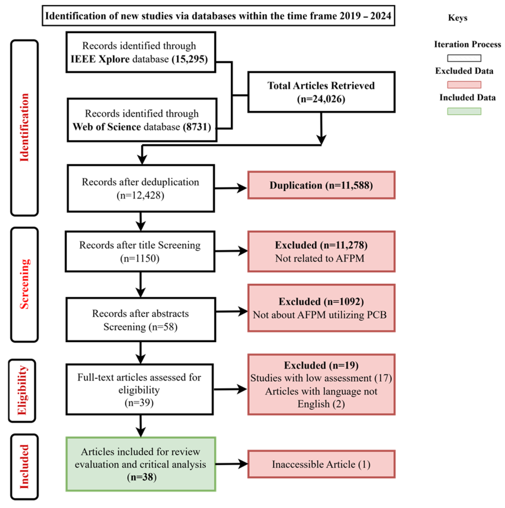
2. Methodology
2.1. Review Method
2.2. Research Questions
- What are the recent advancements in PCB manufacturing or design technology?
- How does the integration of PCBs into AFPM machines affect its performance?
- What are the classifications of PCB-based winding designs?
- How do they minimize the effects of thermal losses experienced?
2.3. Review Strategy
2.4. Inclusion and Exclusion Criteria
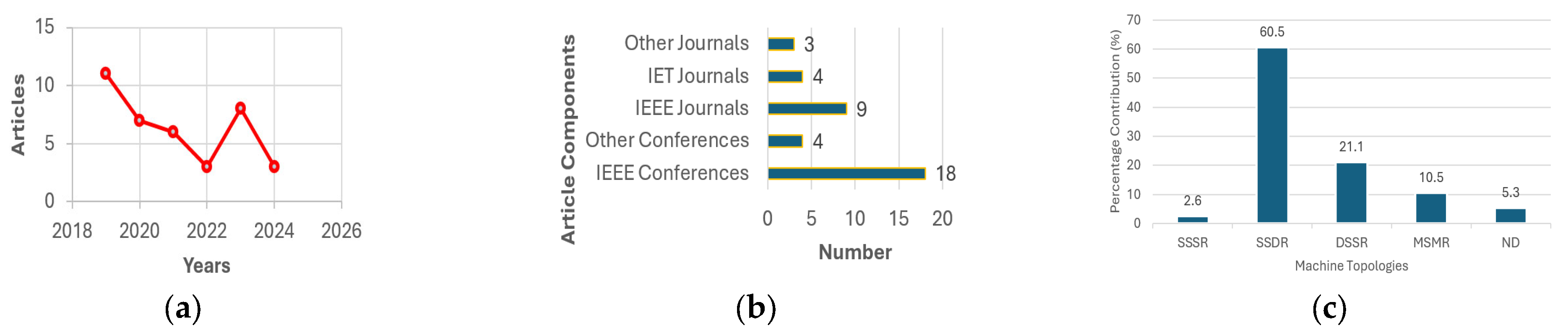
2.5. Data Extraction and Analysis
3. Results for Data Synthesis
3.1. Advancements in PCB Manufacturing
3.2. Defect Mitigation Strategies
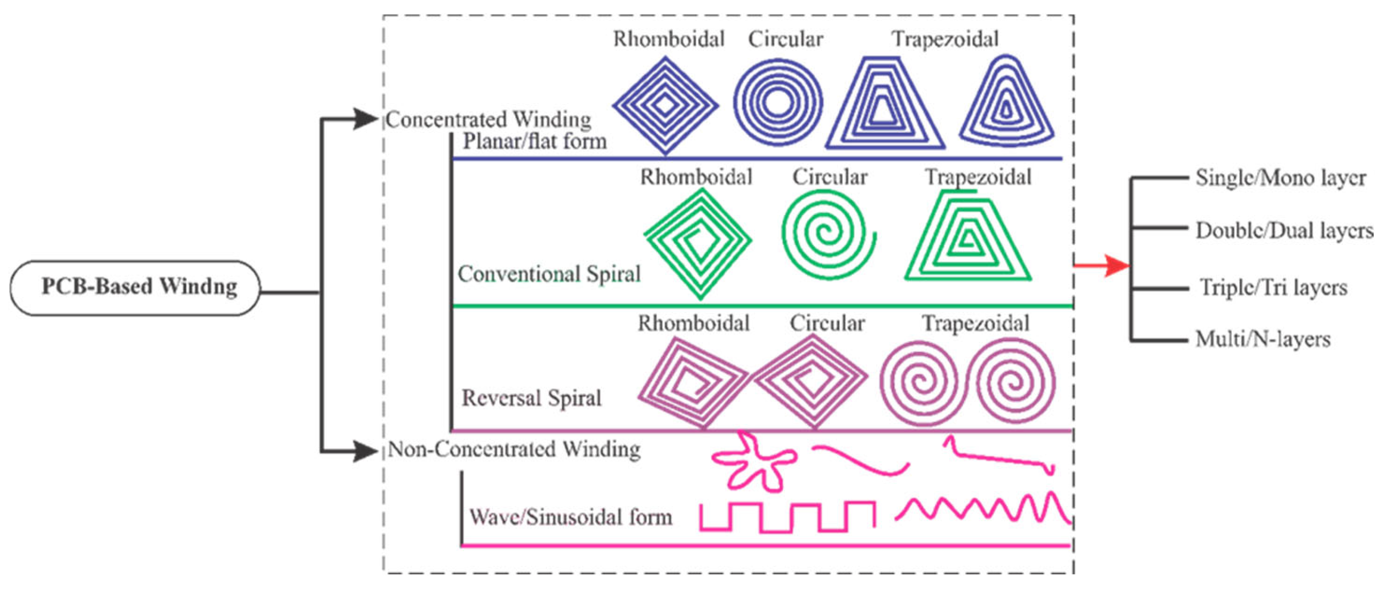
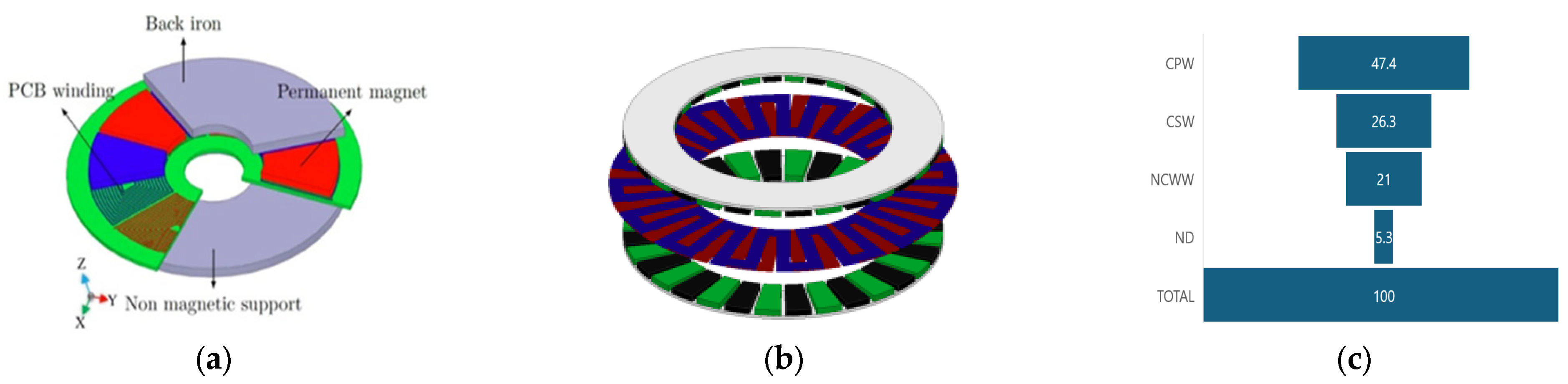
3.3. PCB-Based Winding Configurations
3.3.1. Concentrated Planar Windings (CPWs)
3.3.2. Concentrated Spiral Windings (CSPs)
3.3.3. Non-Concentrated Wave Windings (NCWWs)
3.4. Optimization of Design Utilizing Software Tools
3.5. PCB Winding Wiring Strategy
3.6. PCB-Based Winding and Their Practical Applications
3.7. Thermal Control and Related Losses from PCB Winding Arrangements for AFPMM
3.7.1. Thermal Management Challenges in PCB Winding Configurations
- Optimized Winding Design: the careful design of the trace geometry, such as increasing trace width and optimizing the copper fill factor, can reduce resistance and minimize I²R losses.
- Advanced Materials: high-conductivity copper and thermally enhanced PCB substrates, such as ceramic-filled composites, are used to improve heat dissipation.
- Efficient Cooling Mechanisms: Incorporating direct liquid cooling channels into the PCB structure allows for active heat removal. For instance, adding thermal vias within the PCB can enhance vertical heat transfer to external cooling systems.
- Thermal Simulations: these simulations guide the placement of thermal vias and the optimization of trace layouts for uniform heat distribution.
3.7.2. Loss Mitigation
4. Recommendations
- Nanomaterials: the development of nano-scale materials will enable PCBs with even better performance characteristics, including faster signal transmission, higher thermal conductivity, and improved mechanical strength;
- Artificial Intelligence and Machine Learning: these algorithms can be applied to optimize PCB design and detect defects, enhancing the reliability and lifespan of PCBs;
- Smart PCBs: future PCBs may feature integrated sensors, microprocessors, and wireless communication capabilities, making them more intelligent.
5. Conclusions
Author Contributions
Funding
Institutional Review Board Statement
Informed Consent Statement
Data Availability Statement
Acknowledgments
Conflicts of Interest
References
- Shuaibu, I.; Wei, E.H.T.; Kannan, R.; Aderinola, M.; Adedayo, H.B.; Samaila, Y.A.; Salisu, H.M.; Adebanjo, A.U. State-of-Art Review of Renewable Energy-Based Systems for Electrical Machine Applications: Prospects and Challenges. IOP Conf. Ser. Earth Environ. Sci. 2024, 1365, 012005. [Google Scholar] [CrossRef]
- Wang, S.; Lin, M. Optimal Slot/Pole Combination of Axial-Field Flux-Modulated Machines With Split Teeth. IEEE Trans. Appl. Supercond. 2024, 34, 5208106. [Google Scholar] [CrossRef]
- Habib, A.; Zainuri, M.A.A.M.; Che, H.S.; Ibrahim, A.A.; Rahim, N.A.; Alaas, Z.M.; Ahmed, M.M.R. A systematic review on current research and developments on coreless axial-flux permanent-magnet machines. IET Electr. Power Appl. 2022, 16, 1095–1116. [Google Scholar] [CrossRef]
- Shuaibu, I.; Wei, E.H.T.; Kannan, R.; Samaila, Y.A. Advancements in axial flux permanent magnet machines utilizing coreless technology: A systematic review. Ain Shams Eng. J. 2024, 15, 103091. [Google Scholar] [CrossRef]
- Marignetti, F.; Volpe, G.; Mirimani, S.M.; Cecati, C. Electromagnetic Design and Modeling of a Two-Phase Axial-Flux Printed Circuit Board Motor. IEEE Trans. Ind. Electron. 2018, 65, 67–76. [Google Scholar] [CrossRef]
- Schafer, J.; Bortis, D.; Kolar, J.W. Novel Highly Efficient/Compact Automotive PCB Winding Inductors Based on the Compensating Air-Gap Fringing Field Concept. IEEE Trans. Power Electron. 2020, 35, 9617–9631. [Google Scholar] [CrossRef]
- Neethu, S.; Nikam, S.P.; Singh, S.; Pal, S.; Wankhede, A.K.; Fernandes, B.G. High-Speed Coreless Axial-Flux Permanent-Magnet Motor With Printed Circuit Board Winding. IEEE Trans. Ind. Appl. 2019, 55, 1954–1962. [Google Scholar] [CrossRef]
- Tokgöz, F.; Çakal, G.; Keysan, O. Comparison of PCB winding topologies for axial-flux permanent magnet synchronous machines. IET Electr. Power Appl. 2020, 14, 2577–2586. [Google Scholar] [CrossRef]
- de Jong, E.; Ferreira, J.; Bauer, P. 3D Integration with PCB Technology. In Proceedings of the Twenty-First Annual IEEE Applied Power Electronics Conference and Exposition, APEC ’06, Dallas, TX, USA, 19–23 March 2006; IEEE: Piscataway, NJ, USA, 2006; pp. 857–863. [Google Scholar] [CrossRef]
- Ratna, S.; Vishwakarma, P.N.; Ojha, M.; Kannojiya, R.; Shubham, P.; Sharma, S. Evaluation of PCB materials for high frequency power applications using MOORA method. J. Phys. Conf. Ser. 2022, 2178, 012021. [Google Scholar] [CrossRef]
- Paul, S.; Farshadnia, M.; Pouramin, A.; Fletcher, J.; Chang, J. Printed Circuit Axial-Flux Permanent Magnet Machines: A Comparative Analysis of Their PCB Topologies and Performance Characteristics. In Proceedings of the 2018 IEEE International Magnetics Conference (INTERMAG), Singapore, 23–27 April 2018; p. 1. [Google Scholar] [CrossRef]
- Wang, X.; Yin, C.; Li, T. Thermal Modeling and Analysis of Axial Flux Permanent Magnet Machine with PCB Stator. In Proceedings of the 2022 International Conference on Electrical Machines and Systems, ICEMS, Chiang Mai, Thailand, 29 November–2 December 2022; pp. 1–5. [Google Scholar] [CrossRef]
- Chen, X.; Wu, Y.; He, X.; Ming, W. A Comprehensive Review of Deep Learning-Based PCB Defect Detection. IEEE Access 2023, 11, 139017–139038. [Google Scholar] [CrossRef]
- Pickering, C.; Byrne, J. The benefits of publishing systematic quantitative literature reviews for PhD candidates and other early-career researchers. High. Educ. Res. Dev. 2014, 33, 534–548. [Google Scholar] [CrossRef]
- Kitchenham, B. Guidelines for performing Systematic Literature Reviews in software engineering. EBSE Technical Report EBSE-2007-01 Guidelines for performing Systematic Literature Reviews in Software Engineering. ICSE 2007, 2021, 1–57. [Google Scholar]
- Marcolini, F.; De Donato, G.; Capponi, F.G.; Caricchi, F. Design of a Printed Circuit Board Axial Flux Permanent Magnet Machine for High Speed Applications. IEEE Trans. Ind. Appl. 2024, 60, 5919–5930. [Google Scholar] [CrossRef]
- Baudart, F.; Dehez, B.; Denies, J.; Markovic, M.; Perriard, Y. Shape optimization of flexible PCB slotless windings in BLDC machines. In Proceedings of the 2013 International Conference on Electrical Machines and Systems (ICEMS), Busan, Republic of Korea, 26–29 October 2013; IEEE: Piscataway, NJ, USA, 2013; pp. 943–948. [Google Scholar] [CrossRef]
- Kanygina, E.D.; Denisova, O.V.; Rastvorova, I.V. Optical and Electrical Control in Printed Circuit Board Manufacturing. In Proceedings of the 2019 IEEE Conference of Russian Young Researchers in Electrical and Electronic Engineering (EIConRus), Saint Petersburg and Moscow, Russia, 28–31 January 2019; pp. 536–538. [Google Scholar] [CrossRef]
- Yee, C.F.; Jambek, A.B.; Al-Hadi, A.A. Advantages and Challenges of 10-Gbps Transmission on High-Density Interconnect Boards. J. Electron. Mater. 2016, 45, 3134–3141. [Google Scholar] [CrossRef]
- Wang, W.; Wang, W.; Mi, H.; Mao, L.; Zhang, G.; Liu, H.; Wen, Y. Study and Optimal Design of a Direct-Driven Stator Coreless Axial Flux Permanent Magnet Synchronous Generator with Improved Dynamic Performance. Energies 2018, 11, 3162. [Google Scholar] [CrossRef]
- Guo, H.; Lv, R.; Bai, S. Recent advances on 3D printing graphene-based composites. Nano Mater. Sci. 2019, 1, 101–115. [Google Scholar] [CrossRef]
- Szabó, L.; Fodor, D. The Key Role of 3D Printing Technologies in the Further Development of Electrical Machines. Machines 2022, 10, 330. [Google Scholar] [CrossRef]
- Shuaibu, I.; Ho, E.T.W. Investigation of a Spiral Planar Coil on Coreless Axial Flux PM Generator for Pico-Hydro Applications. In Proceedings of the 2023 IEEE Conference on Energy Conversion (CENCON), Kuching, Malaysia, 23–24 October 2023; IEEE: Piscataway, NJ, USA, 2023; pp. 58–63. [Google Scholar] [CrossRef]
- Guo, H.; Zhao, H.; Zhao, Y.; Liu, W. PCB defect detection algorithm based on deep learning. Optik 2024, 315, 172036. [Google Scholar] [CrossRef]
- Wang, L.T.N.; Simcoe, M.; Mehrotra, V.; Huda, R.; Lee, Z.C.; McKay, T.; Schroeder, P.; Madhavan, S. Electrical design-for-manufacturability (DFM) checks for reducing layout-induced circuit variability for analog designs. In Design-Process-Technology Co-Optimization XV; Yuan, C.-M., Kim, R.-H., Eds.; SPIE: Pune, Indian, 2021; p. 19. [Google Scholar] [CrossRef]
- Dai, W.; Mujeeb, A.; Erdt, M.; Sourin, A. Soldering defect detection in automatic optical inspection. Adv. Eng. Inform. 2020, 43, 101004. [Google Scholar] [CrossRef]
- Zhao, J.; Wang, Y.; Ma, T.; Liu, X.; Li, J. Losses and Thermal Analysis of an Integrated PCB Coreless Axial Flux PMSM with the Drive System. IEEE Trans. Ind. Electron. 2023, 70, 11022–11032. [Google Scholar] [CrossRef]
- Marcolini, F.; De Donato, G.; Capponi, F.G.; Incurvati, M.; Caricchi, F. On Winding Manufacturing Technologies for Coreless Axial-Flux Permanent-Magnet Machines. In Proceedings of the 2023 IEEE Workshop on Electrical Machines Design, Control and Diagnosis (WEMDCD), Newcastle upon Tyne, UK, 13–14 April 2023; pp. 1–7. [Google Scholar] [CrossRef]
- Tokuda, K.; Kaji, K.; Ishizaki, K. High-Density Mounting Technologies for Printed Circuit Boards in Large-Capacity 3.5-inch HDDs. In Proceedings of the 2022 International Conference on Electronics Packaging (ICEP), Sapporo, Japan, 11–14 May 2022. [Google Scholar]
- Chulaee, Y.; Lewis, D.; Mohammadi, A.; Heins, G.; Patterson, D.; Ionel, D.M. Circulating and Eddy Current Losses in Coreless Axial Flux PM Machine Stators With PCB Windings. IEEE Trans. Ind. Appl. 2023, 59, 4010–4020. [Google Scholar] [CrossRef]
- Li, C.; Wang, X.; Lv, H. Performance Improvement by Pattern Optimization of PCB Winding in Coreless Axial Flux Permanent Magnet Motor. In Proceedings of the 2021 IEEE 4th International Electrical and Energy Conference, CIEEC 2021, Wuhan, China, 28–30 May 2021. [Google Scholar] [CrossRef]
- Gao, P.; Zhao, X.; Gu, Y.; Wang, X. Coupled electromagnetic and thermal analysis of an axial flux permanent magnet synchronous machines with printed circuit board winding. Int. J. Appl. Electromagn. Mech. 2020, 63, 449–464. [Google Scholar] [CrossRef]
- Noh, M.D.; Kim, J.; Park, Y.-W. Comparisons of Concentrated Printed-Circuit Stator Windings for Axial Flux Permanent Magnet Machines. In Proceedings of the 2019 IEEE/ASME International Conference on Advanced Intelligent Mechatronics (AIM), Hong Kong, China, 8–12 July 2019; IEEE: Piscataway, NJ, USA, 2019; pp. 229–234. [Google Scholar] [CrossRef]
- Fung, V.W.; Yung, K.C. An intelligent approach for improving printed circuit board assembly process performance in smart manufacturing. Int. J. Eng. Bus. Manag. 2020, 12, 184797902094618. [Google Scholar] [CrossRef]
- Kesgin, M.G.; Han, P.; Taran, N.; Lawhorn, D.; Lewis, D.; Ionel, D.M. Design Optimization of Coreless Axial-flux PM Machines with Litz Wire and PCB Stator Windings. In Proceedings of the 2020 IEEE Energy Conversion Congress and Exposition (ECCE), Detroit, MI, USA, 11–15 October 2020; IEEE: Piscataway, NJ, USA, 2020; pp. 22–26. [Google Scholar] [CrossRef]
- Cupertino, F.; Ettorre, S. Torque production capabilities of electrical machines with planar windings. In Proceedings of the IECON Proceedings (Industrial Electronics Conference), Montreal, QC, Canada, 25–28 October 2012; pp. 2080–2085. [Google Scholar] [CrossRef]
- Wang, X.; Li, X.; Ge, J.; Zhang, G.; Xu, W. Improved Coreless Axial Flux Permanent-Magnet Machine with Nonuniformly Distributed Winding. IEEE Trans. Transp. Electrif. 2023, 9, 2557–2567. [Google Scholar] [CrossRef]
- Ordonez, L.C.; Exposito, A.D.; Cervera, P.A.; Bakic, M.; Wijekoon, T. Optimized Thermal Modelling of High Power Planar PCB Magnetics. In Proceedings of the 2022 IEEE Energy Conversion Congress and Exposition (ECCE), Detroit, MI, USA, 9–13 October 2022; IEEE: Piscataway, NJ, USA, 2022; pp. 1–8. [Google Scholar] [CrossRef]
- Chen, Q.; Liu, G.; Gong, W.; Qu, L.; Zhao, W.; Shen, Y. Design of a spoke-type permanent-magnet motor with optimal winding configuration for electric vehicle applications. J. Appl. Phys. 2012, 111, 07E710. [Google Scholar] [CrossRef]
- Chulaee, Y.; Lewis, D.; Heins, G.; Patterson, D.; Ionel, D.M. Winding Losses in Coreless Axial Flux PM Machines with Wave and Spiral PCB Stator Topologies. In Proceedings of the 2022 IEEE Energy Conversion Congress and Exposition (ECCE), Detroit, MI, USA, 9–13 October 2022; IEEE: Piscataway, NJ, USA, 2022; pp. 1–6. [Google Scholar] [CrossRef]
- Wang, X.; Pang, W.; Gao, P.; Zhao, X. Electromagnetic Design and Analysis of Axial Flux Permanent Magnet Generator with Unequal-Width PCB Winding. IEEE Access 2019, 7, 164696–164707. [Google Scholar] [CrossRef]
- Karabulut, Y.; Mese, E. Torque Performance Comparison Between Slotted and Non-Slotted Axial Flux PCB Winding Machine. In Proceedings of the 2021 IEEE 19th International Power Electronics and Motion Control Conference (PEMC), Gliwice, Poland, 25–29 April 2021; pp. 519–523. [Google Scholar] [CrossRef]
- Wu, M.; Wang, L.; Ahmed, D.; Peng, M.; Mao, L. An Accurate Analytical Model to Evaluate the Winding Loss of A Single-Layer Multi-Turn Planar Air-Core PCB-Inductor. In Proceedings of the 2021 IEEE Energy Conversion Congress and Exposition (ECCE), Vancouver, BC, Canada, 10–14 October 2021; pp. 5483–5487. [Google Scholar] [CrossRef]
- Tokgoz, F.; Cakal, G.; Keysan, O. Design and implementation of an optimized printed circuit board axial-flux permanent magnet machine. In Proceedings of the 2020 International Conference on Electrical Machines, ICEM 2020, Gothenburg, Sweden, 23–26 August 2020; pp. 111–116. [Google Scholar] [CrossRef]
- Lu, Y.; Li, J.; Qu, R.; Ye, D.; Lu, H. Electromagnetic Force and Vibration Study on Axial Flux Permanent Magnet Synchronous Machines With Dual Three-Phase Windings. IEEE Trans. Ind. Electron. 2020, 67, 115–125. [Google Scholar] [CrossRef]
- Han, P.; Lawhorn, D.; Chulaee, Y.; Lewis, D.; Heins, G.; Ionel, D.M. Design Optimization and Experimental Study of Coreless Axial-flux PM Machines with Wave Winding PCB Stators. In Proceedings of the 2021 IEEE Energy Conversion Congress and Exposition, ECCE 2021-Proceedings, Virtual, 10–14 October 2021; Institute of Electrical and Electronics Engineers Inc.: Piscataway, NJ, USA, 2021; pp. 4347–4352. [Google Scholar] [CrossRef]
- Chulaee, Y.; Ionel, D.M. Ultra-fast finite element analysis of coreless axial flux permanent magnet synchronous machines. IET Electr. Power Appl. 2023, 18, 883–896. [Google Scholar] [CrossRef]
- Wen, Z.; Xiong, B.; Gu, G. Optimization Design of Low Speed Axial Flux Halbach Permanent-Magnet Generator with PCB Winding. In Proceedings of the 2019 22nd International Conference on Electrical Machines and Systems (ICEMS), Harbin, China, 11–14 August 2019. [Google Scholar]
- Vatani, M.; Chulaee, Y.; Mohammadi, A.; Stewart, D.R.; Eastham, J.F.; Ionel, D.M. On the Optimal Design of Coreless AFPM Machines with Halbach Array Rotors for Electric Aircraft Propulsion. In Proceedings of the 2024 IEEE Transportation Electrification Conference and Expo (ITEC), Chicago, IL, USA, 19–21 June 2024; pp. 1–6. [Google Scholar] [CrossRef]
- Tokgoz, F.; Gulsuna, O.; Karakaya, F.; Cakal, G.; Keysan, O. Mechanical and Thermal Design of an Optimized PCB Motor for an Integrated Motor Drive System With GaNFETs. IEEE Trans. Energy Convers. 2023, 38, 653–661. [Google Scholar] [CrossRef]
- Asgari, S.; Saed, N.; Muetze, A. Low-Cost Axial Flux PCB Motor with Ferrite Core and Ferrite Magnet Topology for Fan Applications. In Proceedings of the 2023 IEEE International Electric Machines & Drives Conference (IEMDC), San Francisco, CA, USA, 15–18 May 2023; IEEE: Piscataway, NJ, USA, 2023; pp. 1–5. [Google Scholar] [CrossRef]
- Anvari, B.; Guedes-Pinto, P.; Lee, R. Dual Rotor Axial Flux Permanent Magnet Motor using PCB Stator. In Proceedings of the 2021 IEEE International Electric Machines and Drives Conference, IEMDC 2021, Hartford, CT, USA, 17–20 May 2021; pp. 1–7. [Google Scholar] [CrossRef]


| Ref./Year | Findings/Limitations |
|---|---|
| [11] | Carried out a comparative analysis of two variants of planar winding topologies employing slim PCBs. The study is restricted to a specified concentrated and wave winding. |
| [7] | Examined the performance of SSDR CAFPMMs with a PCB stator suited for high-speed application. Limited exploration on their advancement stated. |
| [12] | Investigated losses and thermal effects of hybridizing PCBs with a specific SSDR CAFPMM. The coverage does not extend to other topologies. |
| [13] | Conducted a comprehensive review of different PCB defects based on deep learning approaches. The review ignored defects in PCB winding and CAFPMMs. |
| [4] | Presented an in-depth review of CAFPMMs utilizing coreless technology with their optimization strategies. However, failed to explicitly address PCB integration. |
| Our work | Conducted the state-of-the art systematic review with an in-depth coverage on PCB integration on CAFPMMs accompanied with winding topologies, advancement, and optimization. |
| Criteria | Conditions |
|---|---|
| Inclusion |
|
| Exclusion |
|
| Feature | CPW | CSW | NCWW |
|---|---|---|---|
| Definition | Flat, planar windings. | Spiral pattern. | Wave-like fashion. |
| Design Structure | Traces are laid out on a flat PCB surface. | Traces spiral outward or inward in a concentric design. | Continuous winding patterns spread across multiple poles. |
| Torque Production | High torque density due to localized winding. | Moderate torque density, dependent on spiral spacing. | Smooth torque production with reduced cogging. |
| Utilization of PCB Area | Efficient use of the board area in concentrated regions. | Utilizes the space in a compact, circular fashion. | Less efficient use of the PCB area, as traces span widely. |
| Copper Losses | Moderate, dependent on trace length and concentration. | Higher losses in dense spirals due to overlapping traces. | Lower losses due to even current flow across extended windings. |
| Manufacturing Complexity | A relatively simple planar PCB layout. | Moderate complexity due to precise spiral trace routing. | High complexity, requiring precise alignment. |
| Ref./Windings | Methods | Power(W) | Power Density(W/kg) | Torque (Nm) | Torque Density (Nm/kg) | Efficiency (%) | Losses (W) | Applications |
|---|---|---|---|---|---|---|---|---|
| [38]/NCWW | FEA/Exp. | 60 | - | 1.2 | - | - | - | Low power |
| [4]/CPW | Num/FEA | 92/100 | - | 0.062 | - | 92 | 8 | Pico-Hydro |
| [40]/CPW | Num/FEA/Exp. | 29/40 | - | 0.18 | 71.97 | 11 | Gimbal camera for aviation | |
| [27]/NCWW | Num/FEA/Exp. | - | 61.5 | 0.29 | - | |||
| [7]/NCWW | FEA/Exp. | 58/60 | 0.02 | 94 | 10.5 | High speed motor | ||
| [49]/CPW | FEA/Exp. | 1.5 M | 38 K | - | - | 98.7 | - | Electric Aircraft Propulsion |
Disclaimer/Publisher’s Note: The statements, opinions and data contained in all publications are solely those of the individual author(s) and contributor(s) and not of MDPI and/or the editor(s). MDPI and/or the editor(s) disclaim responsibility for any injury to people or property resulting from any ideas, methods, instructions or products referred to in the content. |
© 2025 by the authors. Licensee MDPI, Basel, Switzerland. This article is an open access article distributed under the terms and conditions of the Creative Commons Attribution (CC BY) license (https://creativecommons.org/licenses/by/4.0/).
Share and Cite
Shuaibu, I.; Wei, E.H.T.; Kannan, R.; Samaila, Y.A. The Utilization of Printed Circuit Boards (PCBs) in Axial Flux Machines: A Systematic Review. Eng. Proc. 2025, 87, 13. https://doi.org/10.3390/engproc2025087013
Shuaibu I, Wei EHT, Kannan R, Samaila YA. The Utilization of Printed Circuit Boards (PCBs) in Axial Flux Machines: A Systematic Review. Engineering Proceedings. 2025; 87(1):13. https://doi.org/10.3390/engproc2025087013
Chicago/Turabian StyleShuaibu, Isiaka, Eric Ho Tatt Wei, Ramani Kannan, and Yau Alhaji Samaila. 2025. "The Utilization of Printed Circuit Boards (PCBs) in Axial Flux Machines: A Systematic Review" Engineering Proceedings 87, no. 1: 13. https://doi.org/10.3390/engproc2025087013
APA StyleShuaibu, I., Wei, E. H. T., Kannan, R., & Samaila, Y. A. (2025). The Utilization of Printed Circuit Boards (PCBs) in Axial Flux Machines: A Systematic Review. Engineering Proceedings, 87(1), 13. https://doi.org/10.3390/engproc2025087013