Abstract
The use of lithium-ion batteries for different applications, such as electric vehicles, has increased rapidly in recent decades. Conversely, battery waste is classified as a toxic, hazardous material. In this study, we aimed to design a magnetic separator machine to assist the lithium extraction (mining) process. The design process for this magnetic separator is carried out by calculating the strength of its components, making a 3D design, and analyzing the frame to obtain the Von Mises stress, deformation, maximum shear stress, and safety factor. In our analysis, we found that the largest Von Mises stress in the left frame is 0.872 MPa, the maximum deformation is 6.5 mm, and the maximum shear stress is 0.444 MPa. In the right frame, the Von Mises stress has a maximum value of 0.867 MPa, the maximum shear stress that occurs is 0.443 MPa, and the total deformation is 6.6 × mm.
1. Introduction
Lithium-ion batteries (LIBs) can be recharged and are widely used as an energy source in various pieces of electronic equipment and electric vehicles, which causes high demand for LIBs [1]. By 2025, the demand for lithium-ion batteries will reach 400,000 tons [2]. The large amount of hazardous waste generated from the disposal of LIBs encourages research on the treatment of LIB waste. Approximately 95% of lithium-ion batteries ended up in landfill rather than being recycled in 2016, and only 5% of LIBs were recycled in the European Union in 2019 [3].
Used LIBs take around 100 years to decompose because they consist of plastic and metal, and on the inside, they contain chemicals whose rate of decomposition is unknown [4]. Governments continuously update regulations related to waste management and environmental control to minimize the impact of environmental pollution. The receiving decision from the Resource Conservation and Recovery Act (RCRA) in 1976 requires producers to create waste management standards so that battery waste from consumers can be returned to producers, which can then be managed safely [5]. The handling of lithium battery waste must fulfill the waste management standards so that lithium battery waste is not dumped into the ground before being neutralized [6]. In general, magnetic conveyors are made by using static magnets on the belt or using magnetic rollers. On magnetic conveyors that use static magnets on the roller, when the material is moving, the magnetic material will stick to the static roller magnets that are covered with the belt; the weakness of this method is that it requires high amounts of electrical energy for the magnetic process. On the other hand, when a magnetic roller is used, it is very expensive [7]. Thus, in this research, a magnetic separation machine was designed that can be applied to a conveyor at a lower cost.
2. Materials and Method
2.1. Materials and Specimen Preparation
ST37 steel material was used for the components and separated material using the 18650 lithium-ion battery enumeration results. Lithium-ion batteries are a type of rechargeable battery [8,9]. Lithium-ion batteries are composed of an anode, cathode, electrolyte, and separator, which are then rolled into one [10,11,12]. Research related to the composition of lithium-ion batteries has revealed that most of the components of the battery consist of an electrolyte, separator, and battery shell [13]. The electrodes of the battery consist of an anode made of Cu (copper) coated with graphite, while the cathode of the battery is made of aluminum coated with a transition metal oxide compound such as lithium nickel cobalt manganese oxide (LiNi0.33Co0.33Mn0.33O2) [9,12,14,15].
Lithium-ion 18650, as shown in Figure 1, is a type of battery that is widely used in everyday life, such as laptops, power banks, speakers, and wireless Bluetooth speakers. The name of the 18650 battery refers to its physical size, cylindrical with a diameter of 18 mm and a battery height of 65.0 mm. The working voltage of the 18650 lithium-ion battery is 3.7 V. In general, the battery is known to have a capacity of 3600 mAh.
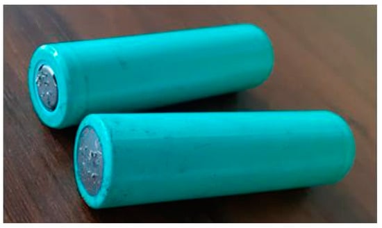
Figure 1.
Lithium-ion battery 18650.
2.2. Machine Element Calculation and Frame Analysis
The magnetic separator design was made with a conveyor concept, and a slot was made on one of the rollers to place the magnet. In this research, a magnetic separator machine was produced by making a magnetic roller, in which a slot was inserted to place the magnet on the roller. Thus, the need for electricity is only to rotate the drive motor, and finally, it will drive the rollers. The components of this method are also not too expensive.
The best way to minimize production costs is to recognize the importance of manufacturing at the design stage [16]. Design for Manufacture and Assembly (DFMA) is a brief guide launched by Bart Huthwaite, Director of the Institute for Competitive Design, Rochester, USA. DFMA is used to reduce assembly costs, simplify design, increase product reliability, and reduce operating times [16].
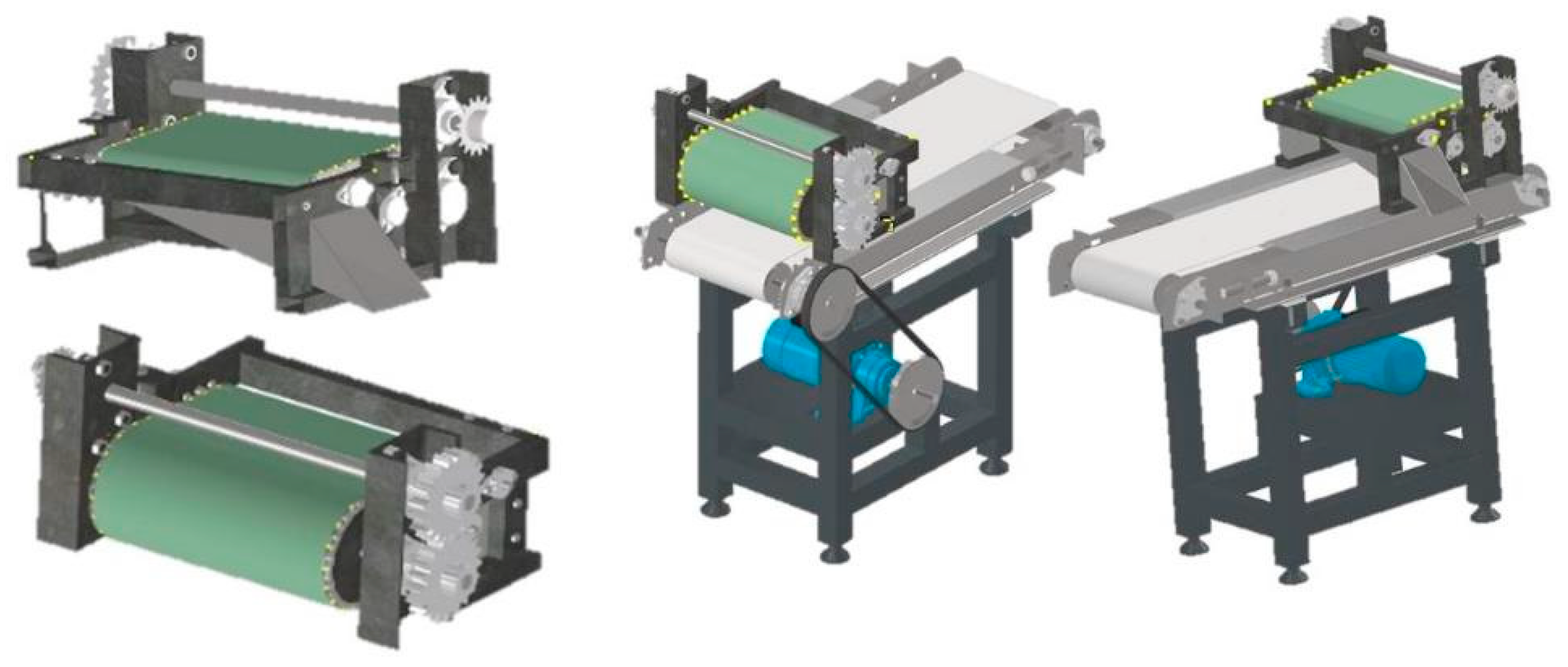
Autodesk Inventor Professional 2022 software was used in the three-dimensional design of this magnetic separator machine. This process was carried out several times with design optimization to obtain an effective and efficient design. The final design of the magnetic separator machine can be seen in Figure 2. Machine element calculations were also carried out. The diameter of the shaft and the load on the shaft were calculated using a shear force diagram (SFD) and a bending moment diagram (BMD).

Figure 2.
Final design of the magnetic separator machine.
Computer-Aided Engineering (CAE) is a process of solving engineering problems by utilizing sophisticated interactive graphics software. CAE is a computer system that is used to analyze CAD designs that allow engineers to carry out loading simulations on designed products [17]. An analysis was also carried out on the frame that had been designed in the form of Von Mises stress, maximum shear stress, and total deformation that occur in the frame using Ansys Student 2022 R2.
The material used in this magnetic separator machine is ST37 steel or equivalent to AISI 1045. ST37 steel material has a density of 7.872 g/cm3; besides that, the ultimate tensile strength is 440 MPa and the tensile strength at yield is 370 MPa. The frame uses hollow steel measuring 20 × 40 with a thickness of 2 mm and UNP 10 steel. In this study, a mesh size of 4 mm was used because the Ansys Student 2022 R2 has a maximum of ±125,000 nodes. The authors used an element size of 4 mm because, with the element size, the number of nodes closest to 125,000 is 124,120.
There are 4 shafts in this magnetic separator machine. The first is the shaft with a diameter of 20 mm at the top along with the sprocket and spur gear with a weight of 3.74 Kg. The second is a shaft with a diameter of 20 mm with a magnetic roller along with the weight of the belt and chain with a total weight of 7.455 Kg. The third is a shaft adjuster with a diameter of 10 mm and a weight of 0.75 Kg, and the fourth is a shaft with a diameter of 10 mm with a non-magnetic roller and a weight of 1.026 Kg. The weight of this part is then multiplied by the acceleration of gravity with a value of ±10 m/s2.
3. Result and Discussion
In Figure 3, it can be seen that the magnetic separator machine works by passing the lithium-ion battery enumeration under the magnetic roller so that magnetic materials can be attracted to the magnetic roller. The magnetic separator machine shaft is connected to the conveyor shaft to drive the magnetic roller, but because of the opposite rotation of the conveyor shaft and the magnetic separator machine shaft, it needs a countershaft from the conveyor shaft so that the rotation of the magnetic roller shaft can match the desired design. The separated material is then directed by a funnel to the container. A belt conveyor is used to distribute the separated material; in general, a belt on the conveyor often shifts to the right or left when it is operated, so in this design, the belt is connected to the conveyor chain so that the belt that has been installed will not be able to move to the right or left.

Figure 3.
Magnetic separator’s working principle.
3.1. Calculating the Shear Force Diagram (SFD) and Bending Moment Diagram (BMD)
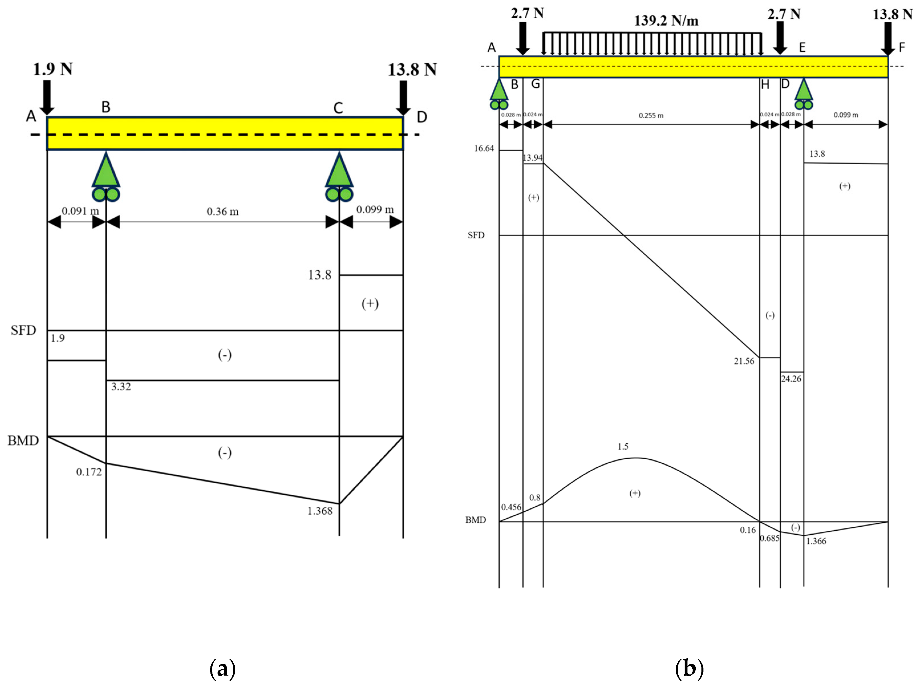
SFD and BMD calculations were carried out to calculate the load experienced by the shaft with a certain length. This calculation was carried out on the shaft used in the magnetic separator machine, which is a shaft with a diameter of 20 mm on the top and magnetic roller, and then there is also a 10 mm diameter shaft on the adjuster and non-magnetic roller.
In Figure 4, it can be seen that in the shaft with a diameter of 20 mm on the top (a), the largest shear force is 17.12 N, while the largest bending moment is 1.368 Nm. On the shaft with a diameter of 20 mm with a magnetic roller (b), the largest shear force is 38.06 N at point E, while the largest bending moment is 1.5 Nm at a distributed load on the G−H segment.
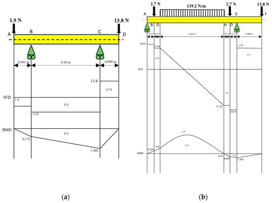
Figure 4.
Calculation of SFD and BMD on (a) the shaft with a diameter of 20 mm on the top and (b) the shaft with a diameter of 20 mm on the magnetic roller.
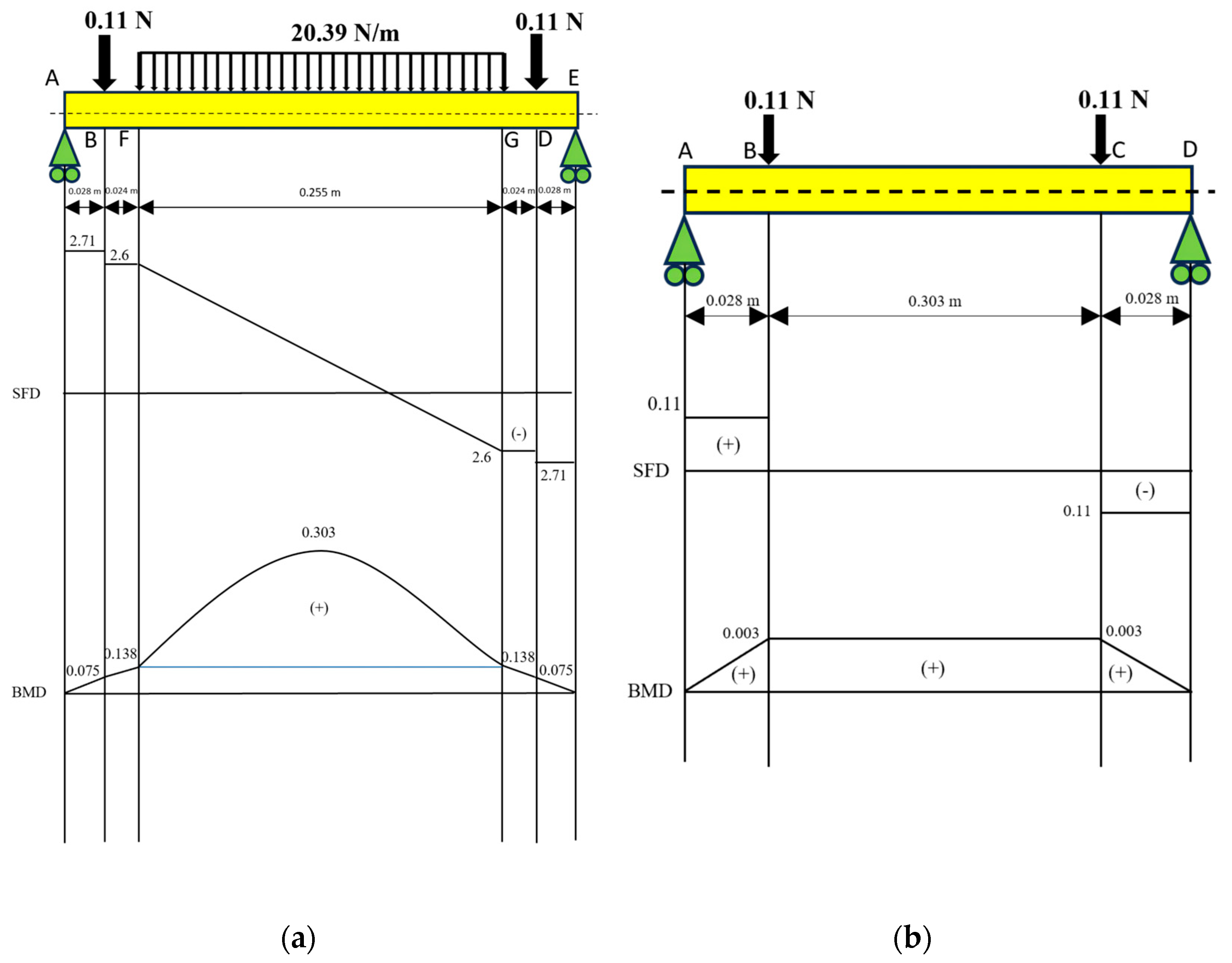
In Figure 5, it can be seen that for the shaft adjuster with a diameter of 10 mm (a), the largest shear force is 0.11 N, while the largest bending moment value is 0.003 Nm. On the shaft diameter of the 10 mm non-magnetic roller (b), the largest shear force is 5.2 N on the distributed load at the F−G segment, while for the largest bending moment, it is 0.303 Nm on the distributed load at the F−G segment.
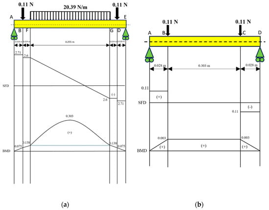
Figure 5.
Calculation of SFD and BMD on (a) the shaft adjuster with a diameter of 10 mm and (b) the shaft with a diameter of 10 mm with the non-magnetic roller.
3.2. Calculating the Diameter of the Shaft
The shaft used in the magnetic separator is a shaft with a torsional moment correction factor (Kt) = 1. In calculating the diameter of the shaft starting by reviewing the torsion moment, this factor is expressed by Kt. The torsional moment value is determined from the torsional moment correction factor, which can be seen in Table 1 [18].

Table 1.
Torsion moment correction factor.
Although in the temporary estimate, the load only consists of torsional moments, it is also necessary to review whether there is a possibility of use with bending loads in the future; the bending factor (Cb) can be seen in Table 2 [18].
Table 2.
Bending factor.
The design torsion moment (T) = 2504.5 kg.mm on the 20 mm shaft and (T) = 607.16 kg.mm on the 10 mm shaft, and the allowable shear stress (τα) = 6.66/mm2. To calculate the diameter of the shaft, we can use the following equation [18]:
The minimum shaft diameter allowed for the magnetic roller shaft (large shaft) is 17.918 mm; in practice, the shaft used is 20 mm and the pillow block bearing is also adjusted to the shaft diameter of 20 mm. In the calculation of the small diameter shaft used in the non-magnetic roller and adjuster shaft, the minimum permitted shaft diameter is 8.455 mm; in practice, the shaft used is 10 mm, so the shaft is safe to use.
3.3. Static Structural Frame Analysis
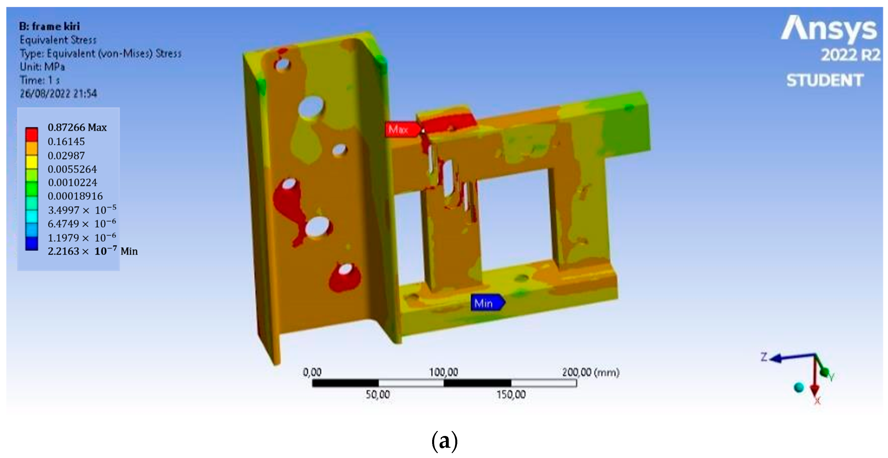
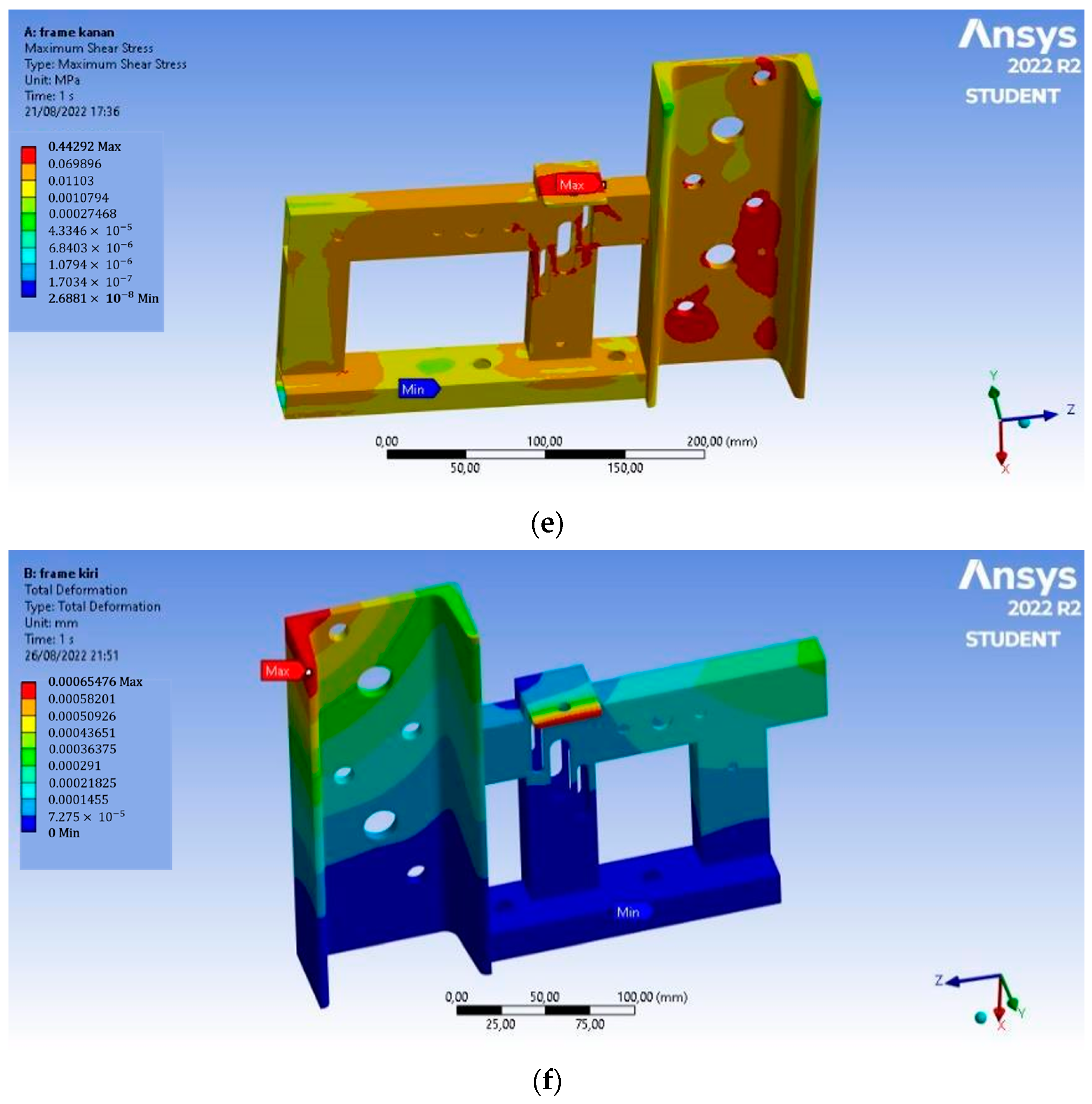
Static structural simulation aims to perform a virtual assessment of the magnetic separator frame components that have been previously designed. In this static structural frame simulation, several analyses were carried out, such as Von Mises stress, total deformation, and maximum shear stress.
In Figure 6, based on the analysis, the Von Mises stress of the left frame has a maximum value of 0.872 MPa, the maximum shear stress that occurs is 0.444 MPa, and the total deformation is 6.5 × 10⁻⁴ mm. This deformation occurs at the end of the chain adjuster. On the right frame, the Von Mises stress has a maximum value of 0.867 MPa, the maximum shear stress that occurs is 0.443 MPa, and the total deformation is 6.6 × 10⁻⁴ mm. This deformation occurs at the end of the chain adjuster, and the value is so small that the magnetic separator frame is safe to use.
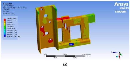
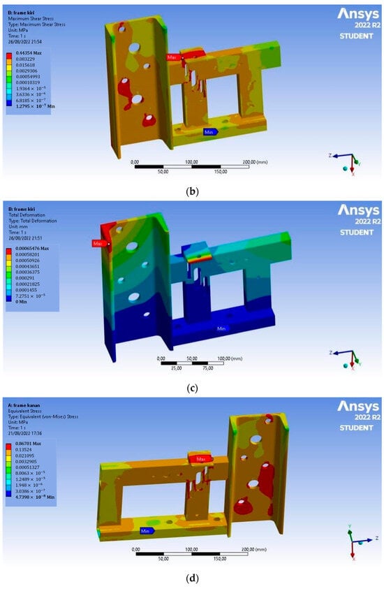

Figure 6.
Static structural analysis: (a) Von Mises stress on the left frame, (b) maximum shear stress on the left frame, (c) total deformation on the left frame, (d) Von Mises stress on the right frame, (e) maximum shear stress on the right frame, and (f) total deformation on the right frame.
4. Conclusions
Based on the design of the magnetic separator machine from the lithium-ion battery enumeration, which includes calculations, modeling, and analysis, the conclusions obtained are as follows:
- The design of the magnetic separator machine is formulated with a conveyor performance system. The crushed material is then transferred by a conveyor for further processing; at the end of the conveyor, a magnetic separator is placed to separate the magnetic materials from the lithium batteries enumeration.
- This magnetic separator machine shaft is connected to a rotating shaft conveyor, so it does not need an additional motor to drive the machine.
- The placement of the belt on the magnetic separator machine is linked to the chain conveyor because the belt will easily change lanes if it is not linked to the chain.
- Based on the power calculation, the required shaft diameter for the magnetic roller shaft is 17.918 mm, and for the non-magnetic roller shaft, it is 8.455 mm. In this design, the authors used a diameter of 20 mm for the magnetic roller shaft, and for the non-magnetic roller shaft, a diameter of 10 mm was used.
- The results of the static structural simulation on the magnetic separator machine frame are safe and worthy of being used in the lithium battery recycling process with stress that does not exceed the yield limit of the material used.
Author Contributions
Conceptualization, M.A.M. and M.R.N.A.; methodology, Y.T.W., I.P., M.M. and B.A.; software simulation; M.R.N.A. and Y.T.W.; investigation, E.F., M.M., B.A. and I.P.; validation, E.F., M.M., B.A, I.P. and M.A.M.; visualization, M.R.N.A. and Y.T.W.; data curation, E.F., M.R.N.A. and Y.T.W.; writing—original draft preparation M.R.N.A., Y.T.W. and M.A.M.; writing—review and editing Y.T.W., M.A.M., M.M., B.A. and I.P.; supervision, M.A.M.; project administration M.A.M.; funding acquisition, I.P. and M.A.M. All authors have read and agreed to the published version of the manuscript.
Funding
This research was funded by Lembaga Pengelola Dana Pendidikan (LPDP) grant number PRJ-77/LPDP/2020 and The APC was funded by LPDP.
Institutional Review Board Statement
Not applicable.
Informed Consent Statement
Not applicable.
Data Availability Statement
Data are available from the authors upon request.
Acknowledgments
We would like to express our deepest gratitude to Lembaga Pengelola Dana Pendidikan (LPDP) for their support. Additionally, we extend our appreciation to Gadjah Mada University (UGM) for their valuable contributions.
Conflicts of Interest
The authors declare no conflicts of interest.
References
- Zhai, P.; Liu, K.; Wang, Z.; Shi, L.; Yuan, S. Multifunctional separators for high-performance lithium-ion batteries. J. Power Sources 2021, 499, 229973. [Google Scholar] [CrossRef]
- Gaines, L. Lithium-ion battery recycling processes: Research towards a sustainable course. Sustain. Mater. Technol. 2018, 17, e00068. [Google Scholar] [CrossRef]
- Recycle Spent Batteries; Nature Publishing Group: London, UK, 2019. [CrossRef]
- Li, J.; Zhang, Y.; Shang, R.; Cheng, C.; Cheng, Y.; Xing, J.; Wei, Z.; Zhao, Y. Recent advances in lithium-ion battery separators with reversible/irreversible thermal shutdown capability. Energy Storage Mater. 2021, 43, 143–157. [Google Scholar] [CrossRef]
- Tan, J.; Wang, Q.; Chen, S.; Li, Z.; Sun, J.; Liu, W.; Yang, W.; Xiang, X.; Sun, X.; Duan, X. Recycling-oriented cathode materials design for lithium-ion batteries: Elegant structures versus complicated compositions. Energy Storage Mater. 2021, 41, 380–394. [Google Scholar] [CrossRef]
- Wibisono, F.A.; Mahardika, M.; Arifvianto, B.; Fismatika, A.T.; Muflikhun, M.A. A simulation of the comminution process of homogenized lithium-ion battery models. J. Mech. Sci. Technol. 2022, 36, 3361–3372. [Google Scholar] [CrossRef]
- Sommerville, R.; Shaw-Stewart, J.; Goodship, V.; Rowson, N.; Kendrick, E. A review of physical processes used in the safe recycling of lithium-ion batteries. Sustain. Mater. Technol. 2020, 25, e00197. [Google Scholar] [CrossRef]
- Zhan, R.; Pan, L. A cycling-insensitive recycling method for producing lithium transition metal oxide from Li-ion batteries using centrifugal gravity separation. Sustain. Mater. Technol. 2022, 32, e00399. [Google Scholar] [CrossRef]
- Barbosa, J.C.; Reizabal, A.; Correia, D.M.; Fidalgo-Marijuan, A.; Gonçalves, R.; Silva, M.M.; Lanceros-Mendez, S.; Costa, C.M. Lithium-ion battery separator membranes based on poly (L-lactic acid) biopolymer. Mater. Today Energy 2020, 18, 100494. [Google Scholar] [CrossRef]
- Diekmann, J.; Hanisch, C.; Froböse, L.; Schälicke, G.; Loellhoeffel, T.; Fölster, A.S.; Kwade, A. Ecological Recycling of Lithium-Ion Batteries from Electric Vehicles with Focus on Mechanical Processes. J. Electrochem. Soc. 2017, 164, A6184–A6191. [Google Scholar] [CrossRef]
- Widijatmoko, S.D.; Gu, F.; Wang, Z.; Hall, P. Selective liberation in dry milled spent lithium-ion batteries. Sustain. Mater. Technol. 2020, 23, e00134. [Google Scholar] [CrossRef]
- Jin, S.; Mu, D.; Lu, Z.; Li, R.; Liu, Z.; Wang, Y.; Tian, S.; Dai, C. A comprehensive review on the recycling of spent lithium-ion batteries: Urgent status and technology advances. J. Clean. Prod. 2022, 340, 130535. [Google Scholar] [CrossRef]
- Bernardes, A.M.; Espinosa, D.C.R.; Tenório, J.A.S. Recycling of batteries: A review of current processes and technologies. J. Power Sources 2004, 130, 291–298. [Google Scholar] [CrossRef]
- Makuza, B.; Tian, Q.; Guo, X.; Chattopadhyay, K.; Yu, D. Pyrometallurgical options for recycling spent lithium-ion batteries: A comprehensive review. J. Power Sources 2021, 491, 229622. [Google Scholar] [CrossRef]
- Yu, D.; Huang, Z.; Makuza, B.; Guo, X.; Tian, Q. Pretreatment options for the recycling of spent lithium-ion batteries: A comprehensive review. Miner. Eng. 2021, 173, 107218. [Google Scholar] [CrossRef]
- Bhandari, V.B. Design of Machine Elements, 3rd ed.; Tata McGraw Hill Education Private Limited: New Delhi, India, 2010. [Google Scholar]
- Boothroyd, G.; Dewhurst, P.; Knight, W.A. Product Design for Manufacture and Assembly, 3rd ed.; CRC Press: Boca Raton, FL, USA, 2011. [Google Scholar]
- Logan, D.L. A First Course in the Finite Element Method; Cengage Learning: Boston, MA, USA, 2017. [Google Scholar]


Disclaimer/Publisher’s Note: The statements, opinions and data contained in all publications are solely those of the individual author(s) and contributor(s) and not of MDPI and/or the editor(s). MDPI and/or the editor(s) disclaim responsibility for any injury to people or property resulting from any ideas, methods, instructions or products referred to in the content. |
© 2025 by the authors. Licensee MDPI, Basel, Switzerland. This article is an open access article distributed under the terms and conditions of the Creative Commons Attribution (CC BY) license (https://creativecommons.org/licenses/by/4.0/).