Abstract
Micro-electro-mechanical system (MEMS) gas flowmeters are innovative devices that use microfabrication technology to measure gas flow with high precision and sensitivity. With MEMS technology, flow measurement can now be performed more accurately and compactly than ever, using low-power, compact, and highly accurate sensors. MEMS gas flowmeters utilize various principles to measure gas flow, including thermal, Coriolis, and pressure differential methods. A micro-flowmeter was developed by combining a MEMS sensor with a weak signal acquisition technique. High heat isolation and sensitivity can be achieved using a MEMS sensor with a thermal resistor-suspended VO2 structure. Since SU-8 gum is used for the flow channel, the technology is simple and affordable, making it suitable for batch production. To acquire high-resolution, low-noise data, the device uses a super low bias current operational amplifier, aided by guard ring protection, and a 24-bit high-resolution ADC. The sensor and data acquisition combination shows that the flowmeter has favorable linearity and sensitivity between 0 and 50 mL/min at a specific offset voltage. Biochemical detection and medicine require a high-sensitivity, high-stability, and low-cost flowmeter.
1. Introduction
A MEMS comprises a microsensor, DSP, power, and a specific function. Due to its small volume, low power consumption, and delicate operation, nanoscience is becoming increasingly dependent on this technology [1]. In fields like biochemistry and medicine, flow sensors must be able to operate at high precision, at minimal volume, and with a very short response time since flow rates generally range from L/min to mL/min. During the past few years, there has been an increasing interest in flow sensors based on MEMS technology because of their inherent characteristics [2]. Innovative MEMSs for underwater applications and communication systems have been reported [3,4,5,6,7,8,9,10,11,12].
To detect tiny flows, signal acquisition systems in this type of flowmeter should have high resolution, for example, 0.01 mL/min. Thus, designing a signal acquisition system that is low-noise and high-resolution is essential. This paper proposes the design and fabrication of a micro gas flow sensor using the MEMS technique and the design and fabrication of a low-noise, high-resolution signal acquisition system, which directly correlates with the sensor’s output. The flowmeter must possess some specific advantages, such as high sensitivity and stability, to satisfy the needs of the applications in biochemical detection and medicine. Furthermore, it should also be cost-effective.
2. Overall Design
Figure 1 illustrates the overall structure of the micro-flowmeter system. The MEMS sensor produces a weak voltage signal depending on the gas flow (Figure 2). A high-resolution ADC is used to sample the weak voltage signal, after which a low-noise operational amplifier amplifies it, and the amplitude of the signal is then acquired by the MCU, which in turn is used to calculate the corresponding flow velocity based on the sampled signal. Using a serial port or an LCD display, the measurement results can be displayed and transferred to the underlying computer to simultaneously display the curves for the measurements.
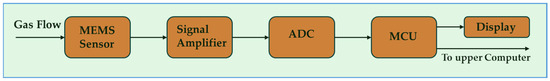
Figure 1.
Micro-flowmeter system structure.
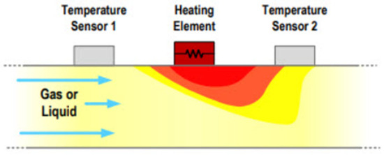
Figure 2.
Micro-flowmeter system structure.
Flowmeters represent the instrumentation of flow sensors and are used to measure the amount of flow that passes through them. There are in principle five different flowmeter types: velocity flow, positive displacement flow, differential pressure flow, open channel flow, and mass flow. Gas flowmeters are one of the dominant types due to their faster response and better accuracy than other flowmeters. They can also be effectively miniaturized and manufactured on silicon wafers. The emergence of MEMSs has already revolutionized the consumer electronics market for motion, pressure, and other sensors, and similar micro-machining processes are now being adapted to fabricate flow sensors. Flow sensing applications are typically high-mix and low-to-medium-volume compared, for example, to motion sensors that have become ubiquitous in hundreds of millions of smartphones. This novel MEMS gas flowmeter with a temperature difference suspension structure is designed to achieve high sensitivity, low power consumption, and precision in measuring gas flow rates.
3. Sensor Design
3.1. Operational Principle of Sensor
In differential calorimetric flow sensors, thermal resistors are placed on both ends. During gas flow, the heat distribution map created by the heat source moves, which changes the resistance of the upper and lower resistors. Based on this change, the gas flow velocity can be calculated. Usually, a Wheatstone bridge is used to perform the estimation, as shown in Figure 3 [13].
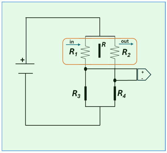
Figure 3.
Schematic representation of Wheatstone bridge.
This demonstrates [14] that determining the output voltage of a bridge is a complex function that includes parameters for flow velocity, structure, and material characteristics.
3.2. Fabrication Process
Two thermal resistors are suspended in a flow channel in this flow sensor, forming a thermal resistor-suspended structure. Unlike conventional structures, this structure has no conduction from the base, which makes it highly effective at isolating heat. Consequently, it has a high degree of sensitivity and rapid response time. In addition, 3R and 4R are precision resistors that remain stable regardless of temperature. We chose VO2, which has a high resistor temperature coefficient, to prepare thermal resistors with a higher sensitivity. Due to VO2’s temperature coefficient of −3.4 × 10⁻² K−1~4 × 10⁻² K−1 (Pt’s TCR is −3.9 × 10⁻³ K−1), the output voltage increases, resulting in a higher sensitivity. Aside from that, VO2 is chemically inert, making it ideal for the stabilization of sensor electrodes [15]. Figure 4 shows the sensor’s MEMS fabrication process.
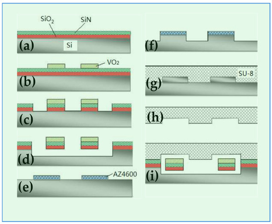
Figure 4.
MEMS fabrication process.
The fabrication process is described below:
a. The oxide layer of SiO2 is deposited on the silicon base. LPCVD is then used to deposit a layer of Si3N4 as the thermal resistor-bearing beam.
b. The thermal resistor graph will appear after exposure.
c. After lifting off, VO2 is deposited and the thermal resistors are obtained.
d,e. Photolithography is used to fabricate the flow channel graphic, which is covered with a positive photoresist. The thermal resistors are released by combining mechanical erosion and corrosion with KOH.
f. To obtain the SU-8 gum mold graph, the silicon chip is covered with AZ4600 gum.
g. By mechanical deep erosion, the SU-8 gum mold is obtained.
h. After the SU-8 gum has solidified, microchannels are generated.
i. The microchannels in the SU-8 gum should be aligned with those in the silicon chips.
4. Acquisition System Design
4.1. Guarding of Amplifying Circuit
The amplifier’s gain and noise performance affect measurements’ precision and resolution. Here, we use a low-biased current amplifier, the LMP7721. In addition to a bias current limited to ±20fA, the amplifier also possesses an offset voltage below 26 uV [16]. As a result of pollution or humidity, PCB resistivity decreases. Thus, leakage current will occur at the input point due to potential differences between the input and other stations, which cannot be ignored when detecting weak signals. Problems like this can be solved with the guard method. A guard is present at the sensitive node. It comprises a low-impedance conductor with a potential raised to match the node’s voltage. The guard ring passes the leakage current to the analog ground without interfering with the input [17]. To prevent leakage currents, the LMP7721 needs to be fully guarded.
4.2. High-Resolution ADC
It is necessary to have a high-precision ADC to acquire high-precision signals. Here, we used the ADS1211, a four-channel, 24-bit high-precision ADC manufactured by B.B. Corporation (Tucson, AZ, USA). ADS1211’s effective resolution is 20 bits, and a low-noise programmable gain amplifier further enhances the dynamic range [18]. For 5V, the theoretical resolution would be 5000/220 = 0.005 mV.
4.3. Power and Layout
Power supplies, DC-DC ICs, and disturbances from digital to analog supplies generate considerable power noise. DC-DC ICs and batteries with low noise are recommended to attenuate this type of noise. Separate power should be provided for analog and digital components. A disturbance is isolated by placing an inductor between the AVDD and DVDD if only one power supply is used [19].
In addition to the arrangement and wiring of the PCB, these factors strongly influence the noise of the acquisition system. First, analog and digital devices should be arranged separately. Second, there should be sufficient width between power lines to prevent the spread of resistance and inductance. Lastly, the grounds for the digital and analog parts must be laid separately and then connected via magnetic beads.
5. Experiment Results and Analysis
Figure 5 shows the velocity–output curve when the offset voltage is 10 V, 12 V, and 14 V. The increased output voltage from a higher offset voltage enhances sensitivity in the 1~50 mL/min range. The linearity range, however, decreases as the offset voltage increases. If an offset voltage of 14V is applied, the linear range increases to 25 mL/min.
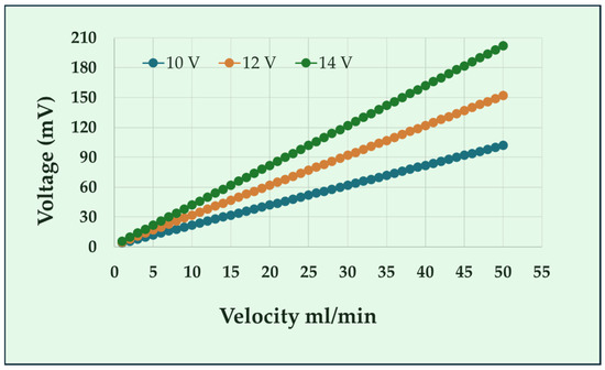
Figure 5.
A comparison of response characteristics under different offsets.
6. Conclusions
This paper describes the design of a micro-flowmeter that includes a sensor and a data acquisition module. As a flow sensor, this device is fabricated through MEMS technology, with a thermal resistor suspended in its structure. It also has excellent temperature isolation capabilities. SU-8 gum is used in the flow. In addition to being simple, highly stable, and suitable for bulk production, this technology is also cost-effective. The weak signal is amplified by a super low bias current operational amplifier, LMP7721, combined with a guard ring. Data are acquired using the 24-bit ADS1211 manufactured by B.B. Company. It is necessary to separate analog from digital parts, ground them separately, and isolate disturbances from digital to analog. The data acquisition and sensor combination indicates that the flowmeter is linear and sensitivity-conforming in the range of 0-50mL/min at a suitable offset voltage. As a result, it is suitable for biochemical detection, medicine, etc., providing good prospects for promotion.
Author Contributions
Conceptualization, B.A. and A.Q.; methodology, B.A.; software, B.A. and A.Q.; validation, B.A., A.Q. and A.R.A.; formal analysis, A.R.A.; investigation, B.A.; resources, B.A.; data curation, B.A. and A.R.A.; writing—original draft preparation, B.A.; writing—review and editing, B.A., A.Q. and A.R.A.; visualization, A.Q.; supervision, B.A.; project administration, B.A. All authors have read and agreed to the published version of the manuscript.
Funding
This research received no external funding.
Institutional Review Board Statement
Not applicable.
Informed Consent Statement
Not applicable.
Data Availability Statement
The data presented in this study are available within the article and are presented in every graph. There are no more data apart from those presented.
Conflicts of Interest
The authors declare no conflicts of interest.
References
- Huang, L. Micromachined Thermal Time-of-Flight Flow Sensors and Their Applications. Micromachines 2022, 13, 1729. [Google Scholar] [CrossRef] [PubMed]
- Löfdahl, L.; Gad-El-Hak, M. MEMS applications in turbulence and flow control. Prog. Aerosp. Sci. 1999, 35, 101–203. [Google Scholar] [CrossRef]
- Abdul, B.; Mastronardi, V.; Qualtieri, A.; Guido, F.; Algieri, L.; Rizzi, F.; De Vittorio, M. Design, fabrication and characterization of piezoelectric cantilever MEMS for underwater application. Micro Nano Eng. 2020, 7, 100050. [Google Scholar] [CrossRef]
- Abdul, B.; Mastronardi, V.M.; Qualtieri, A.; Algieri, L.; Guido, F.; Rizzi, F.; De Vittorio, M. Sensitivity and Directivity Analysis of Piezoelectric Ultrasonic Cantilever-Based MEMS Hydrophone for Underwater Applications. J. Mar. Sci. Eng. 2020, 8, 784. [Google Scholar] [CrossRef]
- Hodjat-Shamami, M.; Norouzpour-Shirazi, A.; Tabrizian, R.; Ayazi, F. A Dynamically Mode-Matched Piezoelectrically Transduced High-Frequency Flexural Disk Gyroscope. In Proceedings of the 2015 28th IEEE International Conference on Micro Electro Mechanical Systems (MEMS), Estoril, Portugal, 18–22 January 2015; pp. 789–792. [Google Scholar]
- Kashiwao, T.; Izadgoshasb, I.; Lim, Y.Y.; Deguchi, M. Optimization of Rectifier Circuits for a Vibration Energy Harvesting System Using a Macro-Fiber Composite Piezoelectric Element. Microelectron. J. 2016, 54, 109–115. [Google Scholar] [CrossRef]
- Asanuma, H.; Hashimoto, S.; Tano, S.I.; Takashima, S.I.; Nishizawa, M.; Niitsuma, H.; Shindo, Y. Development of Fiber-Optical Microsensors for Geophysical Use. In Proceedings of the 2003 International Conference on Physics and Control, Tokyo, Japan, 25–27 June 2003; p. 315. [Google Scholar]
- Abdul, B. Development of a Novel Silicon Membrane MEMS Capacitive Pressure Sensor for Biological Applications. Eng. Proc. 2023, 48, 54. [Google Scholar] [CrossRef]
- Tsai, J.M.; Daneman, M.; Boser, B.; Horsley, D.; Tang, H.Y.; Lu, Y.; Rozen, O.; Liu, F.; Lim, M.; Assaderaghi, F. Versatile CMOS-MEMS Integrated Piezoelectric Platform. In Proceedings of the 18th International Conference on Solid-State Sensors, Actuators and Microsystems (Transducers), Alaska, AK, USA, 21–25 June 2015; pp. 2248–2251. [Google Scholar]
- Yang, J.; Zhang, M.; Si, C.; Han, G.; Ning, J.; Yang, F.; Wang, X. A T-Shape Aluminum Nitride Thin-Film Piezoelectric MEMS Resonant Accelerometer. J. Microelectromech. Syst. 2019, 28, 776–781. [Google Scholar] [CrossRef]
- Asary, A.R.; Abdul, B.; Samad, A.; Shibly, M.A.H. Enhancing Gamma Stirling Engine Performance through Genetic Algorithm Technique. Eng. Proc. 2023, 56, 29. [Google Scholar] [CrossRef]
- Sadiq, H.; Sadiq, H.; Sohail, A.; Basit, A.; Akhtar, N.; Batool, K.; Hisaindee, S.; Asghar, L. Assessment of antioxidant activity of pure graphene oxide (GO) and composite V2O5/GO using DPPH radical and H2O2 scavenging assays. J. Sol-Gel Sci. Technol. 2023, 108, 840–849. [Google Scholar] [CrossRef]
- Kuo, J.T.W.; Yu, L.; Meng, E. Micromachined Thermal Flow Sensors—A Review. Micromachines 2012, 3, 550–573. [Google Scholar] [CrossRef]
- Nguyen, N.; Dötzel, W. Asymmetrical locations of heaters and sensors relative to each other using heater arrays: A novel method for designing multi-range electrocaloric mass-flow sensors. Sens. Actuators A Phys. 1997, 62, 506–512. [Google Scholar] [CrossRef]
- Wang, L.; Li, J. Fabrication of Vanadium Dioxide Films at Low Temperature and Researches on Properties of the Films. Acta Phys. 2006, 55, 2846–2851. (In Chinese) [Google Scholar] [CrossRef]
- National Semiconductor Corporation. 3 Femtoampere Input Bias Current Precision Amplifier LMP7721. 2008. Available online: https://web.archive.org/web/20110923162742/http://www.national.com/ (accessed on 23 July 2024).
- Sorokin, B.P.; Kvashnin, G.M.; Volkov, A.P.; Bormashov, V.S.; Aksenenkov, V.V.; Kuznetsov, M.S.; Gordeev, G.I.; Telichko, A.V. AlN/Single Crystalline Diamond Piezoelectric Structure as a High Overtone Bulk Acoustic Resonator. Appl. Phys. Lett. 2013, 102, 10–13. [Google Scholar] [CrossRef]
- Burr-Brown Corporation. 24-Bit ANALOG-TO-DIGITAL CONVERTER ADS1211[R]. 2007. Available online: http://www.burr-brown.com (accessed on 23 July 2024).
- Montrose Mark, I. Printed Circuit Board Design Techniques for EMC; Wiley-IEEE Press: Hoboken, NJ, USA, 2010. [Google Scholar]
Disclaimer/Publisher’s Note: The statements, opinions and data contained in all publications are solely those of the individual author(s) and contributor(s) and not of MDPI and/or the editor(s). MDPI and/or the editor(s) disclaim responsibility for any injury to people or property resulting from any ideas, methods, instructions or products referred to in the content. |
© 2025 by the authors. Licensee MDPI, Basel, Switzerland. This article is an open access article distributed under the terms and conditions of the Creative Commons Attribution (CC BY) license (https://creativecommons.org/licenses/by/4.0/).