Proceeding Paper

Untethered Flight of a 5 cm Micro Vehicle Powered by an Onboard Capacitor †

Chinese Aeronautical Establishment, Beijing 100012, China
*
Author to whom correspondence should be addressed.
Presented at the 2nd International Conference on Green Aviation (ICGA 2024), Chengdu, China, 6–8 November 2024.
Eng. Proc. 2024, 80(1), 8; https://doi.org/10.3390/engproc2024080008
Published: 2 January 2025
(This article belongs to the Proceedings of 2nd International Conference on Green Aviation (ICGA 2024))

Abstract

:
Due to the small size of the micro aircraft, it has high permeability and concealability, holding promise in application in the military and civil fields, and it has become a domestic and international research frontier and hotspot in the past decade. However, caused by the heavy onboard power supply and the decline in the actuator’s operating power at micro sizes, untethered flight is still a development difficulty at present. In this paper, we introduce a new micro vehicle configuration which is driven by onboard capacitive energy and can realise off-line free flight under the drive of electrostatic actuators. In the overall design, this paper proposes structural capacitors as the energy supply unit and buoyancy unit of the vehicle, which can overcome part of the vehicle body’s weight by being filled with helium gas, while the capacitor can provide electrical energy for the propulsion unit. The micro vehicle has a wingspan of 5 cm, a total mass of 165 mg, a stable operating voltage between 1300 V and 2400 V, and a flight time of more than 60 s under the condition of an onboard capacitor power supply. The micro vehicle designed in this thesis has a small wingspan, light weight, and better concealment, and it has broad application prospects in the future in environmental reconnaissance, surveying, and other scenarios.

1. Introduction

It is highly difficult to realise off-line flight using onboard energy for micro air vehicles (with a wingspan of less than 15 cm) due to the large relative mass of the onboard energy [1,2,3]. In recent years, due to the promising progress of micro-electronics, several bionic vehicles with high concealment and high permeability have become research hotspots, attracting many scholars to carry out research related to micro-vehicles.
Currently, bionic vehicles above 15 cm in size are mainly driven by electromagnetic motors. For example, some bionic vehicles [4,5] look like hummingbirds, and combined with micro onboard devices, they can achieve stable controlled flight, roving surveillance, image recognition, and other diversified functions [6,7,8,9,10]. In addition, there are some micro-vehicles which can achieve multi-degree-of-freedom movement in complex environments [11,12,13] with the motion abilities of land-air, land-water, or water-air. The tiny size and biomimetic appearance give these vehicles better concealment and movement ability, which have broad application prospects in reconnaissance and survey scenarios [14,15]. However, with the size reduction, limited by the scale effect, this leads to the electromagnetic motor having problems with output power decline, serious heat generation, and high noise. It is difficult to achieve microminiature and lightweight bionic vehicles (5–6 cm level or milligram level). Therefore, in practical applications, it is desirable to have vehicles with the smallest structures possible to achieve better environmental adaptability and concealment. The contradiction between size reduction and insufficient drive power has prompted researchers and scholars to explore novel drive principles.
In recent years, several novel actuators [16,17,18] have been increasingly studied, such as the gel actuator [19], photothermal actuator [20], temperature actuator [21], and electromagnetic actuator [22]. These actuators have better output performance compared with the electromagnetic actuator at tiny sizes and are widely used in the field of micro air vehicles. For example, a bionic micro-vehicle designed at Harvard University utilised the piezoelectric actuator to achieve the first take-off at the 5 cm size [23]. Subsequently, the micro-vehicle has achieved stable controlled flight with the integration of micro-sensors [24,25,26,27,28]. In addition, dielectric elastomer actuators have been used as the power unit for micro air vehicles to achieve stable flight through a ground energy supply [29]. Although the above-mentioned vehicles have achieved stable flight motion, untethered flight motion is still difficult to achieve due to the limitations of onboard energy sources. Currently, there are some vehicles which achieve flight by using wireless energy, such as by using the three sources of sunlight [30,31], ground lasers [32], or microwaves [33]. Although wireless energy transfer can help achieve untethered flight of a vehicle, it requires a complex ground system to transmit a massive amount of energy, and its energy conversion efficiency is low. Therefore, there is still potential in exploring novel configurations to realise untethered flight of micro-vehicles.
In this paper, a micro air vehicle with a wingspan of 5 cm is designed based on the electrostatic principle, and the onboard structural capacitor is designed to realise the energy supply of the vehicle. The structural capacitor serves as both the buoyancy for the vehicle and energy storage for the drive unit. The micro vehicle we designed has a small wingspan and light weight, and it can be used in the future for environmental detection, post-disaster surveys, on-site investigation, and other application prospects. This paper has both academic value and engineering applications, which are of great significance for the development of micro flying vehicles.

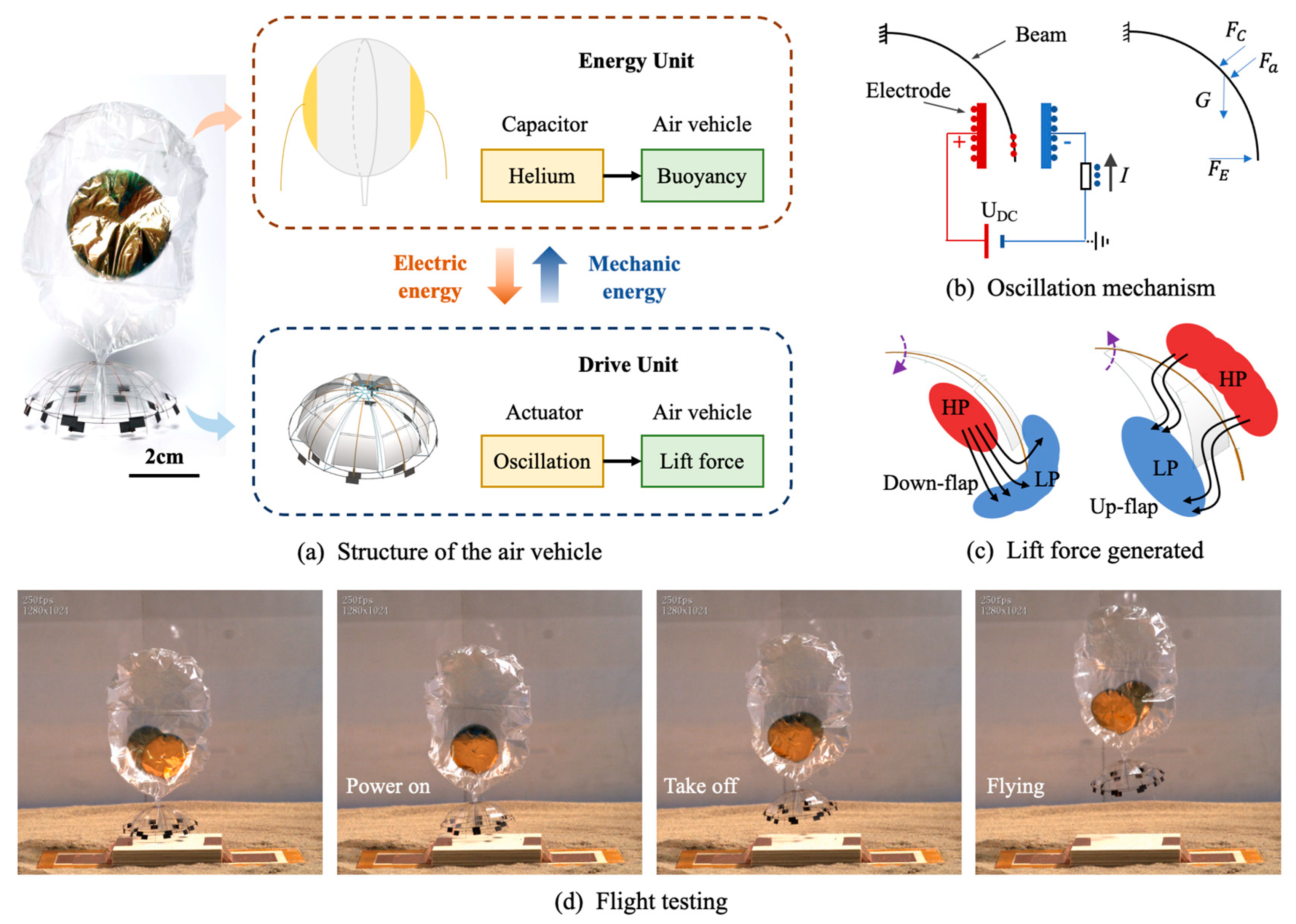
2. General Design of the Air Vehicle
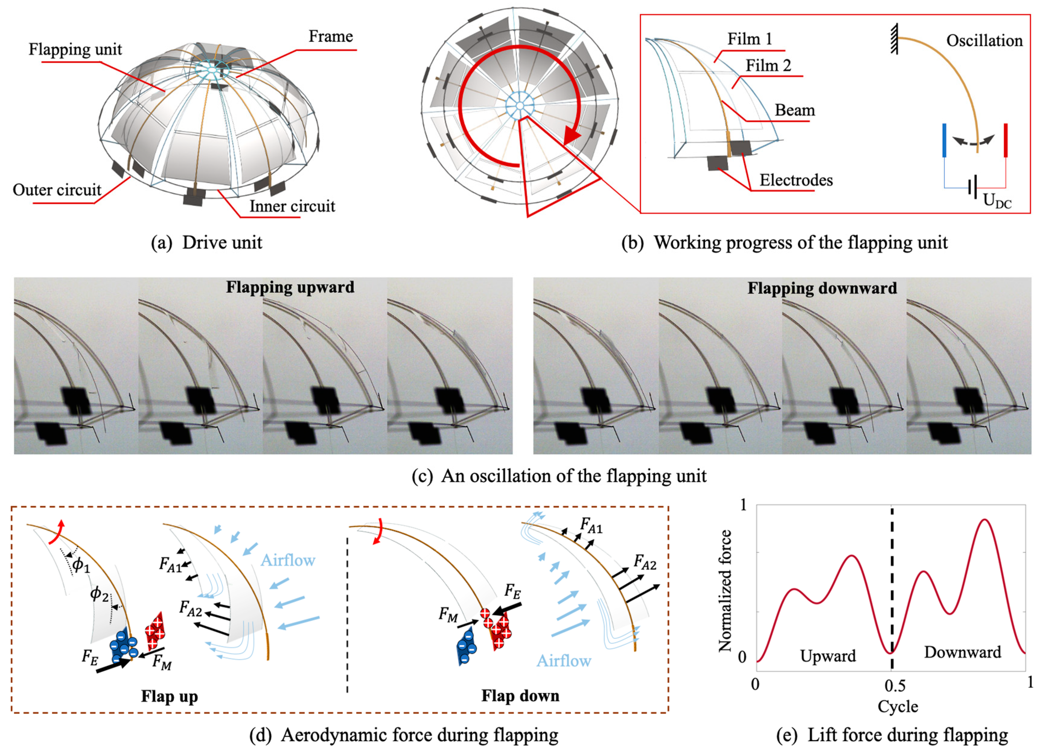
In this paper, we propose a micro-vehicle configuration with a 5 cm wingspan, as shown in Figure 1a, which consists of two parts: an energy unit and a drive unit. The energy unit is fabricated into structural capacitance through the gold coating process, which can provide buoyancy for the micro-vehicle as well as the energy output for the drive unit. The drive unit is designed based on the electrostatic drive principle, whose low power consumption meets the capacitor’s electrical energy output requirements. The beam of the drive unit is designed as a curved configuration, as shown in Figure 1b. Under the action of a high-voltage DC electric field, the electrostatic force FE overcomes the mechanical force Fc and aerodynamic force Fa to oscillate between the electrodes. As shown in Figure 1c, while flapping down, the wing films have a larger aerodynamic cross-sectional area to generate a lift airflow. While flapping up, the airflow makes the wing films rotate, and the aerodynamic cross-sectional area decreases to reduce aerodynamic resistance. The wing films rotating during flapping will result in changes in position of the low-pressure (LP) and high-pressure (HP) regions, generating aerodynamic lift, which is similar to the flapping wings of some insects or birds [34,35,36,37,38]. The aerodynamic forces are generated by a single beam in the vertical direction during flight motion, as shown in Figure 1d. The designed microvehicle has a total mass of 165 mg, a height of 105 mm, a flapping wingspan of 50 mm, and it is powered by an onboard capacitor to achieve untethered flight for more than 60 s.

3. Drive Unit

3.1. Actuator Structural Design
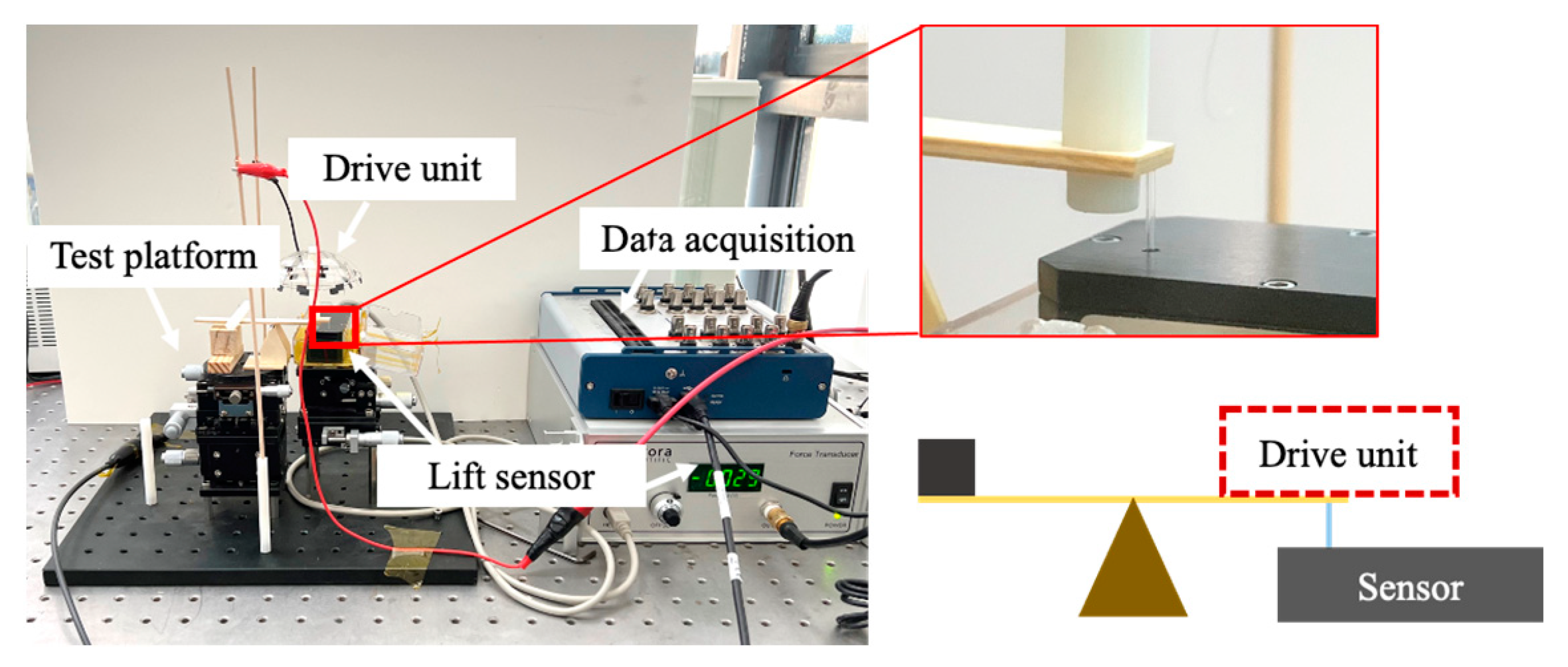
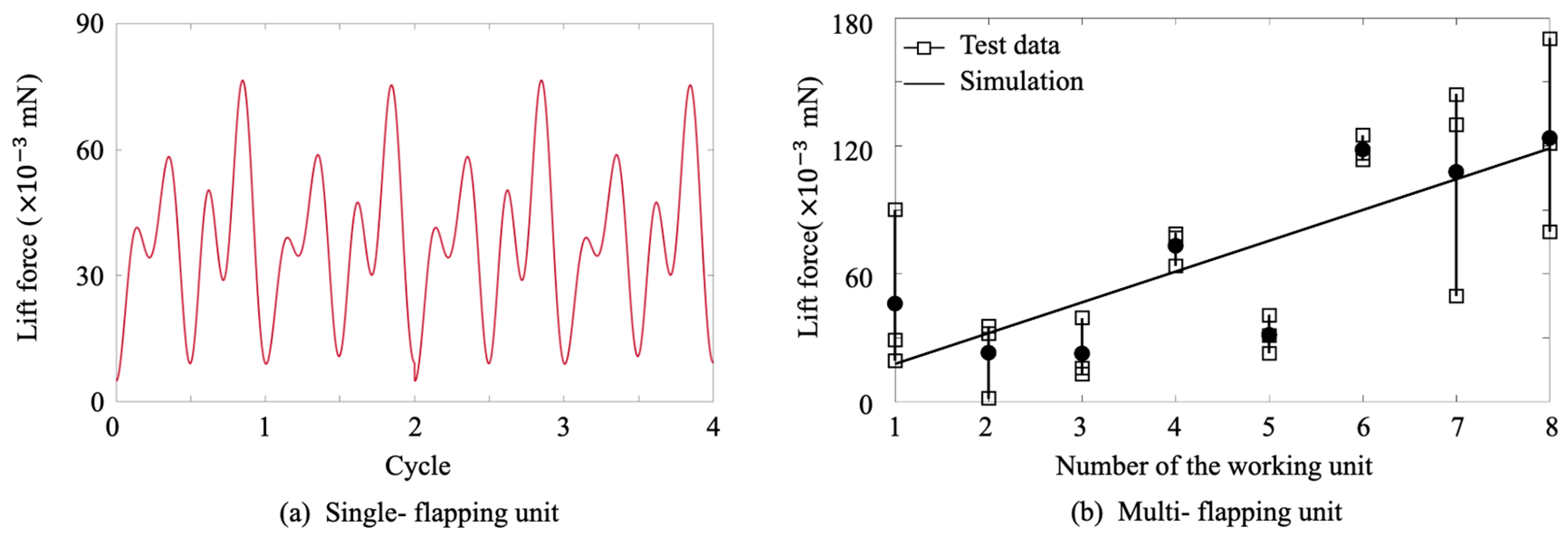
The curved drive unit was inspired by the swimming bell of jellyfish in nature. When the bell contracts, a high-pressure zone is generated inside the cavity, and water is ejected downwards to produce propulsion. When the bell expands, a high-pressure zone forms in the outer cavity, and water gradually fills up the inner cavity. The contraction and expansion phases of jellyfish present asymmetric performance, which makes the contraction faster and thus produces more thrust. While in the contraction process, the cavity deforms slowly. Therefore, airflow will produce a light driving effect. Based on the curved configuration of the jellyfish swimming bell, a curved drive unit was designed. As shown in Figure 2a, the structural components of the propulsion unit include the flapping units, the frame structure, the inner circuit ring, and the outer circuit ring. Among these components, eight beat units are symmetrically distributed in the circumferential direction, and the structure of a single beat unit consists of a metal beam and two wing membranes as well as a pair of electrode plates on the inner and outer circuit rings, as shown in Figure 2b. When a high-voltage DC signal (UDC) is applied to the inner or outer circuit ring, the flapping unit undergoes self-excited vibration between the electrodes, generating a propulsive driving force in the vertical direction.
In this structure design, the reliability of the drive unit will be enhanced due to the distributed propulsion configuration. While working, even if a single beat unit fails, the whole drive unit can still have good working performance. In the structural design of the drive unit, a common loading frame is adopted to reduce the number of parts. The structural design programme includes the following: (1) a flapping unit with a common loading frame to r reduce the quality and (2) a circuit design using the overall inner and outer rings to reduce the complexity of the circuit connections. By simplifying the number of structural components, the complexity of processing and assembly is reduced.
When a DC voltage is applied (2400 V operating voltage in this paper), the beam starts to oscillate, and the electrostatic force FE overcomes the mechanical force FM and the aerodynamic forces FA1 and FA2 (FA1 and FA2 are the combined forces of lift and drag, respectively, generated by the flapping of the wing films), where the lift force is defined as perpendicular to the direction of the airflow and the drag force is defined as that force opposing the flapping direction. During flapping, the beams collide with the electrodes to transfer charges and move in the opposite direction after the collision. In the upward flapping process, wing films 1 and 2 rotate with respect to the beams, generating the rotation angles ϕ 1 and ϕ 2 , respectively. As shown in Figure 2c,d, the relative rotation of the wing films of each unit occurs in the flapping motion, which leads to a change in the positions of the low-pressure and high-pressure regions, similar to some insects or birds. During the downward flap, the attack angle of the film is π / 2 , and thus there is no lift on the wing film (only drag), which leads to positively acting vertical forces. The oscillation of the flapping unit generates effective lift in one cycle as shown in Figure 2e. Due to the rotation of the wing films, the drive unit enhances the lift force during operation.

3.2. Thrust Testing

In this section, the thrust force in the vertical direction of the flapping unit is tested using a microforce measurement sensor (Force Transducer Series 400B, Aurora, ON, Canada) and postprocessing software (National Instrument DAQ Express 5.1, Austin, TX, USA). The test platform is shown in Figure 3, including the drive unit, data acquisition, lift sensor, and test platform, in which the drive unit output the thrust force to the sensor through a lever and the test platform and lift sensor were connected to the ground to avoid damage due to electrical breakdowns caused by accidental high-voltage short connections. After the test, data acquisition and post-processing were carried out to obtain the thrust values (shown in Figure 4 and listed in Table 1) with the increase in the number of flapping unit and the lift force’s approximate linear increase.
As shown in Figure 4a, the force of a single unit was measured, and it produced periodic lift output under the power of high-voltage DC, with an average lift of 0.032 mN. As shown in Figure 4b, the total force of the drive unit exhibited an approximate linear increase with an increase in the unit number. The output phase generated a periodic oscillating force caused by the output phase. In the experimental test, the electrostatic adsorption effect would also cause numerical oscillation, especially in a dry environment, where the effect would be more intense. The numerical sampling error was effectively reduced by grounding the platform, controlling the air humidity, and averaging the data from multiple measurements. The total thrust of the drive unit was measured, and the maximum power consumption, thrust-to-weight ratio, and thrust-to-power ratio could be obtained. The drive unit had a low power consumption level of 10−4 W, which was one order of magnitude lower than those of the piezoelectric actuator and dielectric elastomer actuator and four orders of magnitude lower than that of the electromagnetic motor.

4. Energy Supply Units

4.1. Energy Storage Capacitor Design

In structural capacitor design processing, a 0.004 mm polypropylene film was used as the substrate, and the film capacitor was formed by spraying gold on both sides with spraying equipment (SC7620 Sputtering Coater, Origin or Brand: Quorum Technologies Ltd., Lewes, UK), as shown in Figure 5. The thickness of the sprayed gold could be calculated with Equation (1), where d is the coating thickness; K is a constant determined by the test (K = 0.17 in the test); I is the plasma current; U is the applied voltage; and T is the spraying time. In the test, gold was sprayed in an argon environment with a plasma current of 18 mA and a voltage of 1000 V for 300 s. The sprayed thickness of the film capacitor was measured to be 91.8 nm, and the resistance of the surface was less than 4 Ω:
d = K · I · U · T
After spraying, two film capacitors were connected in series using an aluminium wire 4 mil in diameter and heat-sealed using a soldering iron at 220 °C to obtain the energy unit. The energy unit could be filled with helium, and 60 mg of structural mass filled with helium could generate 160 mg of buoyancy to overcome most of the micro-vehicle mass.

4.2. Energy Supply Analysis

For the performance test of the film capacitor, the test circuit shown in Figure 6a,b at the beginning of the test connected S1 and disconnected S2. At this time, the DC power charged the film capacitor for a period of time (more than 1 s), disconnected S1, and connected S2. At this time, the storage charge would flow through the electrostatic meter (Model 6514 electrometer), which measured the amount of charge stored in the film capacitor. The capacitor storage charge was basically stable after many cycles of charging and discharging. No electrical breakdown phenomenon occurred, resulting in better stability. The single-film capacitor had a measured value of 16.76 nF. And other parameter have been listed in Table 2.
In the endurance test, the working voltage was at the kV level, but the current was at the 10−9 A level, and the total power consumption was at the 10−4 W level, which are low enough to make the capacitor energy supply reasonable and feasible. In the test, the power consumption of the drive unit was tested under the condition of a structural capacitor energy supply, and the capacitor energy supply test is shown in Figure 6c. Firstly, the capacitor and drive unit were connected in parallel to the power source, and when powered on, the capacitor would be charged. After disconnecting the power source, the energy input of the drive unit would be independently supplied by the capacitor.
The real-time current flow through the electrostatic meter is shown in Figure 6d. The whole data period is divided into two stages: (1) the first stage after the power source is powered on, where the capacitor is connected in parallel with the drive unit and, at this time, the current is flowing through the drive unit, and (2) the second stage after the power source is disconnected, when the capacitor independently supplies energy to the drive unit. With the charge transfer in the capacitor, the current flowing through the drive unit showed a linear decrease.

4.3. Flight Motion

As shown in Figure 7, the micro-vehicle could achieve untethered flight. In order to avoid the take-off test being influenced by external airflow, the flight test was carried out in a 700 mm × 700 mm × 700 mm acrylic closed box. During the test, we used a high-speed camera to record the take-off and flight processes. The platform adopted a contact connection to connect the micro-vehicle with the power source in the initial state. Once the vehicle flew away from the ground, the circuit automatically disconnected, and the micro-vehicle was powered independently by the onboard capacitor. During the test, the vehicle reached a maximum flight speed of 16.67 cm/s.
The flying trajectory of the vehicle was captured in the software Tracker. The tracer point position of the moving trajectory is shown in Figure 7, where the plum-coloured line is the micro-vehicle tracer. It can be seen that the micro-vehicle could achieve untethered flight when powered by the onboard capacitor. In the future, the novel type of energy supply will be further explored to achieve long flight times.

4.4. Research Perspectives

Although the micro-vehicle achieved untethered flight, the capacitor still has a limited energy supply, which will restrict the airtime of the vehicle and limit its application scenarios. To address the above issues, in the future, we will focus on integrating thin-film solar cells on the structure, processing milligrade boost circuits based on the MEMS in conjunction with micro-solar cells to provide power output for the drive unit to realise long-range flight.

5. Discussion and Conclusions

In this article, a micro-vehicle was designed based on the principle of high-voltage DC electrostatic actuation which could achieve flight with self-contained energy. The vehicle’s overall structure contains capacitors for storing energy and a drive unit. Two film capacitors connected in series, heat-sealed, and filled with helium generate buoyancy to overcome the gravity of the vehicle (96%) and provide a stored charge to energise the drive unit. The novel working principle and simple structure give this micro flying vehicle the advantages of a milligram weight, milliwatt power consumption, high reliability, and excellent motion. The following conclusions were obtained in the experimental verification of the micro-vehicle:
(1)
Adopting multiple flapping units gave the driving unit the ability to work stably. The thrust generated by a single flapping unit in one cycle was 0.032 mN, and that generated by multiple flapping units was 0.127 mN, while the mass of the whole drive unit was 105 mg with a thrust-to-weight ratio of 0.123.
(2)
The drive unit consumed only 48 nA of current and 0.112 mW of power. The lower power consumption will allow the drive unit to be powered by a structural capacitor or a solar cell in the future due to the energy unit providing the required energy consumption.
(3)
Filling the film capacitor with helium provided buoyancy for the micro-vehicle, and the energy stored in the structural capacitor provided energy for the drive unit. The capacitance value of a single capacitor was 12.76 nF, and the breakdown voltage could reach 1300 ± 50 V. The twin capacitors were connected in series to satisfy the working voltage of 2400 V.
(4)
The maximum flight speed of the vehicle reached 16.67 cm/s in a confined space; the vehicle had good flight performance and low working noise; and the stable flight time was more than 60 s when powered by the capacitor.

Author Contributions

R.Y.: Conceptualization, methodology, software, validation, data curation, writing—original draft, writing—review and editing, visualization. L.Z.: software. R.W.: software. J.B.: visualization. J.Z.: visualization. All authors have read and agreed to the published version of the manuscript.

Funding

This research received no external funding.

Institutional Review Board Statement

Not applicable.

Informed Consent Statement

Not applicable.

Data Availability Statement

Data are contained within the article. The detailed data will be made available by the authors on request.

Conflicts of Interest

The authors declare no conflicts of interest.

References

  1. Phan, H.V.; Park, H.C. Insect-inspired, tailless, hover-capable flapping-wing robots: Recent progress, challenges, and future directions. Prog. Aerosp. Sci. 2019, 111, 100573. [Google Scholar] [CrossRef]
  2. Helbling, E.F.; Wood, R. A Review of Propulsion, Power, and Control Architectures for Insect-Scale Flapping-Wing Vehicles. Appl. Mech. Rev. 2018, 70, 010801. [Google Scholar] [CrossRef]
  3. Zhang, C.; Rossi, C. A review of compliant transmission mechanisms for bio-inspired flapping-wing micro air vehicles. Bioinspir. Biomim. 2017, 12, 025005. [Google Scholar] [CrossRef]
  4. Xiao, S.; Hu, K.; Huang, B.; Deng, H.; Ding, X. A Review of Research on the Mechanical Design of Hoverable Flapping Wing Micro-Air Vehicles. J. Bionic Eng. 2021, 18, 1235–1254. [Google Scholar] [CrossRef]
  5. Holness, A.E.; Bruck, H.A.; Gupta, S.K. Characterizing and modeling the enhancement of lift and payload capacity resulting from thrust augmentation in a propeller-assisted flapping wing air vehicle. Int. J. Micro Air Veh. 2018, 10, 50–69. [Google Scholar] [CrossRef]
  6. Nguyen, Q.V.; Chan, W.L. Development and flight performance of a biologically-inspired tailless flapping-wing micro air vehicle with wing stroke plane modulation. Bioinspir. Biomim. 2019, 14, 016015. [Google Scholar] [CrossRef]
  7. Tijmons, S.; Karásek, M.; Croon, G.D. Attitude control system for a lightweight flapping wing MAV. Bioinspir. Biomim. 2018, 13, 056004. [Google Scholar] [CrossRef] [PubMed]
  8. Karasek, M.; Muijres, F.T.; De Wagter, C.; Remes, B.D.W.; de Croon, G. A tailless aerial robotic flapper reveals that flies use torque coupling in rapid banked turns. Science 2018, 361, 1089–1094. [Google Scholar] [CrossRef] [PubMed]
  9. Wagter, C.D.; Karásek, M.; Croon, G.D. Quad-thopter: Tailless Flapping Wing Robot with 4 Pairs of Wings. In Proceedings of the 9th International Micro Air Vehicles Conference and Flight Competition 2017, Toulouse, France, 18–21 September 2017. [Google Scholar]
  10. Phan, H.V.; Park, H.C. Mechanisms of collision recovery in flying beetles and flapping-wing robots. Science 2020, 370, 1214–1219. [Google Scholar] [CrossRef] [PubMed]
  11. Zufferey, R.; Ancel, A.O.; Farinha, A.; Siddall, R.; Armanini, S.F.; Nasr, M.; Brahmal, R.V.; Kennedy, G.; Kovac, M. Consecutive aquatic jump-gliding with water-reactive fuel. Sci. Robot. 2019, 4, eaax7330. [Google Scholar] [CrossRef] [PubMed]
  12. Chen, Y.F.; Wang, H.Q.; Helbling, E.F.; Jafferis, N.T.; Zufferey, R.; Ong, A.; Ma, K.; Gravish, N.; Chirarattananon, P.; Kovac, M.; et al. A biologically inspired, flapping-wing, hybrid aerial-aquatic microrobot. Sci. Robot. 2017, 2, eaao5619. [Google Scholar] [CrossRef]
  13. Chukewad, Y.M.; Singh, A.T.; James, J.M.; Fuller, S.B.; Kosecka, J. A New Robot Fly Design That is Easier to Fabricate and Capable of Flight and Ground Locomotion. In Proceedings of the 2018 IEEE/RSJ International Conference on Intelligent Robots and Systems (IROS), Madrid, Spain, 1–5 October 2018; pp. 4875–4882. [Google Scholar]
  14. Tu, Z.; Fei, F.; Zhang, J.; Deng, X. An At-Scale Tailless Flapping-Wing Hummingbird Robot. I. Design, Optimization, and Experimental Validation. IEEE Trans. Robot. 2020, 36, 1511–1525. [Google Scholar] [CrossRef]
  15. Festo. Taking a Close Look at Wings in Nature; Festo: Hongkong, China, 2018. [Google Scholar]
  16. Chen, J.; Pakdel, E.; Xie, W.; Sun, L.; Xu, M.; Liu, Q.; Wang, D. High-Performance Natural Melanin/Poly(vinyl Alcohol-co-ethylene) Nanofibers/PA6 Fiber for Twisted and Coiled Fiber-Based Actuator. Adv. Fiber Mater. 2020, 2, 64–73. [Google Scholar] [CrossRef]
  17. Hines, L.; Petersen, K.; Lum, G.Z.; Sitti, M. Soft Actuators for Small-Scale Robotics. Adv. Mater. 2017, 29, 1603483. [Google Scholar] [CrossRef] [PubMed]
  18. Ilami, M.; Bagheri, H.; Ahmed, R.; Skowronek, E.O.; Marvi, H. Materials, Actuators, and Sensors for Soft Bioinspired Robots. Adv. Mater. 2021, 33, 2003139. [Google Scholar] [CrossRef] [PubMed]
  19. Guo, G.; Wu, Q.; Liu, F.; Yin, J.; Wu, Z.L.; Zheng, Q.; Qian, J. Solvent-Cast-Assisted Printing of Biomimetic Morphing Hydrogel Structures with Solvent Evaporation-Induced Swelling Mismatch. Adv. Funct. Mater. 2022, 32, 2108548. [Google Scholar] [CrossRef]
  20. Li, Z.; Ye, Z.; Han, L.; Fan, Q.; Wu, C.; Ding, D.; Xin, H.L.; Myung, N.V.; Yin, Y. Polarization-Modulated Multidirectional Photothermal Actuators. Adv. Mater. 2021, 33, 2006367. [Google Scholar] [CrossRef] [PubMed]
  21. Liu, J.; Wang, J.; Ikeda, T.; Jiang, L. Liquid-Phase Super Photoactuator through the Synergetic Effects of a Janus Structure and Solvent/Thermal/Photo Responses. Adv. Funct. Mater. 2021, 31, 2105728. [Google Scholar] [CrossRef]
  22. Chung, H.-J.; Parsons, A.M.; Zheng, L. Magnetically Controlled Soft Robotics Utilizing Elastomers and Gels in Actuation: A Review. Adv. Intell. Syst. 2021, 3, 2000186. [Google Scholar] [CrossRef]
  23. Wood, R.J. The first takeoff of a biologically inspired at-scale robotic insect. IEEE Trans. Robot. 2008, 24, 341–347. [Google Scholar] [CrossRef]
  24. Karpelson, M.; Wei, G.Y.; Wood, R.J. Driving high voltage piezoelectric actuators in microrobotic applications. Sens. Actuators A-Phys. 2012, 176, 78–89. [Google Scholar] [CrossRef]
  25. Pulskamp, J.S.; Polcawich, R.G.; Rudy, R.Q.; Bedair, S.S.; Proie, R.M.; Ivanov, T.; Smith, G.L. Piezoelectric PZT MEMS technologies for small-scale robotics and RF applications. MRS Bull. 2012, 37, 1062–1070. [Google Scholar] [CrossRef]
  26. Chirarattananon, P.; Ma, K.Y.; Wood, R.J. Adaptive control of a millimeter-scale flapping-wing robot. Bioinspir. Biomim. 2014, 9, 025004. [Google Scholar] [CrossRef] [PubMed]
  27. Fuller, S.B.; Karpelson, M.; Censi, A.; Ma, K.Y.; Wood, R.J. Controlling free flight of a robotic fly using an onboard vision sensor inspired by insect ocelli. J. R. Soc. Interface 2014, 11, 20140281. [Google Scholar] [CrossRef] [PubMed]
  28. Lok, M.; Helbling, E.F.; Zhang, X.; Wood, R.; Brooks, D.; Wei, G.Y. A Low Mass Power Electronics Unit to Drive Piezoelectric Actuators for Flying Microrobots. IEEE Trans. Power Electron. 2018, 33, 3180–3191. [Google Scholar] [CrossRef]
  29. Chen, Y.; Zhao, H.; Mao, J.; Chirarattananon, P.; Wood, R.J. Controlled flight of a microrobot powered by soft artificial muscles. Nature 2019, 575, 324–329. [Google Scholar] [CrossRef] [PubMed]
  30. Jafferis, N.T.; Helbling, E.F.; Karpelson, M.; Wood, R.J. Untethered flight of an insect-sized flapping-wing microscale aerial vehicle. Nature 2019, 570, 491–495. [Google Scholar] [CrossRef]
  31. Shen, W.; Peng, J.; Ma, R.; Wu, J.; Li, J.; Liu, Z.; Leng, J.; Yan, X.; Qi, M. Sunlight-powered sustained flight of an ultralight micro aerial vehicle. Nature 2024, 631, 537–543. [Google Scholar] [CrossRef]
  32. James, J.; Iyer, V.; Chukewad, Y.; Gollakota, S.; Fuller, S.B. Liftoff of a 190 mg Laser-Powered Aerial Vehicle: The Lightest Wireless Robot to Fly. In Proceedings of the 2018 IEEE International Conference on Robotics and Automation (ICRA), Brisbane, Australia, 21–25 May 2018; pp. 3587–3594. [Google Scholar]
  33. Ozaki, T.; Ohta, N.; Jimbo, T.; Hamaguchi, K. A wireless radiofrequency-powered insect-scale flapping-wing aerial vehicle. Nat. Electron. 2021, 4, 845–852. [Google Scholar] [CrossRef]
  34. Hines, L.; Campolo, D.; Sitti, M. Liftoff of a Motor-Driven, Flapping-Wing Microaerial Vehicle Capable of Resonance. IEEE Trans. Robot. 2014, 30, 220–232. [Google Scholar] [CrossRef]
  35. Chin, D.D.; Lentink, D. Flapping wing aerodynamics: From insects to vertebrates. J. Exp. Biol. 2016, 219, 920–932. [Google Scholar] [CrossRef] [PubMed]
  36. Dickinson, M.H.; Lehmann, F.O.; Sane, S.P. Wing rotation and the aerodynamic basis of insect flight. Science 1999, 284, 1954–1960. [Google Scholar] [CrossRef] [PubMed]
  37. Sane, S.P.; Dickinson, M.H. The control of flight force by a flapping wing: Lift and drag production. J. Exp. Biol. 2001, 204, 2607–2626. [Google Scholar] [CrossRef] [PubMed]
  38. Fry, S.N.; Sayaman, R.; Dickinson, M.H. The aerodynamics of hovering flight in Drosophila. J. Exp. Biol. 2005, 208, 2303–2318. [Google Scholar] [CrossRef]
Figure 1. General configuration of the vehicle and the principle of actuation.
Engproc 80 00008 g001
Figure 2. Configuration of the drive unit and its principle of operation.
Engproc 80 00008 g002
Figure 3. Lift test platform.
Engproc 80 00008 g003
Figure 4. Lift behaviour of the flapping unit.
Engproc 80 00008 g004
Figure 5. Manufacture of energy supply units.
Engproc 80 00008 g005
Figure 6. Ground performance test of the energy supply unit.
Engproc 80 00008 g006
Figure 7. Flight performance test for the micro aircraft.
Engproc 80 00008 g007
Table 1. Characteristics of the propulsion unit.
NameUnit
Lift force0.127 mN
Mass105 mg
Consumption power0.112 mW
Thrust-to-weight ratio0.123
Thrust-to-power ratio1.134 N/W
Table 2. Parameters of the structure of the capacitor.
NameParameter
Spray radiul, Rc22.5 mm
Spray area, S1590 mm2
Capacitance, C12.76 nF
Stored charge, Q16.828 μC
Endurance, T60 s
Disclaimer/Publisher’s Note: The statements, opinions and data contained in all publications are solely those of the individual author(s) and contributor(s) and not of MDPI and/or the editor(s). MDPI and/or the editor(s) disclaim responsibility for any injury to people or property resulting from any ideas, methods, instructions or products referred to in the content.

