Abstract
This paper describes a design method for 3000 kg hexa tiltrotor eVTOL wings. According to this design method, this paper designs and optimizes the wing area and incidence angle using CFD technology, provides the optimal wing design scheme, and estimates the range of eVTOL based on CFD results. The results of the estimated range indicate that the wing designed according to the method in this paper can meet the requirements of eVTOL.
1. Introduction
This paper is based on a 3000 kg hexa tiltrotor electric vertical takeoff and landing aircraft (abbreviated as H3.eVTOL). The H3.eVTOL has six tiltrotors, which are distributed in a hexagonal shape, with a V-tail, as shown in Figure 1.
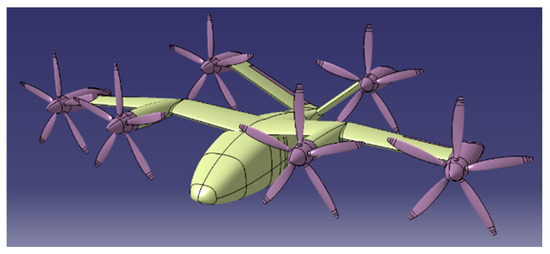
Figure 1.
H3.eVTOL.
This paper discusses and optimizes the concept of the aerodynamic design of H3.eVIOL’s wing using CFD and estimates the range of H3.eVTOL based on the numerical calculation results. The results show that the range of H3.eVTOL meets the design requirements, and the aerodynamic design concept of the wings described in this paper is able to meet the requirements of the project.
2. Development of Research Questions
The requirements for H3.eVTOL performance are as follows: takeoff weight of 3000 kg, cruising altitude of 1000 m, cruising speed of 300 km/h, and maximum range of 300 km.
According to the requirements of H3.eVTOL, the research questions concerning the wing are as follows:
RQ1.
The structural space inside the wings should be as large as possible to accommodate batteries;
Therefore, the thickness of the wing should be as large as possible.
RQ2.
The H3eVTOL should have a long range.
Therefore, the lift-to-drag ratio in the cruising stage should be as large as possible.
3. Methodology
3.1. Airfoil Selection
As the H3.eVTOL belongs to low-speed aircraft, the wing airfoil is selected from the low-speed airfoils. This paper presents a statistical analysis of the lift and drag characteristics of a series of low-speed airfoils, including NACA 5-digit series airfoils, NACA 6-series airfoils [1], natural laminar flow (NLF) airfoils [2,3,4], and high lift airfoils [5,6,7,8]. The lift and drag characteristics are derived from the wind tunnel test data from NASA’s technical report. According to the design requirements of H3.eVTOL, the Reynolds number of H3.eVTOL is about 6 million. Therefore, this paper summarizes the lift and drag characteristics of the airfoil at a Reynolds number of 6 million from NASA’s technical report. Due to the distributed propulsion of the H3.eVTOL, the proportion of the slipstream immersed wing area to the total area of the wing is relatively large, resulting in a turbulent boundary layer on the wing surface. Therefore, the data of fixed transition at the leading edge are chosen as the basis for comparison.
Part of the statistical results of the lift and drag characteristics of NACA 5-digit series airfoils, NACA 6-series airfoils, natural laminar flow series airfoils, and high lift series airfoils are shown in Figure 2, Figure 3, Figure 4 and Figure 5. The statistical results indicate that
- (1)
- Among the 5-digit series NACA airfoils, NACA 23015 has the highest maximum lift-to-drag ratio;
- (2)
- Among the NACA 6-series airfoils, NACA 63.2-615 has the highest maximum lift-to-drag ratio;
- (3)
- Among the natural laminar flow series airfoils, NLF(1)-0416 and NLF(1)-0215F have the highest maximum lift-to-drag ratio;
- (4)
- Among the high lift series airfoils, MS(1)-0313 and GAW-2 have the highest maximum lift-to-drag ratio. However, considering that the thickness ratio of the two airfoils is only 13%, MS(1)-0317 and GAW-1 are used.

Figure 2.
NACA 5−digit series airfoils’ polar curves.
Figure 2.
NACA 5−digit series airfoils’ polar curves.


Figure 3.
NACA 6−series airfoils’ polar curves.
Figure 3.
NACA 6−series airfoils’ polar curves.


Figure 4.
NACA NLF series airfoils’ polar curves.
Figure 4.
NACA NLF series airfoils’ polar curves.


Figure 5.
NACA high lift series airfoils’ polar curves.
Figure 5.
NACA high lift series airfoils’ polar curves.

The lift and drag characteristics of NACA 23015, NACA 63,2-615, NLF (1)-0416, NLF (1)-0215F, MS (1)-0317, and GAW-1 airfoils are shown in Figure 6. As shown in Figure 6, GAW-1, MS(1)-0317, NLF(1)-0416, and NLF(1)-0215F airfoils have the highest maximum lift-to-drag ratio. Therefore, the airfoil of the wings can be further screened from the above four airfoils. The corresponding airfoil shapes are shown in Figure 7, Figure 8, Figure 9 and Figure 10.
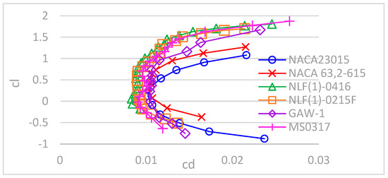
Figure 6.
Comparison of airfoils’ polar curves.
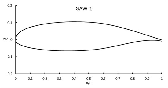
Figure 7.
GAW−1 airfoil.
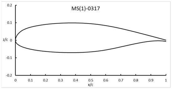
Figure 8.
MS(1)−0317 airfoil.
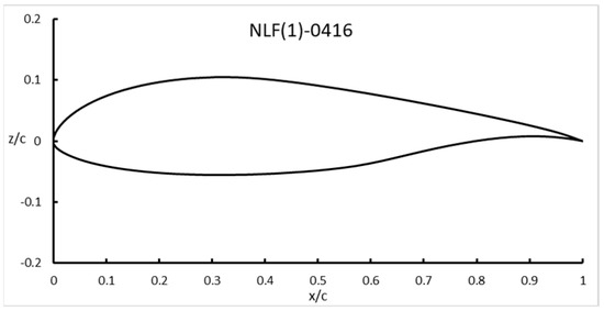
Figure 9.
NLF(1)−0416 airfoil.
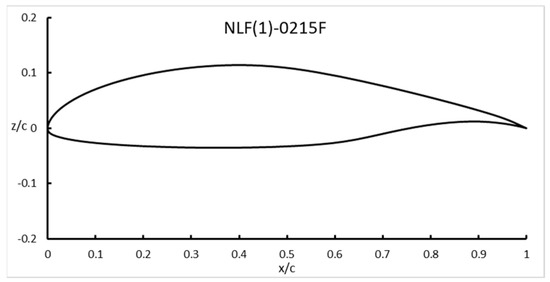
Figure 10.
NLF(1)−0215F airfoil.
3.2. Analysis of the Wings’ Geometric Parameters
The geometric parameters of the wings include area S, the chord of wing root cr, the chord of wing tip ct, wing span b, and the sweep angle of leading edge ΛLE.
- (1)
- Wing area:
This paper analyzes the design of wing area for the cruising stage.
For the wing area S, the following formula is satisfied in the cruising stage:
In the formula, CLcr is the cruising lift coefficient; WTO is the takeoff weight; Vcr is the cruising speed; and ρ is the air density. WTO, ρ, and V are known, while C and S are unknown. To improve the endurance of the aircraft, this paper aimed to obtain the maximum lift-to-drag ratio of the cruising stage. By optimizing the wing incidence angle, the cruising lift coefficient corresponding to the maximum lift-to-drag ratio of the cruising stage will be determined, and then, the wing area will be optimized.
The initial value of the optimized design of the wing area in this paper is determined based on statistical values. The existing data on eVTOL wing loading are shown in Figure 11. Figure 11 indicates that the wing loading of the tiltrotor eVTOL is between 200 kg/m3 and 250 kg/m3. In this paper, the initial wing area is determined to be 13.3 m2 based on 225 kg/m3.
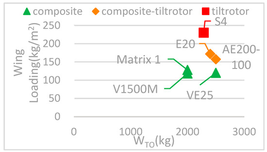
Figure 11.
Wing loading of several eVTOLs.
- (2)
- Wing span:
According to the rotor layout of H3.eVTOL, all of the six tiltrotors are distributed in a hexagonal shape, as shown in Figure 12. The wing span should ensure that the tiltrotor on the wing will not overlap in the longitudinal direction while leaving a portion of the fuselage. The maximum width of the fuselage is about 1.6 m, and the diameter of the tiltrotor is about 3 m; therefore, the span length b is taken as 10.6 m.
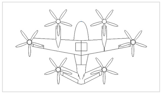
Figure 12.
Tiltrotors’ distribution of H3.eVTOL.
- (3)
- Wing tip and root chord:
H3.eVTOL has two tiltrotors arranged on both of the wing tips, so that the rigidity of the wing tips should be large enough. In order to reduce the structural weight, this paper selects an airfoil with a thickness ratio of no less than 15%. According to the design requirements, the arrangement of the tilt axis requires a wing tip thickness of at least 0.13 m. Therefore, as the thickness ratio of the wing tip airfoil is 15%, it can be preliminarily determined that the wing tip chord ct is about 0.867 m, so that the initial value of cr is approximately 1.649 m.
- (4)
- Wing position:
The center of gravity position of H3.eVTOL has not been determined yet. When determining the longitudinal position of the wing root, the X-coordinate of the leading edge of the wing root is preliminarily designed to be 1.99 m, so that the design of wing body fairing will be simpler in the modeling process. The position of the wing tip is mainly limited by the tip tilt mechanism, and the tip tilt axis is designed to coincide with the midpoint of the camber line of the wing tip profile, as shown in Figure 13.
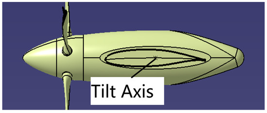
Figure 13.
Tilt Axis Position.
In summary, the preliminary design of the wings is shown in Figure 14, with a forward sweep angle of approximately 3° at the leading edge.
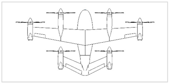
Figure 14.
Preliminary design of the wing.
3.3. Preliminary Design of the Tail
For different airfoils, in addition to the lift and drag characteristics, the moment characteristics are also different; therefore, the trim drag generated by the tail wing should be taken into account. Therefore, a preliminary design for the H3.eVTOL tail should be provided.
The aerodynamic design of the H3.eVTOL tail should consider the installation of the tilt rotor. The H3.eVTOL has a V-tail, and its shape is rectangular, with a 15% thickness ratio symmetrical airfoil. NACA 0015 is primarily selected. The design method for the chord and tip position of the tail is the same as that of the wing tip and will not be repeated.
To increase the distance between the tail and the wing as much as possible, the installation position of the tail root on the fuselage must be as far back as possible. The design result of the tail is shown in Figure 15: the dihedral angle is 37°, and the sweep angle is 20°. The incidence angle of the tail should be optimized, ultimately ensuring that the pitch moment of the H3.eVTOL is 0.
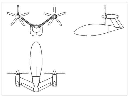
Figure 15.
Preliminary design of the tail.
3.4. Modeling
According to the design in Chapter 1, the wings are designed using NLF(1)-0416, NLF(1)-0215, MS(1)-0317, and GAW-1 airfoils, with incidence angles ranging from 1° to 6°.
The center of gravity (C.G.) is located at the longitudinal midpoint of the fuselage cabin, as shown in Figure 16.
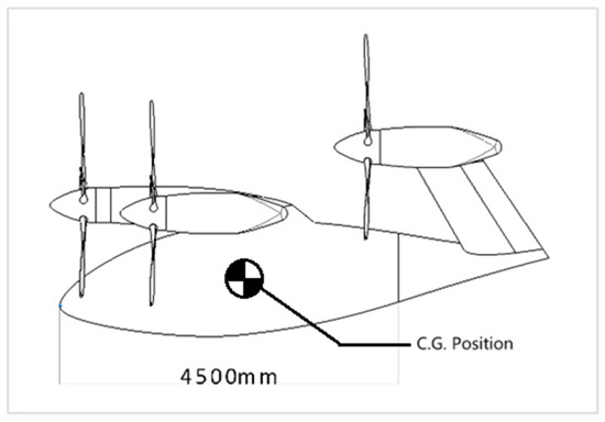
Figure 16.
Center of gravity.
3.5. Mesh
The mesh type is tetrahedral, with a total of 16 million, as shown in Figure 17, and the mesh is refined in the wake region to improve the accuracy of drag prediction.
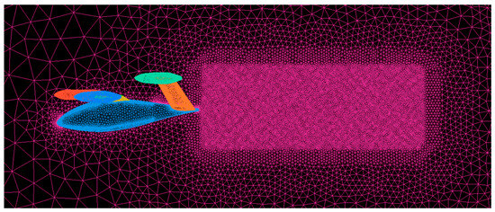
Figure 17.
Fluid domain mesh.
3.6. Settings
Using the CFX in the fluid module of ANSYS 2020 software for steady-state calculation, the specific settings are as follows.
| Fluid | Air |
| Density | 1.1117 kg/m |
| Temperature | 281.65 K |
| Pressure | 89,876 Pa |
| Viscosity | 1.7579 × 10⁻⁵ N∙s/m |
| Velocity | 300 km/h |
| Turbulence Model | Shear Stress Transport (SST) [9] |
| Fuselage Angle of Attack | 0° |
The coordinate frame used for the calculation is shown in Figure 18.
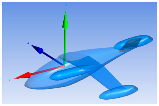
Figure 18.
Coordinate frame.
4. Results and Analysis
4.1. Results
- (1)
- The GAW-1 airfoil scheme has the maximum lift-to-drag ratio of 16.9 among the high lift airfoils;
- (2)
- The NLF(1)-0215F airfoil scheme has the maximum lift-to-drag ratio of 18 among the natural laminar flow airfoils;
- (3)
- The lift-to-drag ratio of the NLF(1)-0215F airfoil scheme reaches its maximum value at a wing incidence angle of 3°–4°, while other schemes reach their maximum value at a wing incidence angle of 5°;
- (4)
- The lift-to-drag ratio decreases significantly after the wing incidence angle of the NLF(1)-0215F scheme exceeds 4°. Therefore, it is recommended that the wing incidence angle of NLF(1)-0215F scheme is 3°.

Figure 19.
Kcr~CLcr curves.
Figure 19.
Kcr~CLcr curves.


Figure 20.
Kcr~φw curves.
Figure 20.
Kcr~φw curves.

In summary, the GAW-1 airfoil has the maximum lift-to-drag ratio among high lift airfoils, while the NLF(1)-0215F airfoil has the maximum cruising lift-to-drag ratio among natural laminar airfoils. The optimal incidence angles for the corresponding schemes are 5°and 3°, respectively.
Regarding the maximum lift coefficient and stall characteristics of H3.eVTOL, the stall type of the GAW-1 airfoil belongs to the trailing edge stall, and the flight test of the Y-12E aircraft using the GAW-1 airfoil also showed that it was easy to recover from the stall. Therefore, the stall characteristics of the GAW-1 airfoil can meet the requirements. However, there is no application for the NF(1)-0215F airfoil among the company products. Considering the deviation of the CFD method in predicting stall, this paper suggests a comparison and verification of the stall characteristics and maximum lift coefficient of the H3.eVTOL for the above two airfoil schemes using the wind tunnel test before making the final decision.
According to the conclusion, based on Formula (1) and the calculation results, the aerodynamic design schemes of the wings are shown in Table 1.

Table 1.
Aerodynamic design schemes of the wings.
4.2. Analysis
This paper only calculates the range during the level flight phase. The range of H3.eVTOL is
Note:
- R range, km
- Kcr lift-to-drag ratio in cruise stage
- ηm motor efficiency
- ηp propeller efficiency
- WE empty weight
- Wcrew crew weight
- Wtfo weight of trapped fuel and oil
- WPL payload
- SE energy density of the battery, W∙h/kg
Currently, the known eVTOLs mostly use permanent magnetic synchronous motors, whose efficiency can exceed 90% over a wide power range; therefore, ηm is taken as 0.9. Regarding the efficiency of the propeller, ηp can be temporarily taken as 0.8.
The existing aircraft statistics indicate that there is a linear relationship between the logarithm of WE and the logarithm of WTO for the same type of aircraft. Different references have different methods for this linear relationship. According to reference [10], WE and WTO comply with the following formula:
Estimating H3.eVTOL as a multi-engine propeller aircraft with a coefficient A of 0.0966 and a coefficient B of 1.0298, WE = 1.76 × 10⁴ N.
According to reference [11], WE and WTO comply with the following formula:
If H3.eVTOL is calculated as a light general aircraft with a coefficient A of 0.911 and a coefficient B of 0.947, then WE = 1.55 × 10⁴ N.
This paper takes the average of the results calculated by the above two methods for the empty weight: WE = 1.66 × 10⁴ N.
According to the design requirements, H3.eVTOL would carry one crew member and four passengers. For the crew, calculated at 175 lb per person and carrying 30 lb of luggage, Wcrew = 205 lb = 92.9 kg; for the passengers, assuming that each person is 200 lb for medium and short distances, WPL = 362.4 kg. The Wtfo of H3.eVTOL is 0.
For SE, referring to the products of CATL, its official website shows that the energy density of mature battery products can reach 255 Wh/kg.
In summary, after calculation, the range of the GAW-1 airfoil scheme is 323.3 km, while the range of the NF(1)-0215F airfoil scheme is 344.4 km, both of which meet the range requirements.
5. Discussion and Conclusions
This paper compares and analyzes two high lift airfoils and two natural laminar flow airfoils as alternative wing schemes based on the wind tunnel test data of various low-speed airfoils according to the design requirements of H3.eVTOL. Under the above alternative schemes, with the goal of obtaining the optimal lift-to-drag ratio of the cruising stage, the incidence angle of the wing was optimized through CFD calculation; the cruising lift coefficient corresponding to the maximum lift-to-drag ratio of the cruising stage was determined; and the geometric design parameters of the wing were optimized. Finally, an optimized wing design scheme based on the GAW-1 and NLF(1)-0215F airfoils was determined. Under the above optimized design scheme, it can be estimated that the range of both schemes exceeds 300 km, meeting the design requirements.
Author Contributions
Conceptualization, Y.Z.; methodology, Y.Z., W.Q. and X.W.; software, Y.Z.; validation, Y.Z.; investigation, Y.Z.; resources, X.W.; data curation, Y.Z.; writing—original draft preparation, Y.Z.; writing—review and editing, Y.Z.; visualization, Y.Z.; supervision, W.Q. All authors have read and agreed to the published version of the manuscript.
Funding
This research received no external funding.
Institutional Review Board Statement
Not applicable.
Informed Consent Statement
Not applicable.
Data Availability Statement
The original contributions presented in this study are included in the article. Further inquiries can be directed to the corresponding author(s).
Acknowledgments
I acknowledge the technical experts who have worked with me for reviewing this paper and further improving its content.
Conflicts of Interest
Author Zheng Yafei, Qiao Wei and Wang Xinlei was employed by the company AVIC Harbin Aircraft Industry Group Co., Ltd.
References
- Abbott, I.H.; Von Doenhoff, A.E.; Stivers, L., Jr. Summary of Airfoil Data. NACA REPORT, No.824. 1945; pp. 70–88. Available online: https://ntrs.nasa.gov/search?title=Summary%20of%20Airfoil%20Data&page=%7B%22from%22:0,%22size%22:25%7D (accessed on 20 July 2024).
- Somers, D.M. Design and Experimental Results for a Natural-Laminar-Flow Airfoil for General Aviation Applications. NASA TECHNICAL PAPER, No.1861. 1981; pp. 68–69. Available online: https://ntrs.nasa.gov/search?title=Design%20and%20Experimental%20Results%20for%20a%20Natural-Laminar-Flow%20Airfoil%20for%20General%20Aviation%20Applications&page=%7B%22from%22:0,%22size%22:25%7D (accessed on 20 July 2024).
- McGhee, R.J.; Viken, J.K.; Pfenninger, W.; Beasley, W.D.; Harvey, W.D. Experimental Results for a Flapped Natural-Laminar-Flow Airfoil with High Lift-Drag Ratio. NASA TECHNICAL MEMORANDUM, No.85788. 1984; pp. 17–48. Available online: https://ntrs.nasa.gov/search?title=Experimental%20Results%20for%20a%20Flapped%20Natural-Laminar-Flow%20Airfoil%20with%20High%20Lift-Drag%20Ratio&page=%7B%22from%22:0,%22size%22:25%7D (accessed on 20 July 2024).
- Somers, D.M. Design and Experimental Results for a Flapped Natural-Laminar-Flow Airfoil for General Aviation Applications. NASA TECHNICAL PAPER, No.1865. 1981; pp. 93–94. Available online: https://ntrs.nasa.gov/search?title=Design%20and%20Experimental%20Results%20for%20a%20Flapped%20Natural-Laminar-Flow%20Airfoil%20for%20General%20Aviation%20Applications&page=%7B%22from%22:0,%22size%22:25%7D (accessed on 20 July 2024).
- McGhee, R.J.; Beasley, W.D.; Somers, D.M. Low-Speed Aerodynamic Characteristics of a 13-Percent-Thick Airfoil Section Designed for General Aviation Applications. NASA TECHNICAL MEMORANDUM, No.X-72697. 1975; pp. 28–29. Available online: https://ntrs.nasa.gov/search?title=Low-Speed%20Aerodynamic%20Characteristics%20of%20a%2013-Percent-Thick%20Airfoil%20Section%20Designed%20for%20General%20Aviation%20Applications&page=%7B%22from%22:0,%22size%22:25%7D (accessed on 20 July 2024).
- McGhee, R.J.; Beasley, W.D. Low-Speed Aerodynamic Characteristics of a 17-Percent-Thick Airfoil Section Designed for General Aviation Applications. NASA TECHNICAL NOTE, No.D-7428. 1973; pp. 44–45. Available online: https://ntrs.nasa.gov/search?title=Low-Speed%20Aerodynamic%20Characteristics%20of%20a%2017-Percent-Thick%20Airfoil%20Section%20Designed%20for%20General%20Aviation%20Applications&page=%7B%22from%22:0,%22size%22:25%7D (accessed on 20 July 2024).
- McGhee, R.J.; Beasley, W.D. Low-Speed Aerodynamic Characteristics of a 13-Percent-Thick Medium-Speed Airfoil Design for General Aviation Applications. NASA TECHNICAL PAPER, No.1498. 1979; pp. 39–40. Available online: https://ntrs.nasa.gov/search?title=Low-Speed%20Aerodynamic%20Characteristics%20of%20a%2013-Percent-Thick%20Medium-Speed%20Airfoil%20Design%20for%20General%20Aviation%20Applica-tions&page=%7B%22from%22:0,%22size%22:25%7D (accessed on 20 July 2024).
- McGhee, R.J.; Beasley, W.D. Low-Speed Aerodynamic Characteristics of a 17-Percent-Thick Medium-Speed Airfoil Design for General Aviation Applications. NASA TECHNICAL PAPER, No.1786. 1980; pp. 39–40. Available online: https://ntrs.nasa.gov/search?title=Low-Speed%20Aerodynamic%20Characteristics%20of%20a%2017-Percent-Thick%20Medium-Speed%20Airfoil%20Design%20for%20General%20Aviation%20Applica-tions&page=%7B%22from%22:0,%22size%22:25%7D (accessed on 20 July 2024).
- Menter, F.R. Two-equation eddy-viscosity turbulence models for engineering applications. AIAA J. 1994, 32, 1598–1605. [Google Scholar] [CrossRef]
- Roskam, J. Airplane Design Part 1: Preliminary Sizing of Airplanes; Roskam Aviation and Engineering Corporation; Design, Analysis and Research Corporation: Lawrence, KS, USA, 1985; pp. 5–7. Available online: https://www.amazon.com/Airplane-Design-Part-Preliminary-Airplanes/dp/188488542X (accessed on 20 July 2024).
- Nicolai, L.M.; Carichner, G.E. Fundamentals of Aircraft and Airship Design: Volume I—Aircraft Design; AIAA Education Series; American Institute of Aeronautics and Astronautics: Reston, VA, USA, 2010; pp. 124–125. Available online: https://arc.aiaa.org/doi/book/10.2514/4.867538 (accessed on 20 July 2024).


Disclaimer/Publisher’s Note: The statements, opinions and data contained in all publications are solely those of the individual author(s) and contributor(s) and not of MDPI and/or the editor(s). MDPI and/or the editor(s) disclaim responsibility for any injury to people or property resulting from any ideas, methods, instructions or products referred to in the content. |
© 2025 by the authors. Licensee MDPI, Basel, Switzerland. This article is an open access article distributed under the terms and conditions of the Creative Commons Attribution (CC BY) license (https://creativecommons.org/licenses/by/4.0/).