1. Introduction
The Jettisoned FDR is a new type of flight recorder, which is usually installed on an aircraft as a redundant recording device and has an automatic throw function. When the aircraft is flying normally, it is the same as a traditional flight recorder, recording the flight data and audio data of each system of the aircraft; when the aircraft has a serious flight accident, it will automatically be separated from the aircraft, decelerate in air and then fall to the ground or the sea, avoiding the harsh environment caused by aircraft crash, makes it more likely to survive a crash; the Jettisoned FDR can also float on water after crashing into the sea, and the internal positioning transmitter will automatically transmits positioning signals to quickly locate the crash location. Therefore, the Jettisoned FDR can improve the survival rate of existing flight recorders and emergency positioning transmitters can also reduce the difficulty of recovery.
2. Development of Research Questions
At present, Jettisoned FDRs have been used on some military aircraft and a small number of civilian aircraft at home and abroad, including F-18 series fighter jets, S-70B helicopters, and Ka-52 Helicopter, Boeing 737 etc. [
1]. There are already relevant airworthiness provisions in the field of civil aircraft (CS 25.1457, CS 25.1459) and technical standards (TSO-C126c) [
2]. The safety of the separation process of Jettisoned FDRs mainly lies in ensuring that the recorder will not hit the fuselage, vertical tail, or horizontal tail after it is dropped by mistake or accident, so as to avoid safety accidents caused by its own drop. Therefore, the key to ensuring the safe disposal of Jettisoned FDRs lies in safety study of its separation process from the aircraft.
In China, Xiaoyu Li [
3] studied the composition structure of Jettisoned FDR systems, and introduced the definition of the separation grade of Jettisoned FDR systems in detail; Yingjie Ma [
4] simulated the separation process of Jettisoned FDRs installed on a certain type of aircraft under different operating conditions that has proved that the separation process is safe, but its popularization on civil aircraft requires an in-depth understanding of the recorder’s movement characteristics during the separation process, which requires further study into the impact of changes in parameters on the movement of Jettisoned FDR during the separation process from the aircraft.
There are two methods for off-board safety simulation of Jettisoned FDRs [
4], each with its own advantages and disadvantages: one is coupling CFD calculation and unsteady simulation of 6-degree-of-freedom motion equations. This method predicts the trajectory more accurately but has higher requirements for computing equipment and a larger number of calculations; the other is to ensure the unsteady effect, and the aerodynamic coefficient is corrected to obtain the recorder aerodynamic coefficient table. The accuracy of this method can meet the requirements of engineering calculation, but the aerodynamic coefficient obtained is not universal.
This article uses the simulation method of computational fluid dynamics overset grid technology coupled with the rigid body’s 6-degree-of-freedom motion equation to separate the Jettisoned FDR installed on a civil aircraft. Unsteady simulation of the process can more accurately simulate the aerodynamic performance and motion trajectory of recorder during separation process, study the impact of various parameters on its movement during separation process, and provide theory basis, technical guidance and data support for its design, installation, flight testing and safe release.
3. Methodology
3.1. Governing Equation
This article uses ANSYS Fluent 2024 R1 [
5], with the discrete method based on pressure and finite volume, and the dual-time method for time advancement.
On the moving grid, the three-dimensional compressible Reynolds-averaged N-S equation in integral form is as follows:
where
In the above formula, ρ, p, E, and H, respectively represent the density, pressure, total energy per unit mass, and total enthalpy per unit mass of the fluid; u, v, and w are the velocity components of the fluid along the X, Y, and Z directions, respectively; is the normal relative velocity between the fluid and the grid; is the viscous stress tensor; is the combined term of viscous stress work and fluid heat conduction.
3.2. Turbulence Model
The turbulence model is the
SST k-ω model proposed by Menter [
6], which combines the advantages of the standard
k-ω and standard k-
models by combining standard
k-ω model and standard k-
are implemented with a hybrid function. The final expression of two equations of the mixed model is shown in Equation (2):
Among them, k and ω represent turbulent kinetic energy and dissipation rate, respectively. is a mixing function through which the standard k-ω model can be used near wall and the k- model can be used in the area far from object.
3.3. Coordinate Transformation
In study of the relationship between the body coordinate system and the volume coordinate system of the recorder, first the origin of two coordinate systems should be collocated and translated, then rotate the body coordinate system around an axis until it coincides with the recorder coordinate system. This article defines the angle of rotation as the attitude angle of recorder [
7], respectively: pitch angle
θ, yaw angle
, and roll angle
.
The conversion relationship is as follows:
3.4. Unstructured Overset Grid Technology
Overset grid allows all given boundaries and unit grid areas to move with rigid body without grid deformation, allowing freer relative movement between objects. Considering that overset grids require high grid quality and computational efficiency, this article uses the unstructured hybrid grids [
8]. Among them, the spatial flow field serves as background grid, which is composed of the structured grid encrypted area and its external non-structured grid area. The structured grid encrypted area serves as the movement area of the recorder, and the non-structured grid area uses a tetrahedral grid. Unit, the outer area that is extruded by unstructured grid on recorder surface and oversets with background grid is used as the moving grid area, and triangular prism grid units are used. Under the premise that the surface of recorder is an unstructured grid, the dynamic grid adopts triangular prism grid units to overset with structural grid units of the background. The information transfer in overset area adopts the
FN-FDM (flexible-node finite difference method) [
9]; the main feature of
FN-FDM is that the point selection of difference calculation template is not limited by grid type, which can overcome the problem of errors introduced by interpolation method and has high efficiency and robustness.
3.5. WPFS Model Separation Numerical Simulation
The
WPFS (Wing/Pylon/Finned-Store) model of the Arnold Engineering Development Center in the United States is one of the standard calculation examples in the field of multi-body separation calculations, the specific parameters of the model can be found in the literature [
10]. This example is used in this article to verify the unstructured overset grid technology suitable for multi-body separation simulation.
Figure 1 is the overset grid for
WPFS model, one set of grid is the background grid including wings/pylons, the other set of grid is the moving grid that wraps the missile.
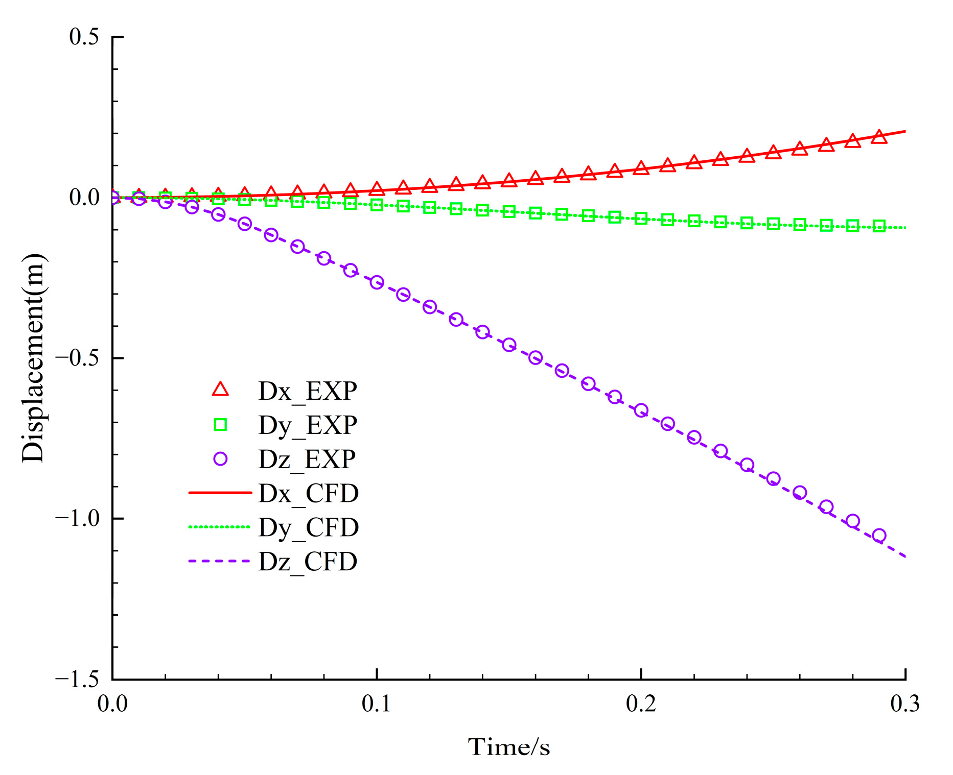
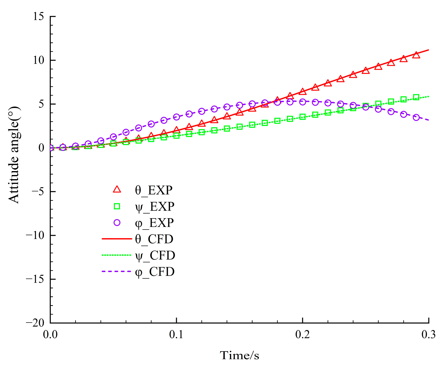
Figure 2 and
Figure 3 are comparison charts between the numerical calculation results and the wind tunnel test results. We can see the change of the missile center’s displacement and attitude angle over time calculated by numerical calculation and wind tunnel test results. The agreement is good, indicating that the non-structured overset grid technology in this article has high accuracy in simulating the machine–bomb separation process.
3.6. Computational Model
The aircraft uses NASA Common Research Model, the airfoil is ONERA OAT15A; the wing area is , the fuselage is approximately cylindrical; the diameter is 6 m; and the total length of the fuselage is 62.76 m; The Jettisoned FDR is installed on the side of the aircraft’s vertical tail and is divided into two layers, inner and outer:
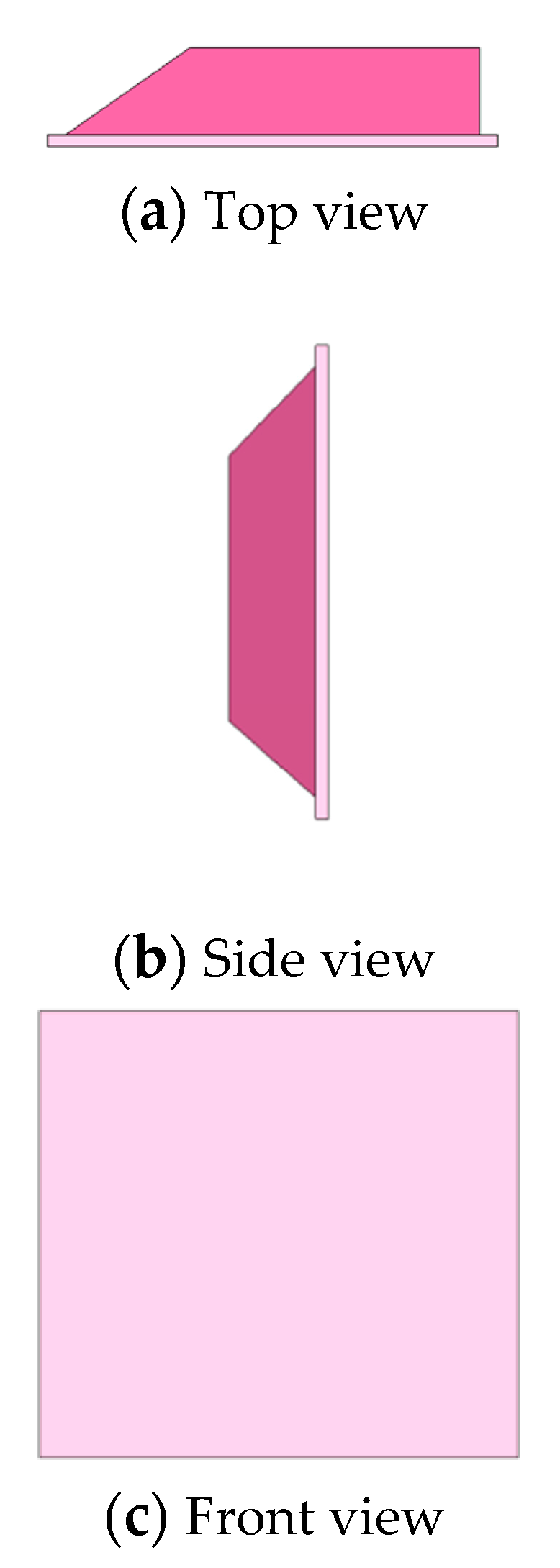
The outer layer is a cube, as the vertical tail surface at the installation site. The inner layer is a 0.2 m high right-angled trapezoidal boss. The slope of inclined side is 45° and the size of the inner rectangular surface is 0.47 m × 0.38 m.
In this paper, based on the characteristics of the low and flat tail of aircraft, the Jettisoned FDR is positioned on the left side of aircraft’s vertical tail along the heading, and the recorder is ejected from the left side by mechanical jettisoning device. The installation position of the Jettisoned FDR is shown in
Figure 4. The 3D model is shown in
Figure 5 which details the dimensions and quality characteristics that are shown in
Table 1.
The following will carry out simulation calculations for the separation process of Jettisoned FDRs installed on an aircraft according to the above method.
3.7. Separation Process of Jettisoned FDR
Assuming the installation position, center position, aerodynamic shape, initial release state, and other parameters of Jettisoned FDRs are determined, after the recorder is ejected from the left side, it gains initial velocity along the heading. The initial angular velocity provided by the release mechanism and the initial velocity in the ejection direction cause it to separate from the aircraft. The separation is influenced by the combined action of airflow and gravity near the vertical tail, forming its release trajectory. In the body coordinate system, since the speed in X is always greater than the speed in the Y direction (ejection direction) and the Z direction (fall), and the installation position’s distance to the trailing edge of vertical tail in the X direction is greater than the distance to the trailing edge of the horizontal tail, the time for aircraft to complete separation from recorder depends on the time required for the recorder to break away from the vertical tail’s edge in the X direction.
3.8. Simulation Operating Conditions Design
The duration of the separation process is short; the mass and the inertia moments of the recorder are small, so the influence of airflow near vertical tail is the dominant factor. The main parameters that affect the airflow near the vertical tail are incoming Mach number, attack angle
, and sideslip angle
. This article focuses on the determined installation site of the recorder on an aircraft and the impact of these three main parameters during the recorder separation process. The cruise state of the aircraft is set as the standard operating condition and the initial release angular velocity
and the initial center throwing speed
. Then, the control variable method was used to design three operating conditions for the three main parameters, and the corresponding parameters of each operating condition were changed three times, respectively. A total of 10 operating conditions including standard operating condition were designed, and the separation process of recorder under these 10 operating conditions was simulated numerically. The influence of change of three main parameters on the trajectory of the Jettison FDR during the separation process is analyzed. The specific parameters of each operating condition are shown in
Table 2:
4. Results and Analysis
4.1. Separation Process of Recorder Under Standard Operating Condition
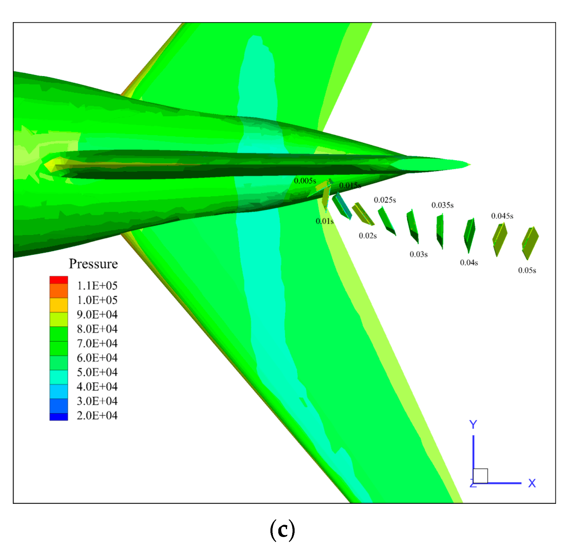
During the separation process, the relative movement of recorder in the Y direction determines whether recorder hits the vertical tail. The relative movement in the Z direction determines whether recorder collides with the horizontal tail. If recorder does not collide with the fuselage, vertical tail or horizontal tail during its separation process, it means that the separation process of recorder is safe. Pressure contours from three views of the separation process of FDR under standard condition are shown in
Figure 6. From
Figure 6 we could see that the recorder’s displacement is mainly distributed in the X direction, its attitude angle in the Y and Z direction have reversed during the process of separation.
4.2. Analysis of the Influence of Incoming Flow Mach Number in Recorder Separation Process
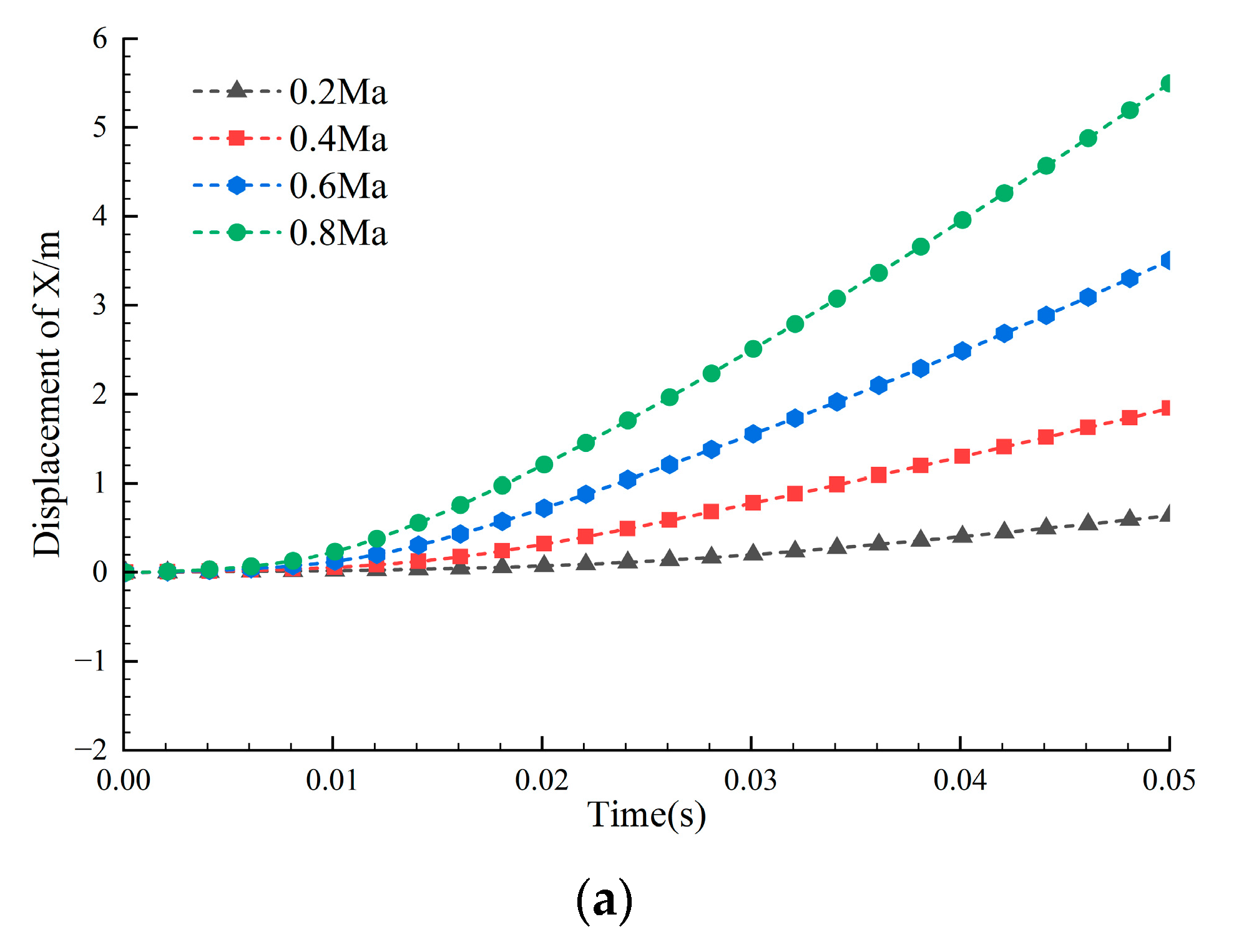
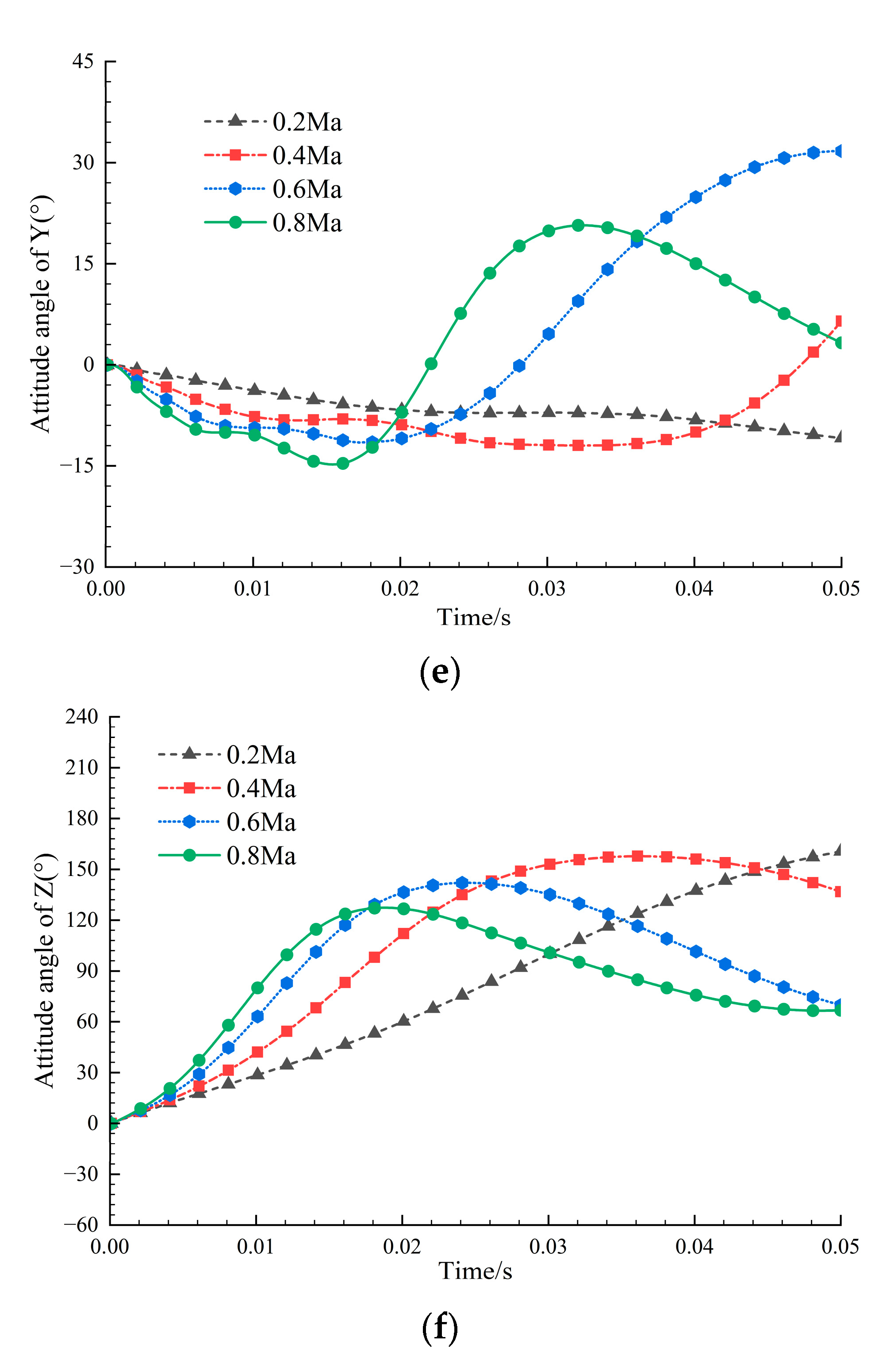
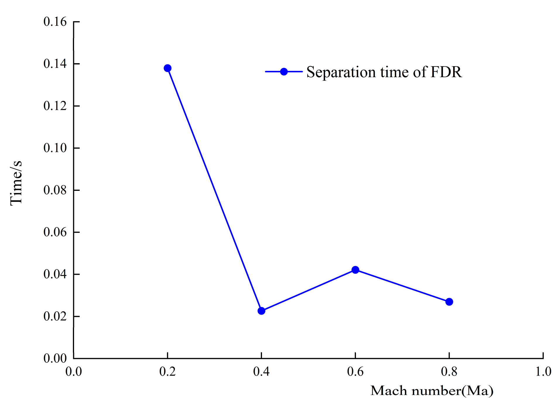
The incoming flow Mach number mainly affects the relative speed of the recorder to the incoming flow in the X direction and the rotational speed in the Z direction during throwing process and has a greater impact on the time to complete separate. By simulating the separation process of the recorder under three operating conditions corresponding to standard operating conditions and the Mach number, the motion of FDR in 6 degrees of freedom during separation process changes with time in body coordinate system as shown in
Figure 7. The separation moments of the recorder are shown in
Figure 8.
It can be seen from
Figure 7 that during separation process, the displacements of recorder’s center in three axes show an increasing trend in specific direction. The displacement of the recorder’s center is mainly distributed in X and Y directions. The displacement in the X direction has the largest change and the separation speed relative to aircraft is also fastest. The displacement of the center in the Y direction is most affected by its own rotation. As the recorder has a flat aerodynamic shape, the displacement in the Z direction is greatly affected by gravity and its own rotation and less affected by aerodynamic forces. Its displacement changes are minimal during the separation time.
During the separation process of the recorder, affected by the incoming flow and the initial throwing angular velocity , the attitude angle in Z direction changes most, and the attitude angles in three directions all began to reverse after reaching the maximum value. After the recorder was separated, the attitude angles in three directions gradually tended to a constant value under the influence of rear airflow.
As the Mach number of incoming flow increases, the displacement of the recorder in the X and Y directions gradually increases at same time during the separation process. Gradually increasing, displacement in the Z direction reverses twice due to the significant change in the attitude angle in the Y direction under the standard operating condition.
As the incoming Mach number increases, at same moment during separation process, the maximum attitude angle of recorder in the Z direction gradually decreases, and the maximum attitude angles in the X and Y directions gradually increase, and the attitude angle fluctuation rhythm on the three axes gradually accelerates, and the stability becomes faster.
Figure 8 shows that when the incoming Mach number is within the range of 0.2–0.8 Ma, the time required for recorder to complete separation shows a trend of fluctuation and attenuation as the Mach number increases. In the figure, the separation time is reduced mostly within 0.2–0.4 Ma, and the recorder separation time is shortest at 0.4 Ma; so the Jettisoned FDR is easiest to separate at around 0.4 Ma.
4.3. Analysis of the Influence of Sideslip Angle in Recorder Separation Process
The sideslip angle
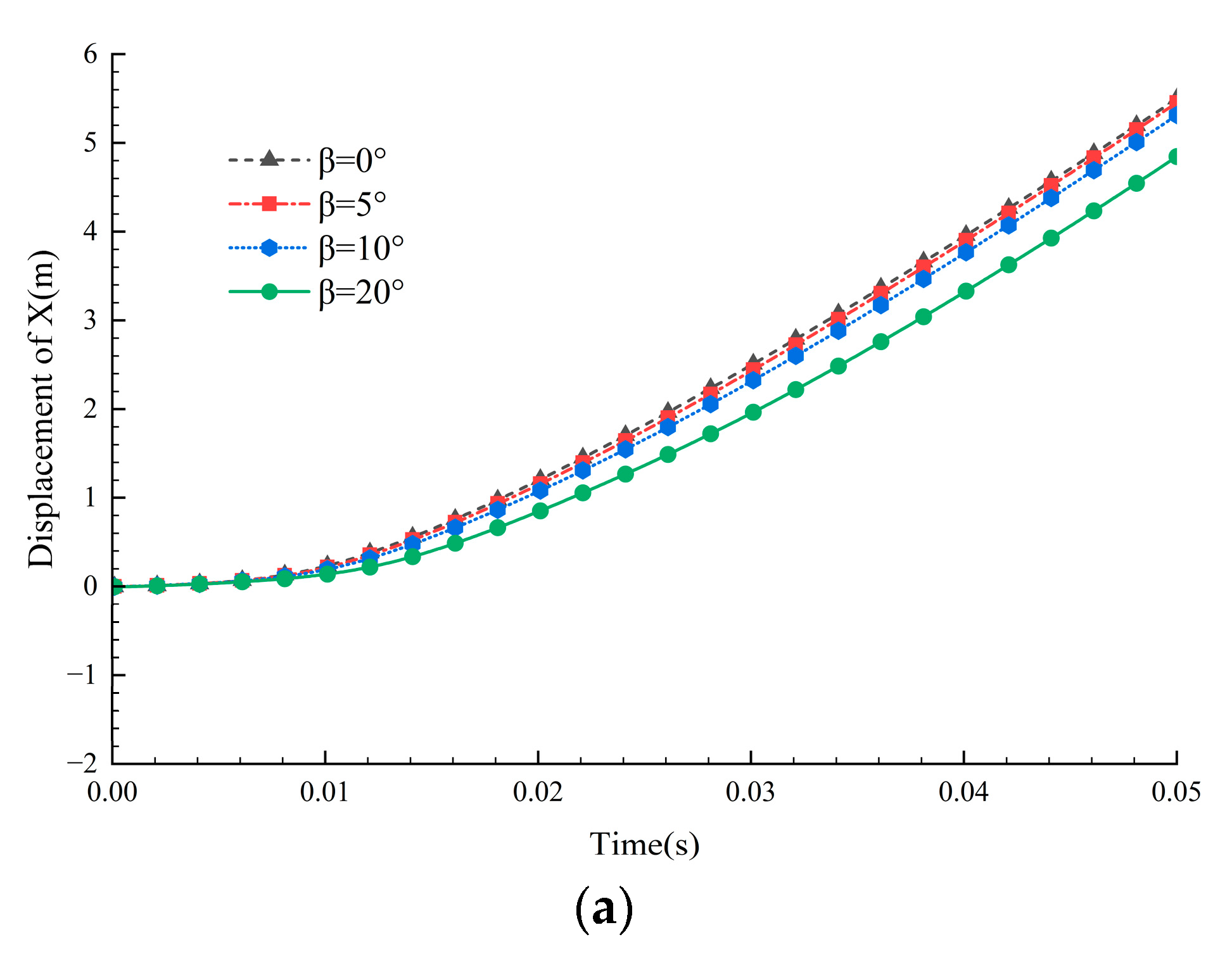
of an aircraft during the separation process determines the components of relative speed between the recorder and the incoming flow in the X and Y directions, and mainly affects the distance between recorder and vertical tail and rotational speed in Y direction. By simulating recorder separation process under three operating conditions corresponding to the standard operating condition and sideslip angle
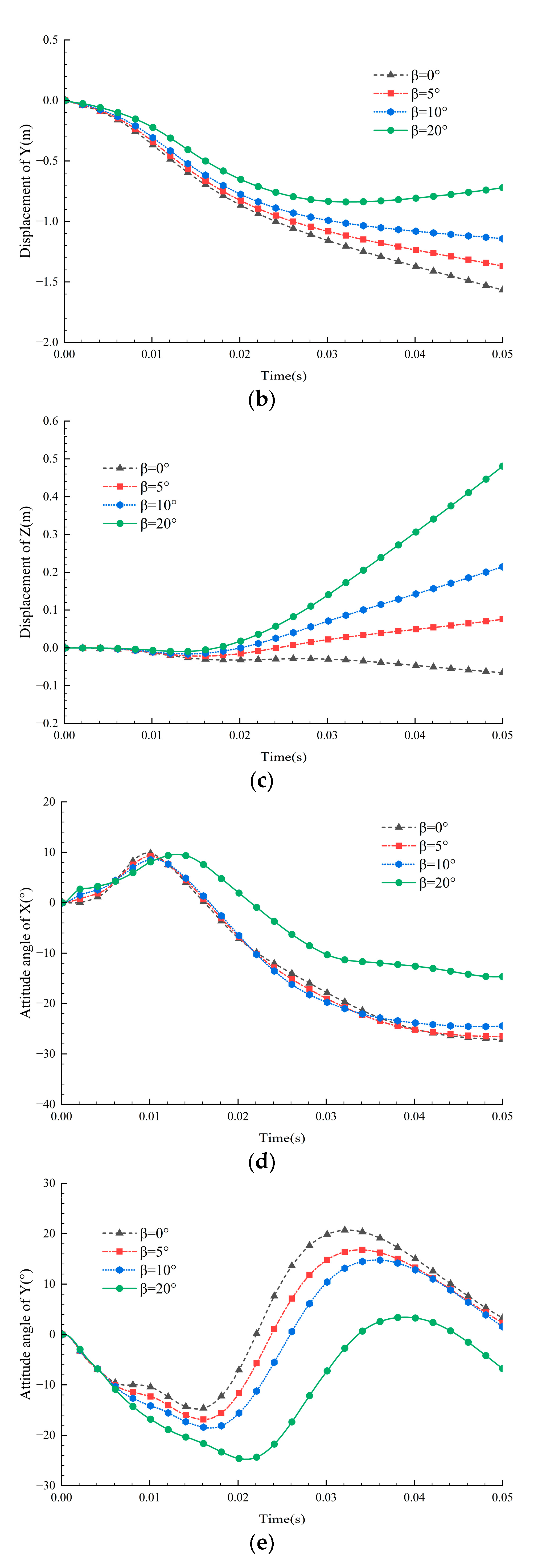
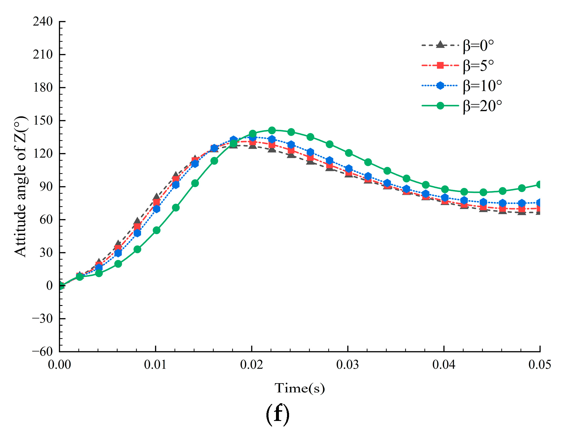
, the recorder’s separation process during separation process was obtained in the body coordinate system. The motion of FDR in 6 degrees of freedom during separation process changes with time in body coordinate system as shown in
Figure 9, and the separation moments of recorder are shown in
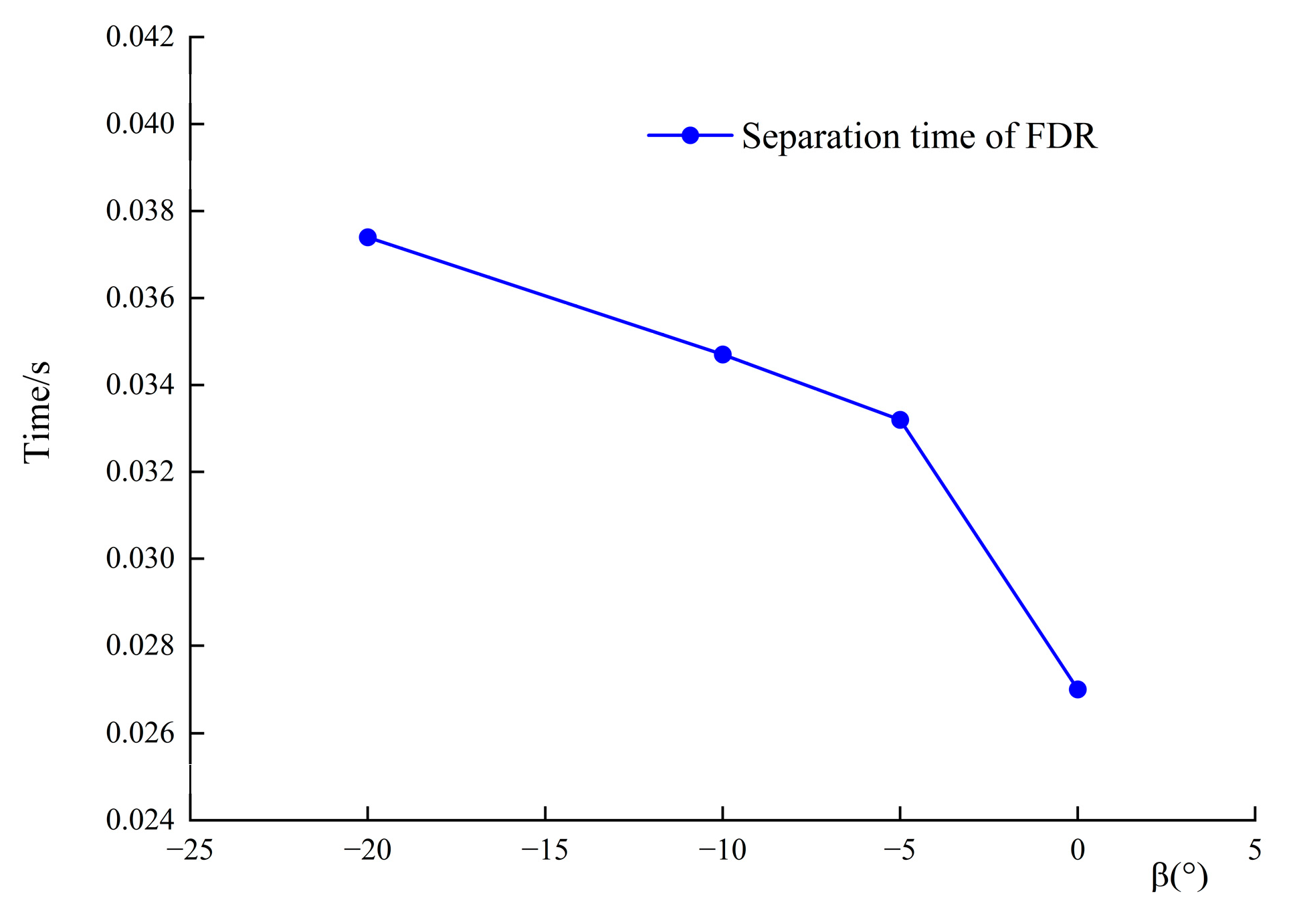
Figure 10.
As can be seen from
Figure 9, during separation process, the displacement of the recorder in the X direction has the largest variation, and the separation speed is also the fastest relative to the aircraft. After the recorder’s center and incoming flow have a relative velocity component pointing to the vertical tail, this component has a direct influence on the displacement and attitude Angle of recorder in the Y direction. The displacement of the center in the Z direction is greatly affected. The displacement in the Z direction of three working conditions with negative sideslip angle is more reversed than that in the standard working condition.
As the sideslip angle
increases, the relative velocity component of the recorder and the incoming flow in the X direction gradually decreases during separation process, so displacement of the center shows the figure characteristics of gradual decrease in
Figure 7a; at the same time, the displacement of the recorder in the Y direction gradually decreases with the increase in the sideslip angle
, and the speed equates faster. In the side slip angle
operating condition, the velocity of center in the Y direction begins to reverse after the recorder rotates 110.6°. Because the attitude angle in the Y direction changes greatly with the increase in the sideslip Angle
β, the displacement of the recorder in the Z direction reverses only once and displacement increases gradually at the same time. The pressure cloud image of the recorder during side-looking separation under this operating condition is shown in
Figure 11.
As the sideslip angle increases, the attitude angle of the recorder changes slightly in the X and Z directions during separate procession, and the attitude angle changes in the Y direction. The amplitude increases significantly, and the overall fluctuation trend of attitude angles on the three axes is relatively consistent, but there is a certain hysteresis effect.
Figure 10 shows that, within sideslip angle range of −20°–0°, the time required for the recorder to complete separation decreases with the increase in the sideslip angle
trend. In this figure, the sideslip angle reduces the recorder separation time most within the range of −5° to 0°, and the recorder separation time reduces less within the range of −20° to −5°. Therefore, the Jettisoned FDR is most easily separated when the sideslip angle is about −5°.
4.4. Analysis of the Influence of Attack Angle in Recorder Separation Process
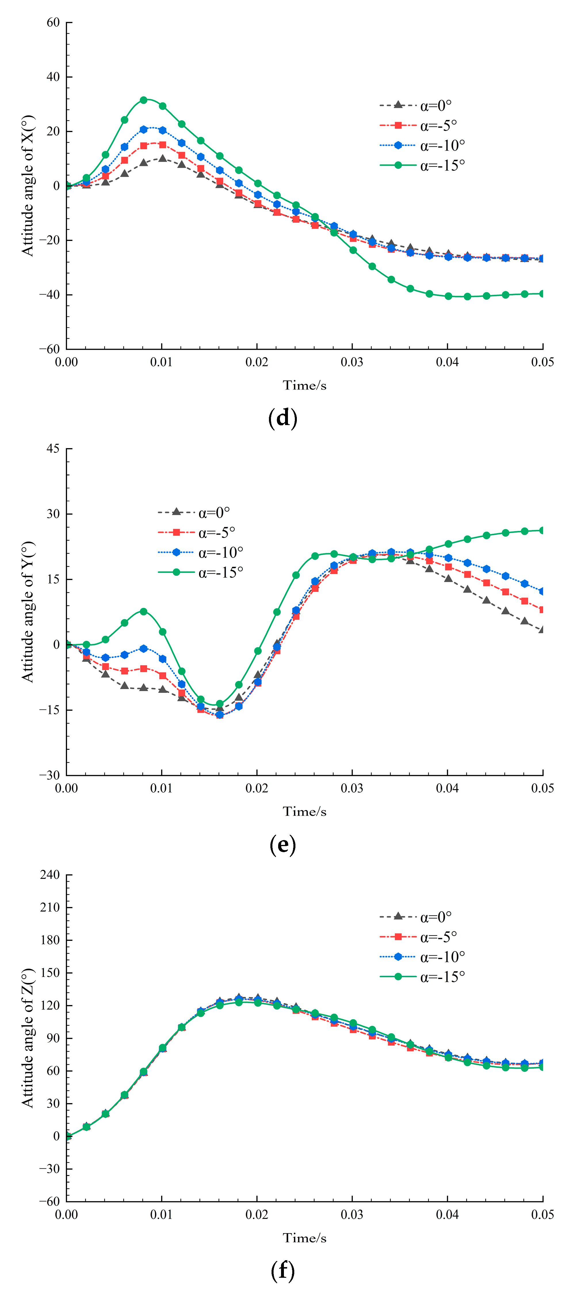
The attack angle
of aircraft during separation process determines the components of relative velocity between recorder and incoming flow in the X and Z directions, and mainly affects the distance between the recorder and horizontal tail. By simulating the recorder separation process under three working conditions corresponding to the standard working condition and a sideslip angle
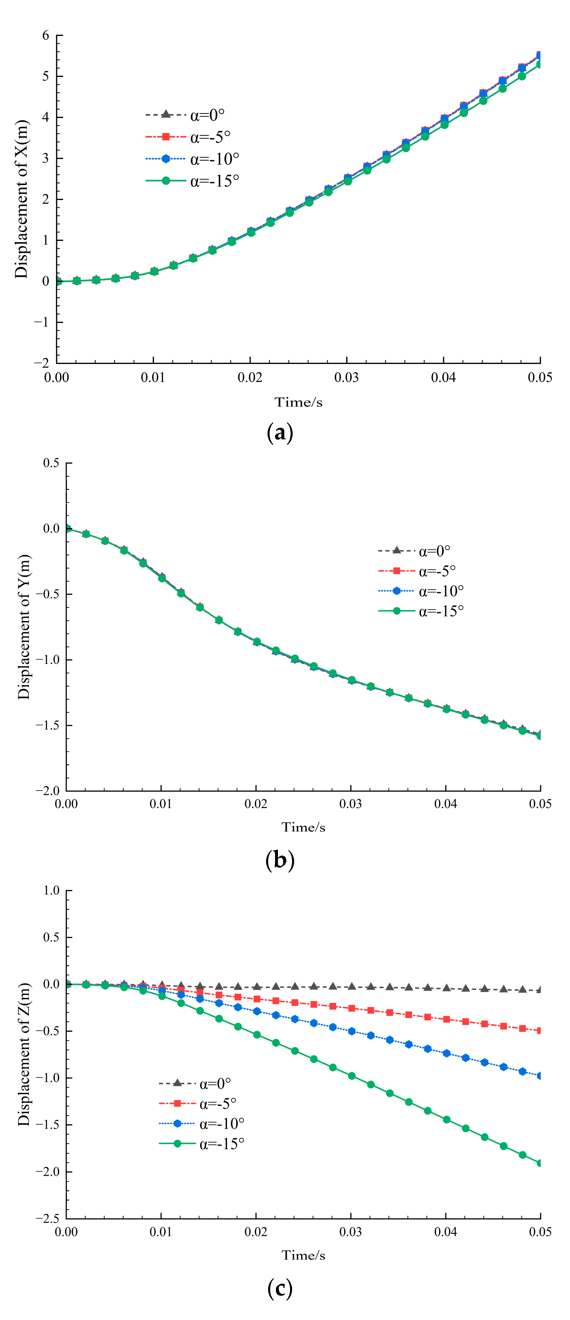
, the recorder separation process was obtained in the body coordinate system. The motion of FDR in 6 degrees of freedom during separation process changes with time in body coordinate system as shown in
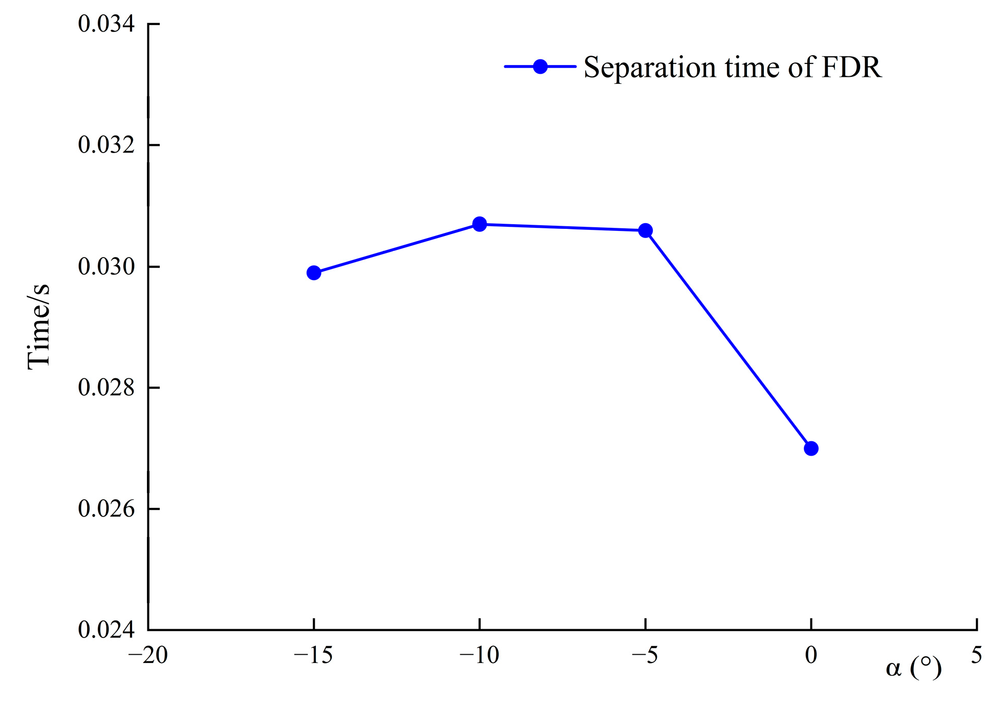
Figure 12, and the separation moments of recorder are shown in
Figure 13.
Figure 11 shows that, during separation process, the displacement of the recorder’s center on three axes show an increasing trend in a specific direction. During the separation process, the displacement and velocity of the recorder still have the largest change under action. It has a great impact on the speed and displacement in the Z direction, and the attitude angles in the X and Y directions.
As the attack angle
increases, the speed and displacement of the recorder in the X and Y directions change less, and the relative speed’s component to incoming flow in the X direction gradually decreases during separation process, so the center displacement shows the characteristics of gradually decreasing as shown in
Figure 7a; at the same time, the displacement of the recorder in the Z direction gradually increases with the attack angle
.
As the attack angle increases, at the same moment during the separation process, the attitude angle of recorder in the X and Y directions gradually increases, and the attitude angle in the Z direction changes slightly, and the overall attitude angle fluctuations on the three axes are relatively synchronous.
Figure 13 shows that within the attack angle range of −15°–0°, the time required for the recorder to complete separation first increases and then decreases with the increase in the attack angle
trend. In this figure, the recorder separation time decreases most within the range of −5°–0° for angle of attack, and slightly increases within the range of −15° to −10°. Therefore, the Jettisoned FDR is most easily separated when the attack angle is about −5°.
5. Discussion and Conclusions
In this paper, the separation process of the Jettisoned FDR installed on a NASA Common Research Model is simulated by the coupling of anisotropic unstructured mixed slip overset grid and rigid body 6-degree-of-freedom motion equation. The numerical simulation ability of simulation method and software for the multi-body separation characteristics is verified. By analyzing simulation results, the following conclusions can be drawn:
The Jettisoned FDR is more likely to collide with the vertical tail during separation process due to the influence of installation position and its own rotation than flat tail. When the sideslip angle of aircraft exceeds −20°, it is necessary to pay attention to the distance between the recorder and the vertical tail after the speed of the center in the Y direction is reversed during the separation time, so as to ensure that recorder does not collide with the vertical tail during the subsequent separation process.
Among the three main aerodynamic parameters affecting the separation process of the Jettisoned FDR, incoming Mach number, attack angle α and sideslip angle β, incoming Mach number have the greatest influence on the time for the recorder to complete the separation process. The recorder separates fastest when the relative velocity of incoming flow is 0.4 Ma and the angle of attack α and the sideslip angle β are about −5°. The sideslip angle β has the greatest influence on the distance between the recorder and the vertical tail. When the sideslip angle β < −20°, it is necessary to pay attention to the reverse movement of recorder’s center in the Y direction to ensure the safety of the separation process. The attack angle α has greatest influence on the distance between the recorder and the flat tail. The flat aerodynamic shape makes the motion of the recorder in the Z direction less affected by the aerodynamic force, so the installation height on vertical tail is more relaxed than the heading position. However, when the recorder has a lower installation position, the separation time is longer, and the negative attack angle is larger; the separation distance between the recorder and the tail is comprehensively considered to ensure the safety of separation process.
The recorder in this paper is usually installed at a higher distance from the flat tail, and the jettisoning process of the Jettisoned FDR with a lower mounting position on vertical tail can be further studied. In addition, the aerodynamic shape of the recorder also has room for further optimization of the design; under the same working conditions, which can make the recorder separation process faster and safer.
Author Contributions
Conceptualization, F.Z. and Z.X.; Methodology, F.Z.; Software, F.Z.; Validation, F.Z. and Z.X.; Formal Analysis, F.Z.; Investigation, Z.X.; Resources, Z.X.; Data Curation, F.Z.; Writing—Original Draft Preparation, F.Z.; Writing—Review & Editing, Z.X.; Visualization, F.Z.; Supervision, Z.X.; Project Administration, Z.X.; Funding Acquisition, F.Z. and Z.X. All authors have read and agreed to the published version of the manuscript.
Funding
This research received no external funding.
Institutional Review Board Statement
Not applicable.
Informed Consent Statement
Not applicable.
Data Availability Statement
Data are contained within the article.
Conflicts of Interest
The authors declare no conflicts of interest.
References
- Ke, Y. Development trend of flight recorder and emergency positioning transmitter. Aviat. Maint. Eng. 2021, 10, 22–25. [Google Scholar]
- Department of Transportation, Aircraft Certification Service Washington, DC. Technical Standard Order, Subject: TSO-C126, 406 MHz EMERGENCY LOCATOR TRANSMITTER (ELT). 23 December 1992. Available online: https://www.sigidwiki.com/images/3/31/C126.pdf (accessed on 1 January 2025).
- Li, X. Research on jettison Flight Recording System. Chinese Society of Aeronautics, Chinese Academy of Aeronautical Studies. In Proceedings of the 7th International Forum on Civil Aircraft Avionics 2018, Shanghai, China, 17–18 April 2018; COMAC Shanghai Aircraft Design and Research Institute: Shanghai, China, 2018; p. 4. [Google Scholar]
- Ma, Y. Simulation study on separation Process of jettison flight Recorder for Civil Aircraft. Aviat. Sci. Technol. 2018, 29, 47–52. [Google Scholar] [CrossRef]
- Zhao, L.; Tian, M.; Li, J.; Wang, M.; Liu, D. Buoy design and take-off Taxiing of electric seaplane. Acta Aeronaut. Sin. 2021, 42, 624590. [Google Scholar]
- Menter, F.R.; Kuntz, M.; Langtry, R. Ten years of industrial experience with the SST turbulence model. Turbul. Heat Mass Transf. 2003, 4, 625–632. [Google Scholar]
- Graster, P.; Ferris, D.H.; Atwell, N.P. Calculation of boundary layer development using the turbulent energy equation. J. Fluid Mech. 1967, 28, 593–616. [Google Scholar]
- Li, H.; Yang, Y.; Zhang, J.; Cui, P.; Jia, H.; Zhang, P. Application of separation vortex simulation method in bomb separation simulation of embedded bomb compartment. Chin. J. Aerodyn. 2022, 40, 190–202. [Google Scholar] [CrossRef]
- Lu, J.; Xu, C.; Chen, J.; Liu, J.; Wang, Y. Research and verification of point selection strategy for flexible-node finite difference method. Acta Aerodyn. Sin. 2024, 42, 65–74. [Google Scholar] [CrossRef]
- Heim, E.R. CFD Wing/Pylon/Finned Store Mutual Interference Wind Tunnel Experiment; Defense Technical Information Center: Fort Belvoir, VA, USA, 1991. [Google Scholar] [CrossRef]
| Disclaimer/Publisher’s Note: The statements, opinions and data contained in all publications are solely those of the individual author(s) and contributor(s) and not of MDPI and/or the editor(s). MDPI and/or the editor(s) disclaim responsibility for any injury to people or property resulting from any ideas, methods, instructions or products referred to in the content. |
© 2025 by the authors. Licensee MDPI, Basel, Switzerland. This article is an open access article distributed under the terms and conditions of the Creative Commons Attribution (CC BY) license (https://creativecommons.org/licenses/by/4.0/).

