Abstract
To optimize welding conditions that ensure the safety and reliability of laser welds, this study established an evaluation method of the fatigue strength for the laser welds of steel sheets over a short period of time. This study focuses on a fatigue limit estimation based on dissipated energy which is caused by micro plastic deformation. As a result, the area at which the temperature changes, due to dissipated energy, is locally high is the fracture origin of the laser welds. The fatigue limit of the laser welds is almost the same as the stress amplitude at which a temperature change occurs due to dissipated energy.
1. Introduction
Laser welding, using a high energy density laser beam, is a quick, high-quality, low-deformation welding technique. Since laser welding is easier to automate and precisely control than other welding techniques, it has been applied in various industrial fields. However, weld defects such as undercuts and blowholes, are prone to becoming the fracture origin for joints. To ensure the safety and reliability of welded joints, it is necessary to clarify the fatigue characteristics of joints and to optimize welding conditions.
This study focuses on the fatigue limit estimation, based on dissipated energy [1]. Materials applied to cyclic loading show a temperature change via the thermoelastic effect. The temperature change, caused by micro plastic deformation, can be measured using infrared thermography and can be used to calculate the energy dissipation. The dissipated energy can then be used to identify the fracture origin of materials and evaluate the fatigue limit in a short time period. Fatigue limit estimation, based on dissipated energy, has been reported for a wide range of materials [1,2]. However, few studies have considered welded structures [3]. This study discusses the feasibility of a fatigue limit estimation for laser welds based on a temperature change due to dissipated energy.
2. Materials
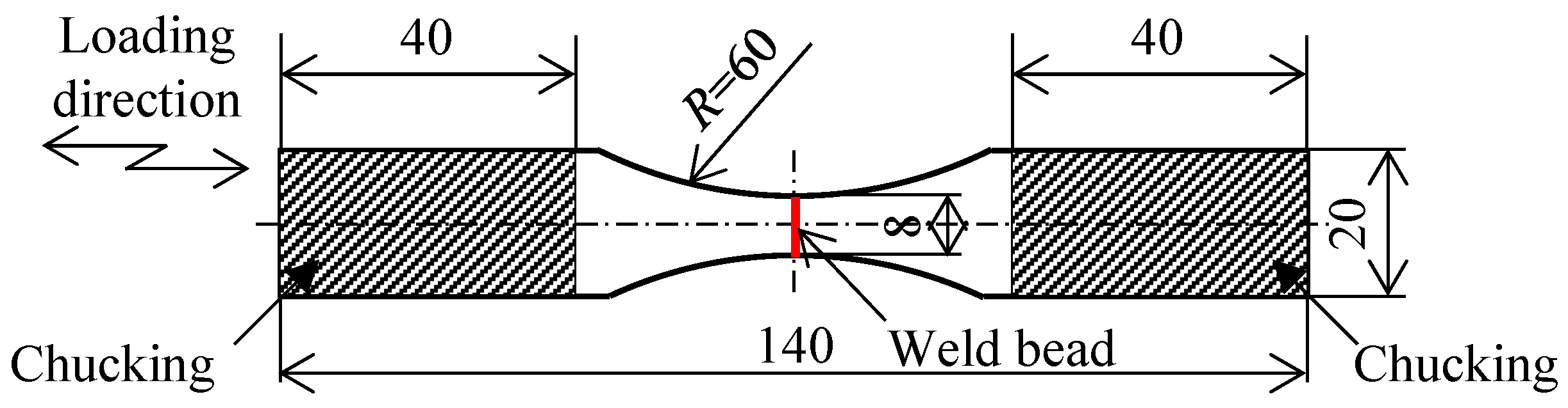
This study used cold-rolled steel sheets (JIS G3141 SPCC) with a thickness of 3 mm. After the material was machined to provide dimensions of 70 mm × 100 mm, the steel sheet surfaces in the longitudinal direction were butted and laser welding was carried out. The laser welding was conducted under the conditions of electric power of 4.0 kW, a welding speed of 1.5 m min−1, defocus length of 5 mm, and an advance angle of 5°. The laser welds were cut into a dumbbell shape with a width of 20 mm perpendicular to the welding direction, as shown in Figure 1. Vickers hardness map was created with an indentation load of 500 mN and an indentation time of 10 s at intervals of 0.3 mm for the welded area and its surrounding area. Fatigue tests were performed with a frequency of 7 to 10 Hz and a stress ratio of −1 and 1 × 10⁷ run-out cycles. The dumbbell-shaped base metal specimen, shown in Figure 1, was prepared separately for the fatigue test. The failure criterion was defined as the point of complete separation of joints.
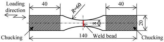
Figure 1.
Shape and dimensions of specimen used in fatigue tests (units: mm).
To measure a temperature change resulting from the dissipated energy for joints, using infra-red thermography, a staircase stress level test was conducted wherein the stress was increased in steps. The test conditions were of a stress ratio of −1 and a loading frequency of 7 Hz. The temperature change of the joints was measured for 3300 cycles for each stress amplitude using infrared thermography. Irreversible heat generation, attributable to plastic deformation, occurs close to the maximum tensile and compressive stresses in one loading cycle. Hence, the frequency component corresponding to twice the loading frequency is defined as a temperature change that occurs due to dissipated energy. Moreover, the phase difference created between thermoelastic temperature change and temperature change caused by the energy dissipation. A high phase difference contains a noise component due to the harmonic components of the testing machine. The temperature change, which is a result of the dissipated energy, was accurately measured by removing the noise component, using the phase lock-in method [4].
3. Results and Discussion
3.1. Cross-Sectional Observation and Hardness Test Results for Laser Welds
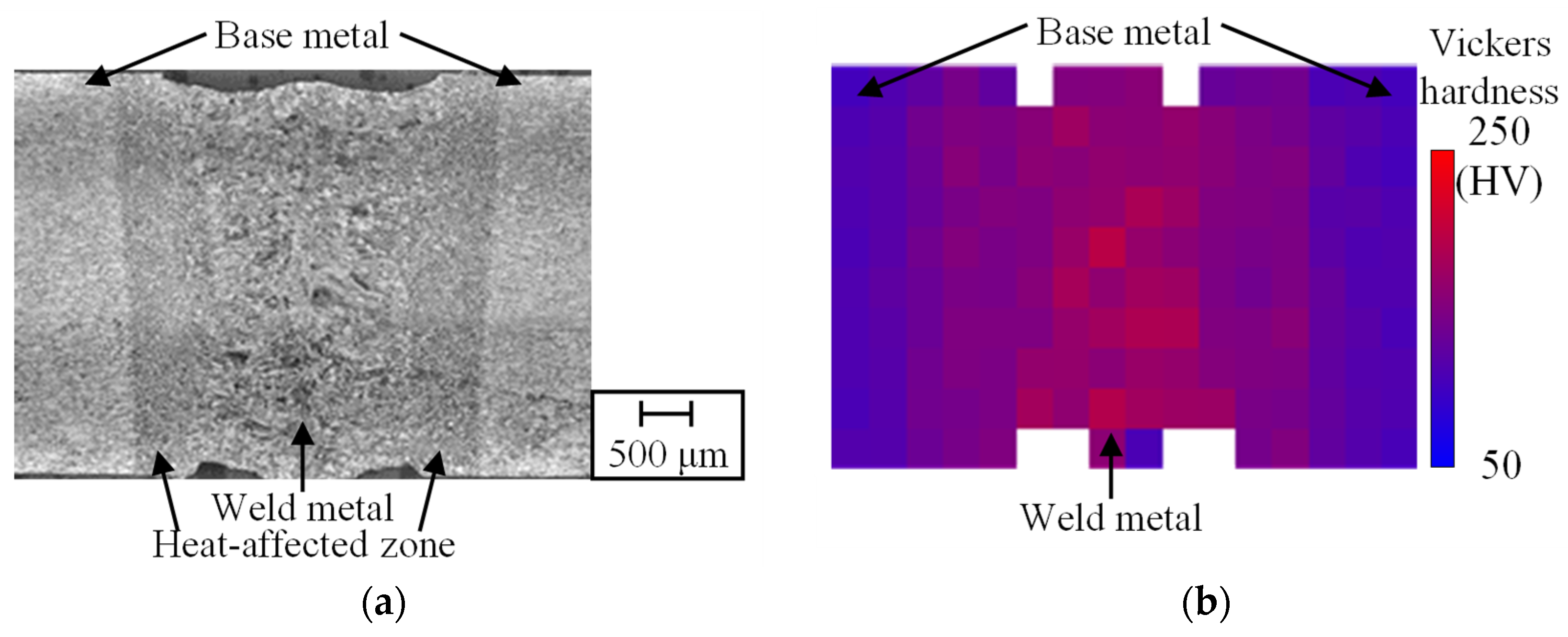
Figure 2a shows an image of the center of the cross section that is perpendicular to the welding direction. The corresponding Vickers hardness map is shown in Figure 2b. These results show three types of microstructures in the laser welds. First, a weld metal with coarsened grains, formed by the rapid melting and solidification of the base metal during welding, appeared in the center of the welded area. Second, a heat-affected zone formed around the weld metal. Lastly, the base metal, which was not affected by the laser welding, appeared around the heat-affected zone. The Vickers hardness of the weld metal is around 1.5 times higher than that of the base metal.
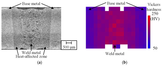
Figure 2.
(a) Microstructure of laser weld cross section and (b) corresponding Vickers hardness distribution.
3.2. Fatigue Test
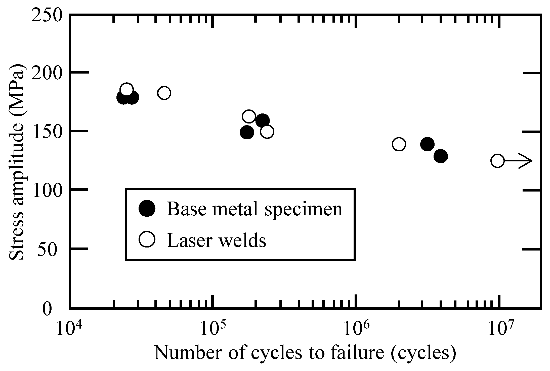
Figure 3 shows the results of the fatigue test, was evaluated in terms of the stress amplitude in the fracture region of the base metal specimens (black marks) and the laser welds (white marks). The fatigue limit for the base metal specimens is from 130 to 140 MPa, and the fatigue limit for the laser welds is the same as that of the base metal specimen.

Figure 3.
Fatigue test results (S-N curves).
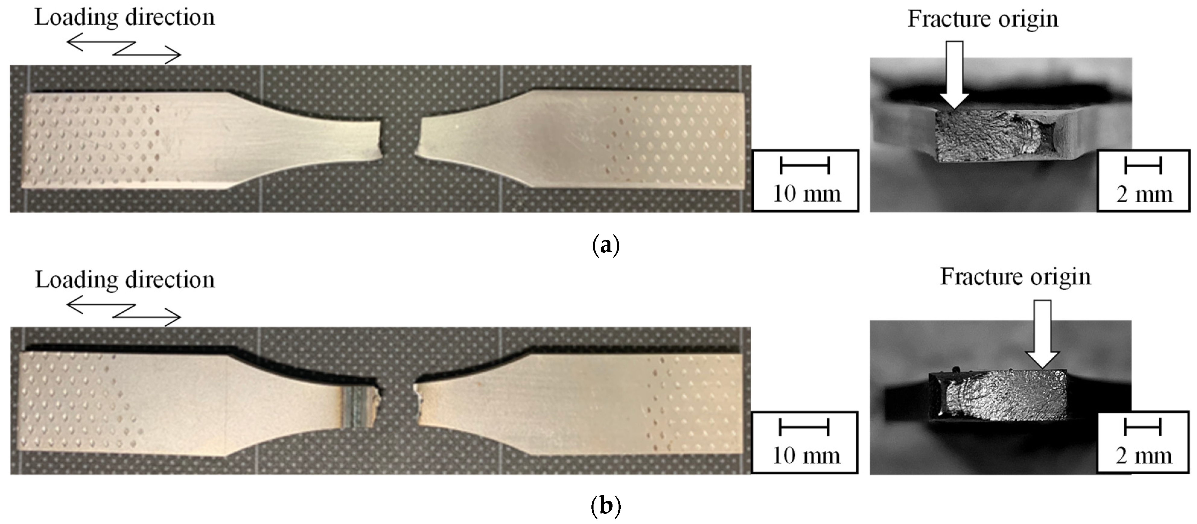
Figure 4 shows the fatigue fracture morphologies for each specimen. The fracture origins of both the base metal specimen and the laser welds are near the specimen surface. The fracture origin of the laser welds is in the area of the base metal at the cross section. This confirms that the Vickers hardness of the welded area is higher than that of the base metal, and that the laser welds used in this study act as successful joints.
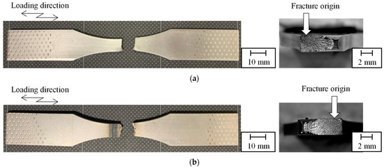
Figure 4.
Fatigue fracture morphology and fracture surface of (a) base metal specimen and (b) laser welds.
3.3. Fatigue Limit Estimation Based on Dissipated Energy for Base Metal and Laser Welds
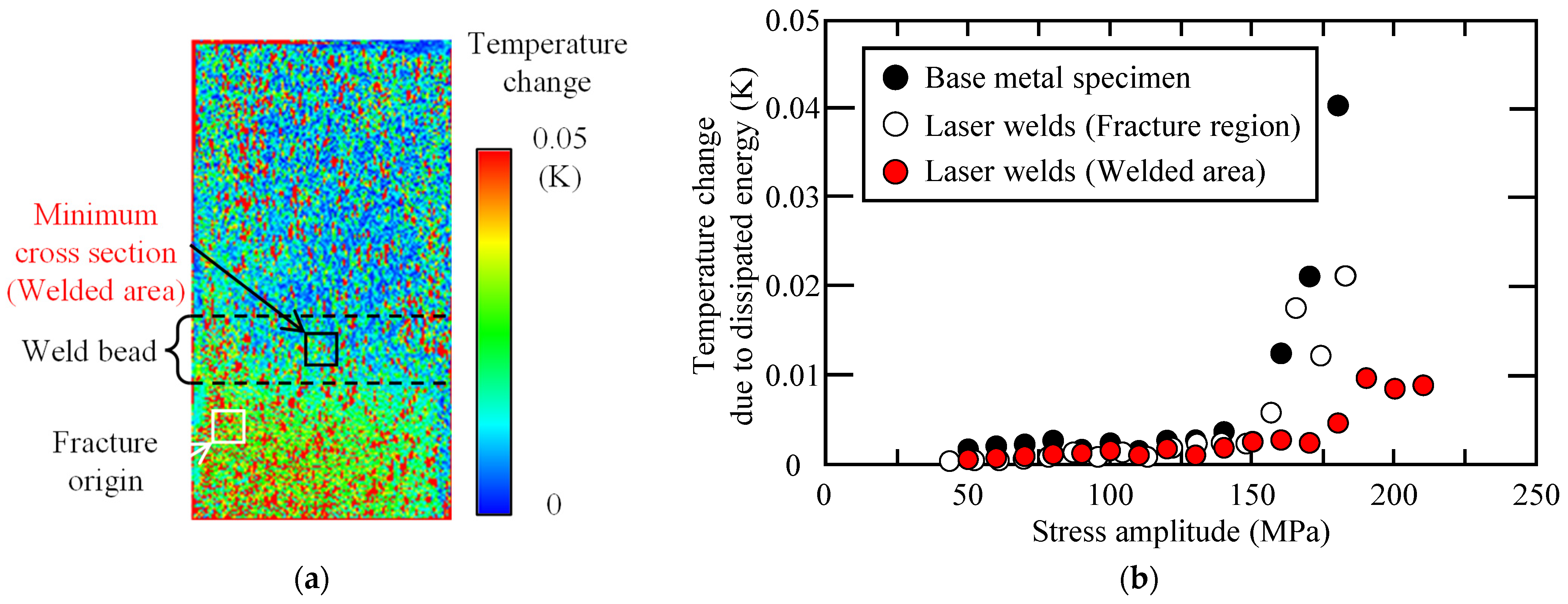
The temperature change that occurred due to dissipated energy for the base metal specimen and laser welds, was measured using a staircase stress level test. Figure 5a shows the temperature change that occurs due to a dissipated energy distribution for the laser welds. The area in which the temperature change occurs as a result of dissipated energy is locally high is the initiation point of a fatigue crack in the joints. The measurement results for the temperature change due to dissipated energy are shown in Figure 5b. The evaluation area of the temperature change, due to dissipated energy, was 10 × 10 pixels at the center of the minimum cross section for the base metal specimen. For the laser welds, the evaluation area was 10 × 10 pixels in the fracture region. The temperature change, that occurs due to dissipated energy, of the base metal specimens (black marks) and the dissipated energy observed in the fracture region of the laser welds (white marks) increases from 140 to 150 MPa. Therefore, the stress amplitude at which the temperature change occurs due to dissipated energy approximately coincides with the fatigue limit of the base metal and laser welds. Thus, the fracture origin and fatigue limit for laser welds for steel sheets can be evaluated using dissipated energy. Moreover, a temperature change, due to dissipated energy, at the minimum cross-section shows red marks in Figure 5b. The stress amplitude at which the temperature changes due to dissipated energy rapidly increases is 170 to 180 MPa at the minimum cross section. This suggests that the fatigue properties of the welded area are superior to those of the base metal.

Figure 5.
(a) Distribution of temperature change due to dissipated energy for laser welds and (b) measurement results for temperature change due to dissipated energy for each specimen.
4. Conclusions
The feasibility of a fatigue limit estimation, based on a dissipated energy measurement for laser welds on steel sheets, was experimentally investigated. The fatigue limit for a base metal specimen and the laser welds in fatigue tests was around 130 to 140 MPa, respectively. The fatigue limit of the laser welds in a fracture region was similar to that of the base metal specimen. It was confirmed that the crack initiation point of the joints was in the base metal region. These fatigue test results are mostly consistent with the stress amplitude at which the temperature changes due to dissipated energy increases. The area with the highest temperature changes, due to dissipated energy, is the crack initiation point in the joints.
Data Availability Statement
The datasets that support the findings during the current study available from the corresponding author upon reasonable request.
Acknowledgments
Vickers hardness test was performed by a testing machine at laboratory of strength & fracture of mechanical materials in Hiroshima university. The authors would like to thank for all of their support. Moreover, this work was supported by JSPS KAKENHI Grant Number JP 21K14043.
References
- La Rosa, G.; Risitano, A. Thermographic Methodology for Rapid Determination of the Fatigue Limit of Materials and Mechanical Components. Int. J. Fatigue 2000, 22, 65–73. [Google Scholar] [CrossRef]
- Akai, A.; Shiozawa, D.; Yamada, T.; Sakagami, T. Dissipation Measurement in Improved Spatial Resolution Under Fatigue Loading. Exp. Mech. 2020, 60, 181–189. [Google Scholar] [CrossRef] [Green Version]
- Shiozawa, D.; Ogino, Y.; Washio, T.; Sakagami, T.; Ueda, H.; Maikino, T. Fatigue Limit Estimation for Single Bead-On-Plate Weld Based on Dissipated Energy Measurement. In Residual Stress, Thermomechanics & Infrared Imaging, Hybrid Techniques and Inverse Problems; Springer: Cham, Switzerland, 2019; Volume 7, pp. 119–123. [Google Scholar]
- Shiozawa, D.; Inagawa, T.; Washio, T.; Sakagami, T. Accuracy improvement in dissipated energy measurement by using phase information. Meas. Sci. Technol. 2017, 28, 044004. [Google Scholar] [CrossRef]
Publisher’s Note: MDPI stays neutral with regard to jurisdictional claims in published maps and institutional affiliations. |
© 2021 by the authors. Licensee MDPI, Basel, Switzerland. This article is an open access article distributed under the terms and conditions of the Creative Commons Attribution (CC BY) license (https://creativecommons.org/licenses/by/4.0/).