Abstract
Joint actuators are the key components in the innovation and iterative optimization of the robots, with a significant impact on both the performances of robots and manufacturing costs. Conventional industrial collaborative robots often use high-precision position and torque sensors, which are not cost-effective or energy-efficient in specific applications like assistive exoskeletons, legged robots, or wheeled robots. Alternatively, we propose a triboelectric-assisted sensory actuator that balances lightweight design, performance, and affordability for large-scale applications. The actuator is composed of a high-power density motor, a low reduction gearbox, and integrated with a rotational triboelectric sensor, which leads to high dynamic performances and low power consumption. The feasibility of the prototype is initially verified by characterizing the angular positioning accuracy and the back drivability. Experiments indicate that the rotational triboelectric sensor is able to accurately detect the angular displacement of the actuator with the self-generated signals. Overall, a highly integrated actuator module with the actuation and sensing circuit is fabricated as a compact design ready for assembling a complete intelligent robot. This actuator holds great potential as a cost-effective, energy-efficient, and versatile solution for modern robotics, crucial for advancing this field and improving human convenience.
1. Introduction
Nowadays, robots are becoming indispensable technologies for future intelligent living and human society. Actuators, as the core components enabling robot motion, are joint modules composed of motors, reducers, encoders, control boards, and control software. By providing electrical, pneumatic, or hydraulic input to the actuators, they generate force, torque, or displacement to control the robot and complete the intended actions [1]. The performance level of actuators primarily depends on their power density, responsiveness, energy efficiency, and impact resistance [2]. In 1983, the WL-10R robot developed by Waseda University used traditional stiffness actuators (TSAs) to achieve bipedal walking; since then, TSAs have been widely used [3,4]. However, TSAs have high motion inertia and cannot address the strength issues of components when robots are subjected to external impacts. Pratt et al. from MIT [5] proposed the concept of series elastic actuators (SEAs) by incorporating elastic elements into rigid TSAs to achieve impact protection, thus solving the problem of component strength under external impacts. However, using SEA usually necessitates sacrificing performance in control bandwidth, system complexity, system mass, and size, leading to limited practical benefits for wearable robots [6]. Currently, quasi-direct drive (QDD) actuators, composed of high torque density motors and low gear ratio transmissions, have gained widespread attention due to their low reflected inertia, resulting in high responsiveness and the ability to drive in reverse. QDD actuators are also considered a promising solution for wearable robot actuators [6,7,8].
In robotic actuators, precise position sensing is crucial for providing the robot controller with the necessary information to achieve accurate motion control. To measure the rotational angle or speed of robotic joints, traditional solutions use optical or magnetic sensors. Optical sensors measure the absolute angular position of a rotating object by detecting the current position of an encoder disk using an optical emitter–receiver [9]. They are not affected by magnetic fields and offer high resolution, but their structures are complex, mechanically fragile, and susceptible to contamination from oil, dust, or dirt. Hall-effect-based magnetic angle sensors are widely used due to their relatively simple structure, low maintenance cost, high reliability, fast working speed, and wide temperature adaptability [10,11,12]. However, the accuracy and linearity of magnetoresistive angle sensors can significantly decrease when the magnetic field is too strong.
In addition to optical and magnetic sensors for angle detection, some novel angle sensors are being researched. Meng et al. [13] proposed a new type of circular position-sensitive detector (CPSD) for continuous detection areas, which avoids the detection blind spots of traditional optical and magnetic encoders and achieves 360° full-range angle detection through a multi-electrode structure. Nakamoto et al. [14] developed a flexible and stretchable anisotropic strain sensor composed of elastomer films and carbon nanotube electrodes, which effectively measures joint angles by reducing the effect of strain in non-target directions to less than 10%, demonstrating its practicality in accurately estimating wrist joint angles with a root-mean-square error of less than 3°.
However, many of the aforementioned methods often face challenges in cost-effectiveness, energy consumption, and material and process compatibility. Based on this, flexible self-powered sensing methods such as triboelectricity [15,16,17], piezoelectricity [18,19], and thermoelectricity [20,21] are gradually being applied. These types of sensing methods can generate electrical signals without external electrical bias, meaning the sensors themselves have zero power consumption and are manufactured using low-cost manufacturing techniques.
Triboelectric nanogenerators (TENGs) refer to devices or mechanisms that generate charges using the coupling effect of triboelectrification and electrostatic induction. Recently, some works have demonstrated the advancement of triboelectricity in measuring parameters such as the angle of rotating objects [22,23].
Building on these advancements, triboelectric-based sensing technology has shown great potential for use in joint actuators as an angle sensor. While the use of TENGs may reduce measurement accuracy, it should be emphasized that millimeter-level operational errors in household environments are unlikely to substantially compromise operational performance [24]. Therefore, triboelectric sensing technology offers new possibilities for developing low-power, low-precision, general-purpose exoskeletons and robotic joint actuators.
In this paper, we propose a novel cost-effective triboelectricity-based actuator, integrating a custom-designed actuator (Figure 1d) with a TENG sensor for position and speed detection (Figure 1c). Figure 1 illustrates our minimalist design strategy to significantly reduce the complexity of the sensing system and the required computational power. The actuator primarily consists of a casing, control board, outer rotor, inner stator, sun gear, and planet gears. The control board controls the rotation of the outer rotor, which is connected to the sun gear via keys, driving the sun gear to mesh with the planet gears. After a single stage of reduction, the output is achieved. The TENG sensor consists of three main components (Figure 1c): a rotor with a grating pattern formed by Kapton tape covering the silver electrode, a bistable micro-slider responsible for detecting clockwise and counterclockwise directions, and a nickel foil that eliminates the effect of electromagnetic induction during motor rotation. In general, the proposed cost-effective triboelectricity-based actuator provides a low-cost, energy-efficient, and highly customizable actuator solution for achieving general-purpose robots with low precision requirements.
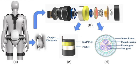
Figure 1.
Triboelectric-assisted sensory exoskeleton system: (a) Schematic diagram of an exoskeleton collaboration system designed to assist human movement. (b) Schematic diagram of a triboelectric-assisted sensory actuator structure. (c) Schematic diagram of a triboelectric sensor architecture. (d) Structural diagram of the actuator section.
2. Materials and Methods
2.1. Designs of Rotational TENG Sensor
Experiments have demonstrated that TENG sensors can be fabricated using methods such as screen printing and MEMS technology [23,25]. In this case, a silver paste grating pattern is formed on the PET layer using screen printing technology. By adjusting the density of the grating array, triboelectric sensors with different precision can be obtained, suitable for various application scenarios. A layer of Kapton film is then applied over the silver paste layer to form a rotor. As shown in Figure 1c, the housing of the TENG sensor, along with a bistable micro-slider fixed in the housing groove, together constitute the stator triboelectric layer. The micro-slider has a protruding semi-cylindrical copper electrode in the middle, which contacts the rotor and generates a current signal using the triboelectric sensing principle. To allow the TENG sensor to detect bidirectional rotational angles using the output signal, a gap is designed at the junction between the housing groove and the micro-slider, allowing the bistable micro-slider to contact electrode E1 or E2, as shown in Figure 2. Specifically, during the rotation of the rotor, the slider displaces within the gap due to friction, causing the conductive nickel foil component at the edge of the slider to contact the corresponding electrode on the housing in a clockwise or counterclockwise direction, thus achieving the detection of bidirectional rotational angles. To prevent the actuator from affecting the performance of the triboelectric sensor during operation, a layer of nickel foil is added to the housing, and a grounding wire is connected to shield the electric field, thereby improving the precision and stability of the output signal [26].
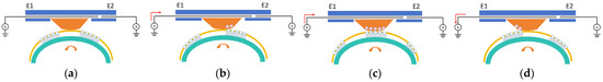
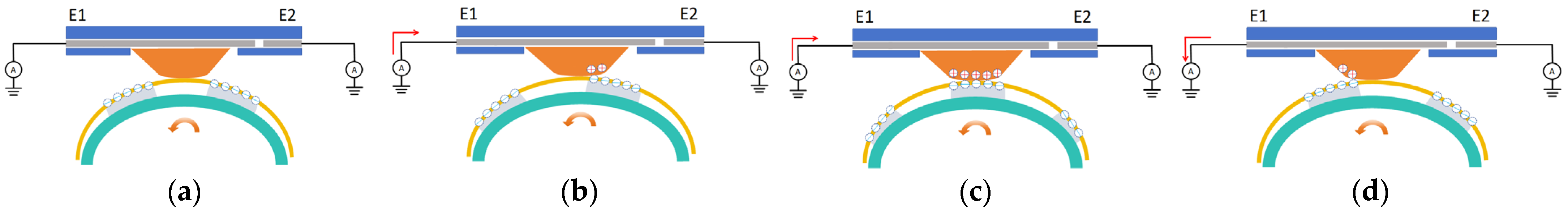
Figure 2.
Working principle of TENG sensor: (a) The slider initially starts moving and makes contact with electrode E1. (b) The slider begins to make contact with the silver grating covered by a Kapton film, causing charge flow. (c) The slider moves to the center of the silver grating, reaching charge equilibrium. (d) The slider gradually separates from the silver grating covered by the Kapton film, causing charge to flow in the opposite direction.
2.2. Working Principle and Sensing Mechanism
As shown in Figure 2a, the slider contacts the Kapton film, generating induced charges. Since the contact area between the two does not change during motor rotation, no charge flow occurs. When the motor rotates to the position shown in Figure 2b, the slider begins to contact the silver grating covered by the Kapton film. The difference in electronegativity between the silver grating and the slider changes the charge density on the electrode, causing charge flow. When the slider moves to the center of the silver grating, as shown in Figure 2c, the contact area remains unchanged, reaching charge equilibrium. As the slider continues to move, as shown in Figure 2d, the slider gradually separates from the silver grating covered by the Kapton film, changing the charge density again and causing a reverse charge flow. From the above friction process, it can be seen that the entire grating array pattern can repeatedly induce output waveform voltage values during rotation, thereby monitoring the rotation state.
2.3. Signal Processing for Real-Time Manipulation
Usually, triboelectric sensors encounter signal fluctuations caused by circuit connections and motion states when applied to smart robots and exoskeletons. The waveforms generated by rotation are mostly continuously varying. However, using digital signals for subsequent processing and analysis is more intuitive. Therefore, it is necessary to accurately convert the original waveform signals into digital signals through a specific method. Variations in peak voltage collected by the sensor pose difficulties for signal recognition based on peaks. Therefore, we developed an external circuit consisting of a voltage regulator circuit and operational amplifier based on Arduino, as shown in Figure 3.
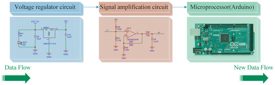
Figure 3.
Flow chart of triboelectric signal processing. “Data Flow” represents raw electrical signals collected from sensors, while “New Data Flow” indicates processed signals after amplification through our conditioning circuit.
In actual signal processing, we provide stable voltage to the operational amplifier circuit through the voltage regulator circuit, while connecting the original friction wave to the input terminal of the operational amplifier, and the output signal is connected to Arduino for processing. By setting parameters in Arduino, the threshold voltage for signal recognition can be determined. To identify all valid signals as much as possible, the threshold voltage should be set low enough, but still higher than the noise to ensure the correctness of motion recognition. When the voltage of the original friction wave exceeds the threshold voltage, the output of Arduino will quickly change to a high level. When the voltage of the original friction wave is lower than the threshold voltage, the output of Arduino will quickly change to a low level. This abrupt change in output voltage forms the edges of square waves. With this method, friction force sensor signals can be easily identified and applied in micro-processors. Specifically, we can measure the rotational angle at the actuator output by counting the number of square wave signals and considering the spacing of the grating pattern.
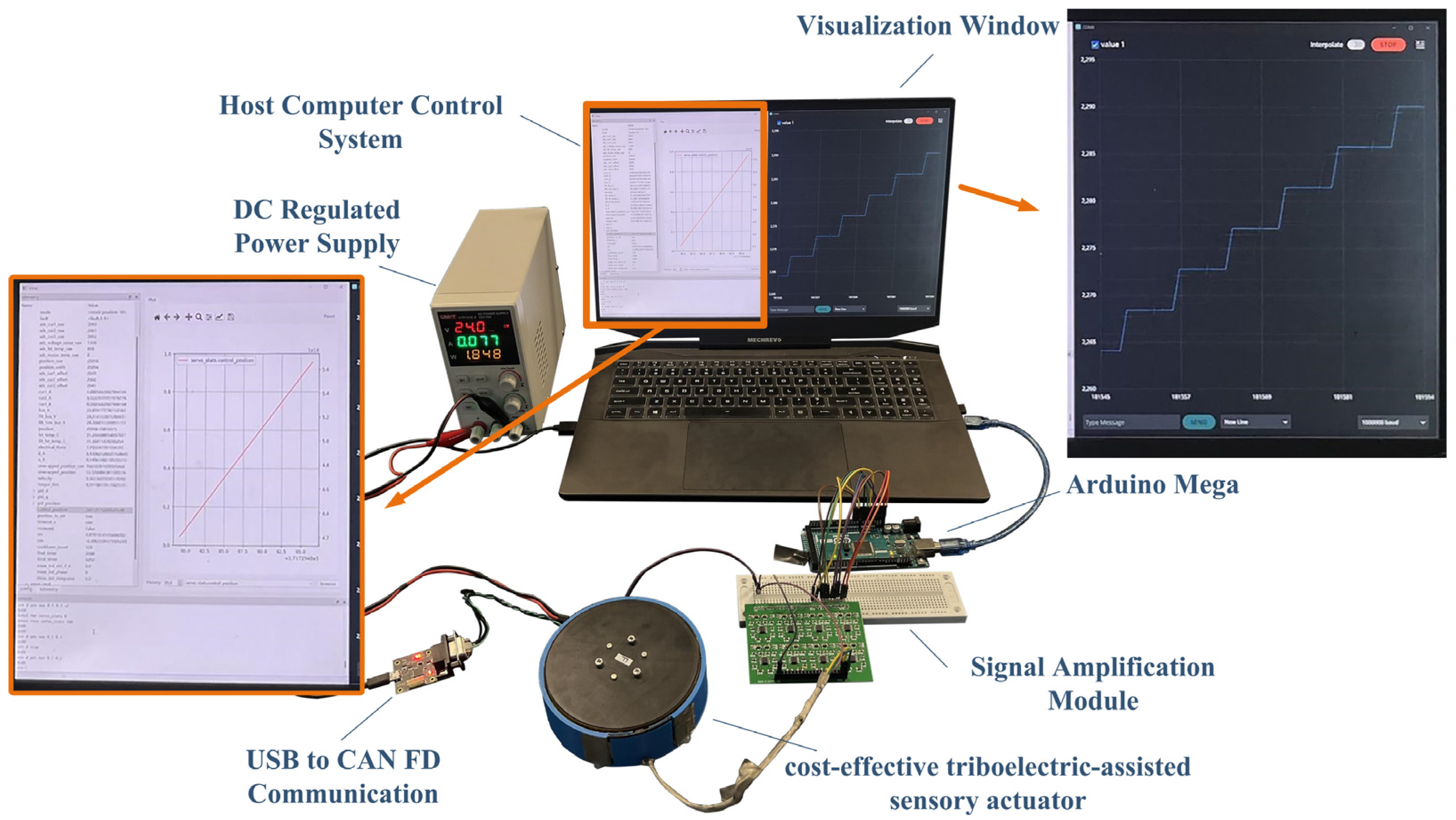
We have set up a workstation for data measurement, as shown in Figure 4. We power the motor using a DC power supply and facilitate communication between the host control system and the motor through a USB–CAN FD adapter. The operational amplifier module we designed consists of a voltage regulation circuit with an AMS1117 and six operational amplifier circuits with LMS358, supporting the simultaneous amplification of multiple signals. The amplified signals are received by an Arduino Mega series micro-controller, allowing real-time observation and data saving through a visualization window.
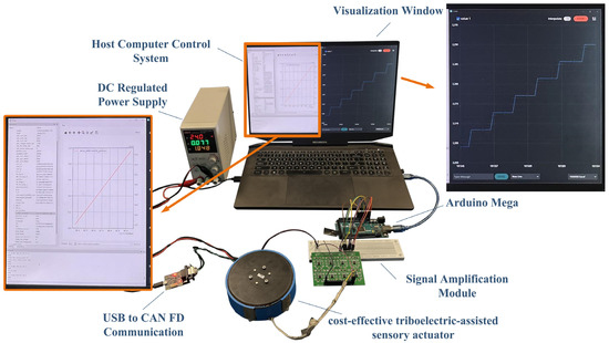
Figure 4.
Data measurement workstation.
3. Results and Discussion
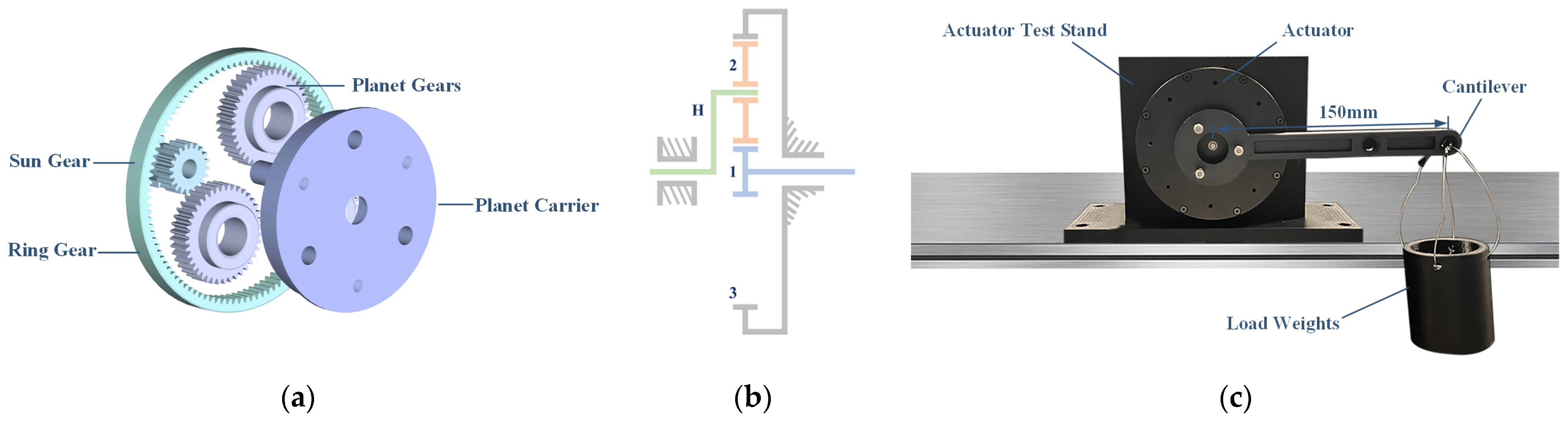
The backdrivability of actuators is crucial in fields such as robotics. For instance, in human exoskeletons, actuators need to assist movements based on human actions. In such scenarios, the human must initially drive the actuator, which then provides auxiliary support. To ensure smooth human motion, actuators must possess excellent backdrivability, and a lower transmission ratio results in a smaller back-driving torque [6]. As shown in Figure 5a,b, the reducer in the robot joint actuator we designed mainly consists of a sun gear, planet gears, a ring gear, and a planet carrier. The motor drives the sun gear to rotate, and after one stage of reduction, the planet carrier achieves a high-torque output. The transmission ratio calculation formula is as follows:

Figure 5.
Reduction mechanism in the actuator: (a) Reduction gear diagram. (b) Gear motion diagram, and in this picture, ‘H’ denotes the planet carrier of the planetary gear set, ‘1’ represents the sun gear within the planetary gear set, and ‘2’ refers to the planet gears of the planetary gear set. (c) back-drive torque measuring device.
After simplification, the following can be obtained:
The transmission ratio of this actuator is only 6:1. Using low gear ratio transmission can achieve low impedance in certain exoskeleton robots, minimizing resistance to natural human movement [6,27]. Additionally, for some lightweight intelligent robots, studies have shown that a low transmission ratio can effectively support dynamic robotic motion [28,29].
As shown in Figure 5c, to measure the back-driving torque of the actuator, we designed a lever measurement device. The device consists of a test bench, an actuator, a cantilever, and a bucket that can be loaded with weights. Taking the weight of the device itself into account, we first measured the weights of the cantilever and the empty bucket separately before testing. During the test, the cantilever was set to a horizontal position while weights were gradually added into the bucket. When the actuator just began to move, causing the cantilever to deviate from the horizontal, the total weight of the loaded weights was recorded. Through comprehensive calculations considering the masses of the cantilever, the empty bucket, and the weights, the back-driving torque of the actuator was determined to be 0.143 Nm, which allows for easy back-driving by the human body, meeting the requirements for applications such as human exoskeletons.
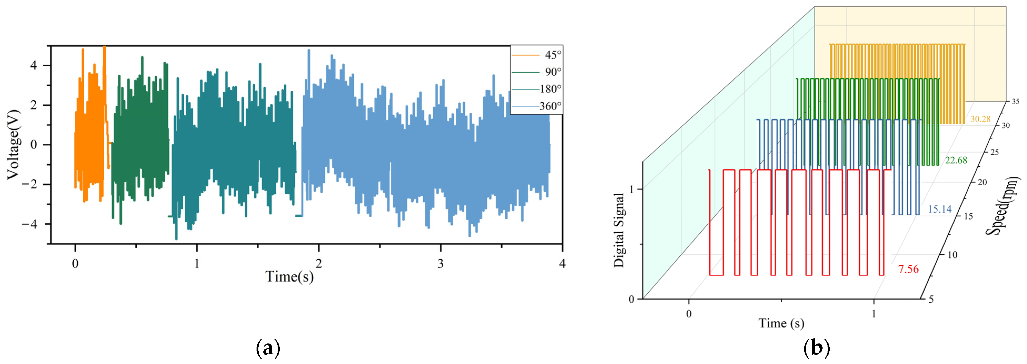
In order to verify that the sensor has a high displacement measurement accuracy for different rotation angles, we control the motor speed as a fixed value and carry out multiple experiments with the rotation angle as a single variable. As shown in Figure 6a, when the motor rotates at angles of 45°, 90°, 180°, and 360°, the triboelectric sensor outputs the corresponding raw sine voltage signals. By shaping the square wave, the rotation angles can be calculated. The rotation angles measured by the triboelectric sensor are 45.41°, 87.57°, 175.14°, and 356.76°, with an average error of only 1.8%.
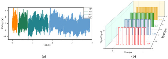
Figure 6.
Results of measurement: (a) The original triboelectric signals and measurement results of the angle. (b) Measurement results of the speed.
For the measurement of rotation speed accuracy, we control the motor to rotate at different speeds and compare the theoretical rotation speeds with the speeds measured by the sensor per unit time. As shown in Figure 6b, when the motor rotates at speeds of 7.5 rpm, 15 rpm, 22.5 rpm, and 30 rpm, the processed signals produce square waves per unit time. Calculating the average rotation speed, the triboelectric sensor measures average speeds of 7.56 rpm, 15.14 rpm, 22.68 rpm, and 30.28 rpm, with an average error of only 0.88%, indicating high accuracy in measuring average rotation speed.
Considering the factors affecting displacement and rotation speed accuracy, the following points are noted:
- When measuring environmental noise to eliminate external influences, if the environmental noise fluctuations are significant, the obtained raw waveform will also fluctuate accordingly, reducing the accuracy of the obtained square wave.
- The micro-slide used to detect the rotation direction may affect the sensor’s measurement accuracy due to the commutation gap that exists during start and commutation.
In this design, we performed a detailed cost analysis of the actuator’s angle-sensing component. Excluding the expenses for the circuit board, micro-controller, and other key electronic components, the raw material cost for the angle-sensing part is only approximately 8 RMB, while the total cost for the entire sensor system is about 313 RMB. Compared with conventional solutions that typically use high-precision (but more expensive) optical or magnetic encoders, our design achieves a significant cost reduction while still meeting the requirements for low-precision applications. The detailed cost breakdown is provided in Table 1.

Table 1.
Bill of materials for sensing module.
4. Conclusions
The triboelectric-based sensing system achieves a back-drive torque of 0.143 Nm, with angular measurement accuracy constrained to 1.8% deviation and speed measurement errors averaging 0.88%. These performance characteristics make it suitable for applications that do not require high precision, such as exoskeleton assistive devices, agricultural robots, and oil pipeline inspection robots. Furthermore, compared with traditional high-cost sensor system solutions, the total cost of the sensor components of the system is only about 313 yuan, showing excellent cost-effectiveness and suggesting a viable paradigm for future sensor system development in robotic joint actuation.
Author Contributions
Conceptualization, H.L.; methodology, H.L.; software, G.Z.; validation, H.L., G.Z. and Y.C.; investigation, H.L., G.Z. and Y.C.; resources, Y.Z.; data curation, Y.C.; writing—original draft preparation, H.L., G.Z. and Y.C.; writing—review and editing, H.L., G.Z., Y.C. and X.L.; visualization, H.L., G.Z., Y.C. and Y.Z.; supervision, T.C., X.L. and M.Z.; project administration, T.C., X.L. and M.Z.; funding acquisition, T.C, X.L and M.Z. All authors have read and agreed to the published version of the manuscript.
Funding
This research was funded by the Jiangsu Policy Guidance Program (International Science and Technology Cooperation) and the Belt and Road Initiative Innovative Cooperation Projects (Grant No. BZ2021016).
Institutional Review Board Statement
Not applicable.
Informed Consent Statement
Not applicable.
Data Availability Statement
Not applicable.
Acknowledgments
Thanks to the support from the School of Mechanical and Electrical Engineering of Soochow University, as well as the School of Future Science and Engineering of Soochow University.
Conflicts of Interest
The authors declare no conflicts of interest.
References
- El-Atab, N.; Mishra, R.B.; Al-Modaf, F.; Joharji, L.; Alsharif, A.A.; Alamoudi, H.; Diaz, M.; Qaiser, N.; Hussain, M.M. Soft Actuators for Soft Robotic Applications: A Review. Adv. Intell. Syst. 2020, 2, 2000128. [Google Scholar] [CrossRef]
- Gu, G.-Y.; Zhu, J.; Zhu, L.-M.; Zhu, X. A survey on dielectric elastomer actuators for soft robots. Bioinspiration Biomim. 2017, 12, 011003. [Google Scholar] [CrossRef]
- Vanderborght, B.; Albu-Schaeffer, A.; Bicchi, A.; Burdet, E.; Caldwell, D.G.; Carloni, R.; Catalano, M.; Eiberger, O.; Friedl, W.; Ganesh, G.; et al. Variable impedance actuators: A review. Robot. Auton. Syst. 2013, 61, 1601–1614. [Google Scholar] [CrossRef]
- Lim, H.-o.; Takanishi, A. Biped walking robots created at Waseda University: WL and WABIAN family. Philos. Trans. R. Soc. A Math. Phys. Eng. Sci. 2007, 365, 49–64. [Google Scholar] [CrossRef] [PubMed]
- Pratt, G.A.; Williamson, M.M. Series elastic actuators. In Proceedings of the 1995 IEEE/RSJ International Conference on Intelligent Robots and Systems. Human Robot Interaction and Cooperative Robots, Pittsburgh, PA, USA, 5–9 August 1995; Volume 391, pp. 399–406. [Google Scholar]
- Yu, S.Y.; Huang, T.H.; Yang, X.L.; Jiao, C.H.; Yang, J.F.; Chen, Y.; Yi, J.G.; Su, H. Quasi-Direct Drive Actuation for a Lightweight Hip Exoskeleton With High Backdrivability and High Bandwidth. IEEE-ASME Trans. Mechatron. 2020, 25, 1794–1802. [Google Scholar] [CrossRef] [PubMed]
- Yang, C.; Yu, L.; Xu, L.; Yan, Z.; Hu, D.; Zhang, S.; Yang, W. Current developments of robotic hip exoskeleton toward sensing, decision, and actuation: A review. Wearable Technol. 2022, 3, e15. [Google Scholar] [CrossRef] [PubMed]
- Bajpai, A.; Carrasquillo, C.; Carlson, J.; Park, J.; Iyengar, D.; Herrin, K.; Young, A.J.; Mazumdar, A. Design and Validation of a Versatile High Torque Quasidirect Drive Hip Exoskeleton. IEEE-ASME Trans. Mechatron. 2024, 29, 789–797. [Google Scholar] [CrossRef]
- Das, S.; Chakraborty, B. Design and Realization of an Optical Rotary Sensor. IEEE Sens. J. 2018, 18, 2675–2681. [Google Scholar] [CrossRef]
- Kumar, A.S.A.; George, B.; Mukhopadhyay, S.C. Technologies and Applications of Angle Sensors: A Review. IEEE Sens. J. 2021, 21, 7195–7206. [Google Scholar] [CrossRef]
- Sinova, J.; Valenzuela, S.O.; Wunderlich, J.; Back, C.; Jungwirth, T. Spin hall effects. Rev. Mod. Phys. 2015, 87, 1213–1260. [Google Scholar] [CrossRef]
- Deak, J.; Jin, I. A High-Field Tunneling Magnetoresistive Angle Sensor. In Proceedings of the 2018 IEEE International Magnetics Conference (INTERMAG), Singapore, 23–27 April 2018; p. 1. [Google Scholar]
- Meng, X.; Sun, S.; Yan, X.; Yang, P.; Liu, F.; Cao, L. A Novel Circular Position Sensitive Detector for Continuously High-Precision Angle Measurement. In Proceedings of the 2023 24th International Conference on Electronic Packaging Technology (ICEPT), Tianjin, China, 8–11 August 2023; pp. 1–4. [Google Scholar]
- Nakamoto, H.; Ootaka, H.; Tada, M.; Hirata, I.; Kobayashi, F.; Kojima, F. Stretchable Strain Sensor with Anisotropy and Application for Joint Angle Measurement. IEEE Sens. J. 2016, 16, 3572–3579. [Google Scholar] [CrossRef]
- Manchi, P.; Graham, S.A.; Paranjape, M.V.; Kurakula, A.; Kavarthapu, V.S.; Yu, J.S. Calcium copper titanate incorporated polydimethylsiloxane flexible composite film-based triboelectric nanogenerator for energy harvesting and self-powered sensing applications. J. Mater. Sci. Technol. 2024, 190, 56–66. [Google Scholar] [CrossRef]
- Lee, D.; Chae, J.; Cho, S.; Kim, J.W.; Ahmad, A.; Karim, M.R.; La, M.; Park, S.J.; Choi, D. Bidirectional rotating direct-current triboelectric nanogenerator with self-adaptive mechanical switching for harvesting reciprocating motion. Int. J. Extrem. Manuf. 2024, 6, 12. [Google Scholar] [CrossRef]
- Qin, L.C.; Zhang, L.F.; Feng, J.G.; Zhang, F.B.; Han, Q.K.; Qin, Z.Y.; Chu, F.L. A hybrid triboelectric-piezoelectric smart squirrel cage with self-sensing and self-powering capabilities. Nano Energy 2024, 124, 12. [Google Scholar] [CrossRef]
- Huang, Y.; Li, Y.; Yang, Y.X.; Wu, Y.B.; Shi, Q.S. Flexible piezoelectric sensor based on polyvinylidene fluoride/polyacrylonitrile/carboxy-terminated multi-walled carbon nanotube composite films for human motion monitoring. Nanotechnology 2024, 35, 14. [Google Scholar] [CrossRef]
- Lu, L.J.; Ding, W.Q.; Liu, J.Q.; Yang, B. Flexible PVDF based piezoelectric nanogenerators. Nano Energy 2020, 78, 22. [Google Scholar] [CrossRef]
- Masoumi, S.; Shokrani, M.; Aghili, S.; Hossein-Babaei, F. Zinc oxide-based direct thermoelectric gas sensor for the detection of volatile organic compounds in air. Sens. Actuators B Chem. 2019, 294, 245–252. [Google Scholar] [CrossRef]
- Park, H.; Lee, D.; Park, G.; Park, S.; Khan, S.; Kim, J.; Kim, W. Energy harvesting using thermoelectricity for IoT (Internet of Things) and E-skin sensors. J. Phys. Energy 2019, 1, 042001. [Google Scholar] [CrossRef]
- Sun, Z.; Zhu, M.; Zhang, Z.; Chen, Z.; Shi, Q.; Shan, X.; Yeow, R.C.H.; Lee, C. Artificial Intelligence of Things (AIoT) Enabled Virtual Shop Applications Using Self-Powered Sensor Enhanced Soft Robotic Manipulator. Adv. Sci. 2021, 8, 2100230. [Google Scholar] [CrossRef]
- Zhu, M.L.; Sun, Z.D.; Chen, T.; Lee, C.K. Low cost exoskeleton manipulator using bidirectional triboelectric sensors enhanced multiple degree of freedom sensory system. Nat. Commun. 2021, 12, 16. [Google Scholar] [CrossRef]
- Quigley, M.; Brewer, R.; Soundararaj, S.P.; Pradeep, V.; Le, Q.; Ng, A.Y. Low-cost accelerometers for robotic manipulator perception. In Proceedings of the 2010 IEEE/RSJ International Conference on Intelligent Robots and Systems, Taipei, Taiwan, 18–22 October 2010; pp. 6168–6174. [Google Scholar]
- Wang, Z.; An, J.; Nie, J.; Luo, J.; Shao, J.; Jiang, T.; Chen, B.; Tang, W.; Wang, Z.L. A Self-Powered Angle Sensor at Nanoradian-Resolution for Robotic Arms and Personalized Medicare. Adv. Mater. 2020, 32, 2001466. [Google Scholar] [CrossRef] [PubMed]
- Singh, A.; Gopal, K.; Goswami, Y.; Kundu, M.; Varshney, P. Terahertz field generation from laser interaction with spherical nano-particles: Effect of external magnetic field. Opt. Quantum Electron. 2024, 56, 199. [Google Scholar] [CrossRef]
- Seok, S.; Wang, A.; Otten, D.; Kim, S. Actuator design for high force proprioceptive control in fast legged locomotion. In Proceedings of the 2012 IEEE/RSJ International Conference on Intelligent Robots and Systems, Algarve, Portugal, 7–12 October 2012; pp. 1970–1975. [Google Scholar]
- Kim, J.; Kang, T.; Song, D.; Yi, S.-J. Design and Control of a Open-Source, Low Cost, 3D Printed Dynamic Quadruped Robot. Appl. Sci. 2021, 11, 3762. [Google Scholar] [CrossRef]
- Howard, I.S. Design and Kinematic Analysis of a 3D-Printed 3DOF Robotic Manipulandum. In Towards Autonomous Robotic Systems; Springer: Cham, Switzerland, 2023; pp. 227–239. [Google Scholar]


Disclaimer/Publisher’s Note: The statements, opinions and data contained in all publications are solely those of the individual author(s) and contributor(s) and not of MDPI and/or the editor(s). MDPI and/or the editor(s) disclaim responsibility for any injury to people or property resulting from any ideas, methods, instructions or products referred to in the content. |
© 2025 by the authors. Licensee MDPI, Basel, Switzerland. This article is an open access article distributed under the terms and conditions of the Creative Commons Attribution (CC BY) license (https://creativecommons.org/licenses/by/4.0/).