Abstract
This paper focuses on the total harmonic distortion (THD) analysis of a multi-level inverter (MLI) for fuel cell applications. Furthermore, a 50 kW 625 V proton exchange membrane fuel cell (PEMFC) stack was employed for this analysis. The various modes of operation of the suggested inverter are presented accordingly, along with its switching combinations. Also, a sinusoidal pulse-width modulation (SPWM) controller was employed to drive the power electronic switches in the suggested topology. The suggested inverter can produce sinusoidal voltage with only fundamental frequency switching. Moreover, the number of components and voltage stress of the suggested topology are compared with the conventional topologies presented. In addition, the THD was analyzed with and without the LC filter. Finally, the validity of the system was verified through MATLAB/Simulink software R2022b.
1. Introduction
Advanced power electronic inverters are necessary to meet the high-power demands of electric vehicles (EVs) and hybrid electric vehicles [1,2]. The production of large electric drive trains for these vehicles would lead to increased fuel efficiency, lower emissions, and probably better performance of the vehicles [2,3].
Owing to their high VA ratings, multilevel inverters (MLIs) are uniquely appropriate for EV applications [3,4]. They can easily produce the desired voltage from multiple levels of DC voltage to provide suitable power for EV or HEV drives [5]. The produced output can be obtained using a staircase approach, depending on the incremental levels that lead to the required voltage waveform. Furthermore, if the number of levels increased in output waveform, this would help reduce the total harmonic distortion as well as stress across the power electronic components [6,7].
Furthermore, a suitable power electronic switch is required for high-power applications to meet industry requirements [8,9]. An insulated gate bipolar transistor (IGBT) has a high power rating and high-voltage stress features for use in high-frequency applications [10]. Thus, a metal–oxide semiconductor field-effect transistor (MOSFET) is a suitable component for high-frequency operation.
Nevertheless, its power rating is poor relative to an IGBT. Several different multilevel topologies use low-rating switches for high-power applications to solve this problem [11,12]. The benefits of multilevel topology are lower switching frequency, low dv/dt, and low-input current distortion. Hence, it is usually used in high-power applications [13].
In addition, it has been demonstrated that the inverter can choose a fundamental frequency switching pattern to create a nearly sinusoidal output while simultaneously maintaining the dc voltage level of the capacitors.
After rapid research, many structures and modifications have been developed in multi-level inverters. Among all topologies, the major structures are cascaded multi-level configurations, the neutral point (diode clamped), and the flying capacitor (capacitor clamped) [14]. A cascaded multi-level inverter can be used for increasing the number of levels owing to its modularization, ease of execution, and lower expense. Nevertheless, the cost of the system is increased due to its incremental levels and reduced inverter efficiency. In addition, the lower number of levels leads to considerably high values of the LC filter to mitigate the harmonics [15]. In [16], a single-phase seven-level transformer-less inverter was discussed; it seems a greater number of power electronic devices were utilized for each voltage response, leading to high power loss. An MLI technique was suggested in [17,18], which considered a single power switch and diode coupled with a traditional H-bridge in order to control each additional source of dc inputs. As a result, the component count increased and power-sharing between sources was unequal. Indeed, in [19], a modular MLI with a reduction in power electronic components and usage of excessive dc sources was suggested, but complexity in the controller made the execution slow to generate multilevel voltage responses.
The main objectives of the suggested topology are as follows:
- To produce sinusoidal voltage using only fundamental frequency switching.
- To reduce the power components of the suggested topology.
- To minimize the total harmonic distortion (THD) of the suggested topology.
2. Suggested Topology
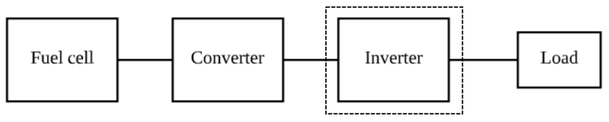
The fuel cell-based system is represented in the block diagram depicted in Figure 1. The fuel cell acts as an input for the corresponding system to operate the load. In this article, an effective inverter topology is suggested to meet the load demand. The suggested topology is used to generate the seven-level output.
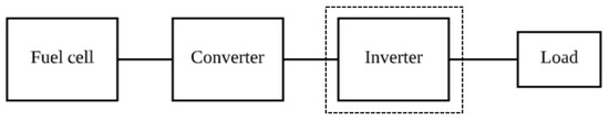
Figure 1.
Block diagram of fuel cell-based system.
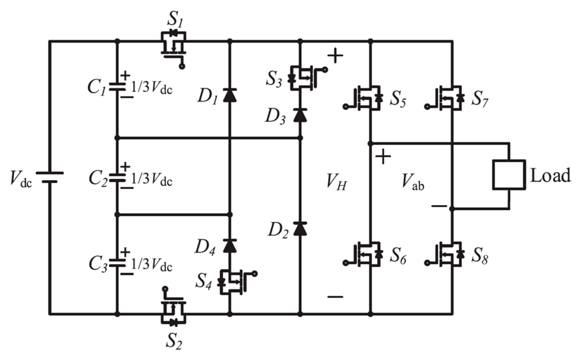
The suggested topology displayed in Figure 2 consists of three capacitors, C1, C2, and C3, connected in series, which are parallel to the dc source. The shared voltage among the capacitors is transferred to an H-bridge through four MOSFETs along with four diodes. In addition, the H-bridge is formed by two legs, with two MOSFETs for each leg, in order to produce a seven-level response with effective gating signals.
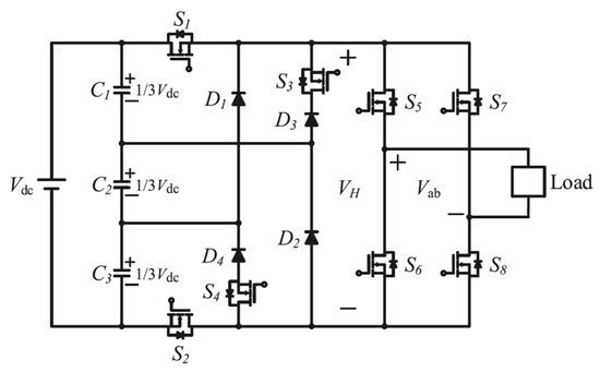
Figure 2.
Suggested seven-level inverter topology.
Modes of Operation
This topology is operated in seven modes to obtain the seven-level response; i.e., and 0 is as follows:
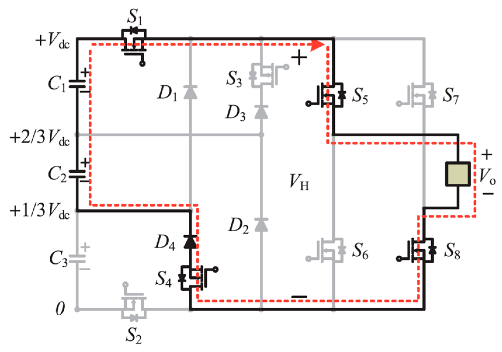
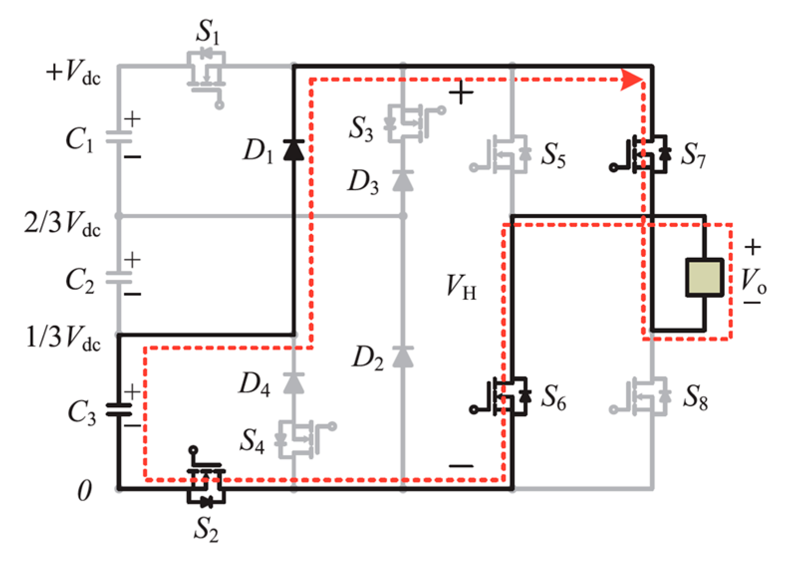
- In mode 1 operation, the capacitor discharges the energy to the load via S1, S5, S8, and D2 during the positive half cycle. The voltage response across the load is . The current direction is displayed in Figure 3.
 Figure 3. Mode 1 operation.
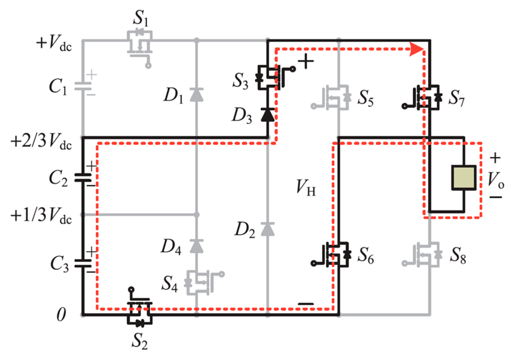
- In mode 2 operation, the voltage across capacitors C1 and C2 is transmitted to the load through switches S1, S5, S8, S4, and D4, and the voltage response is . The current direction is displayed in Figure 4.
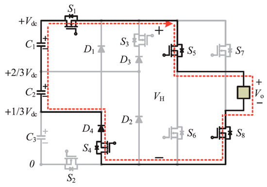 Figure 4. Mode 2 operation.
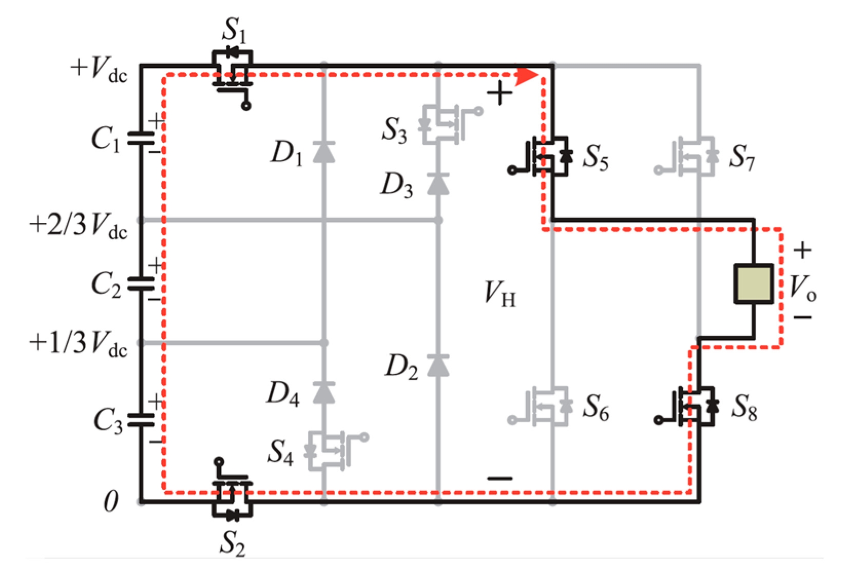
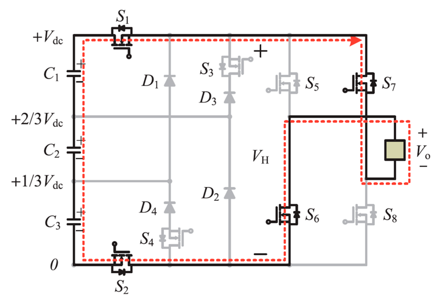
- In mode 3, the three capacitors’ (C1, C2, and C3) voltages are fed to the load via S1, S2, S5, and S8. The voltage response across the load is , and the corresponding current direction is displayed in Figure 5.
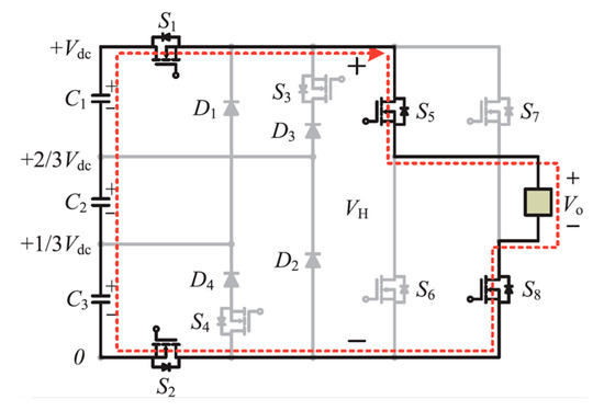 Figure 5. Mode 3 operation.
- In mode 4, during the negative half cycle capacitor C3 discharges the voltage to the load through switches D1, S7, S6, and S2. The voltage response across the load is , and its current direction is shown in Figure 6.
 Figure 6. Mode 4 operation.
- In mode 5, capacitors C2 and C3 provide voltage to the load through switches D3, S3, S7, S6, and S2. The corresponding voltage across the terminal is and its current direction is displayed in Figure 7.
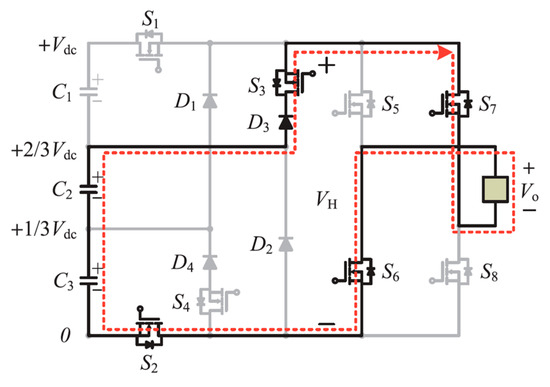 Figure 7. Mode 5 operation.
- In mode 6, all capacitors (C1, C2, and C3) produce voltage across the load as The current direction is displayed in Figure 8. During this mode of operation, the corresponding switches S1, S7, S6, and S2 are turned on.
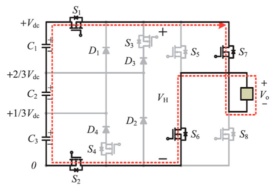 Figure 8. Mode 6 operation.
- In mode 7, the voltage generated across the load is zero. Switches S5 and S7 are turned on during this mode of operation. The corresponding current flow direction is displayed in Figure 9. The detailed switching combinations of seven-level response is shown in the Table 1 is as follows.
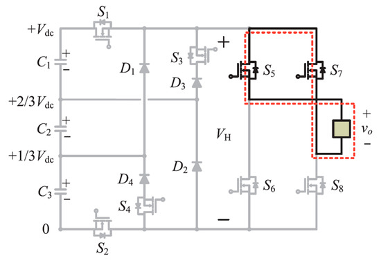 Figure 9. Mode 7 operation.
 Table 1. Switching combinations of the seven-level response.
3. Results and Discussion
In this study, the suggested topology was assessed using conventional seven-level inverter topologies [20,21] displayed in the following tables. The components required to generate a seven-level response of the inverters are shown in Table 2. The voltage stress of the suggested topology as compared with conventional topologies is presented in Table 3.
Table 2.
Components comparison of seven-level inverters.
Table 3.
Comparison of seven-level inverters’ voltage stresses.
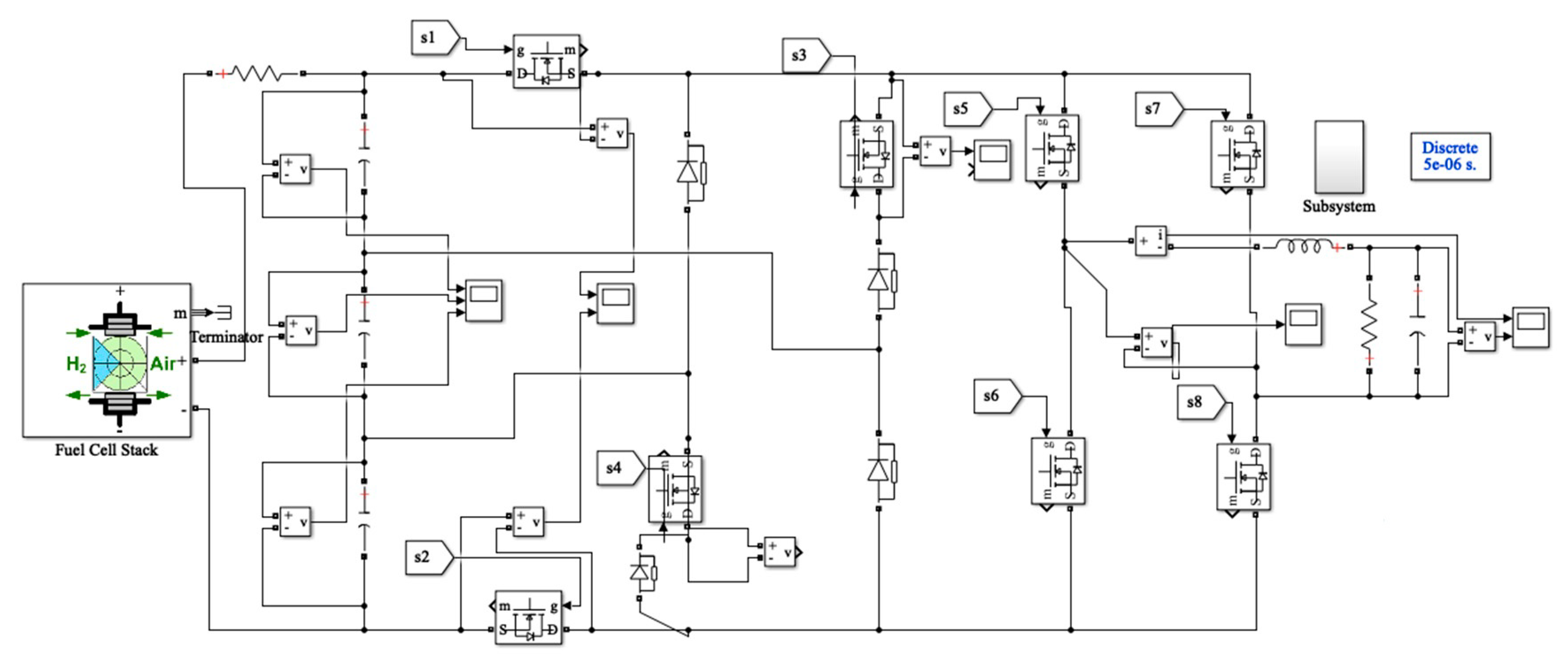
The suggested topology based on fuel cells implemented in Simulink software is presented in Figure 10. A 50 kW 625 V proton exchange membrane fuel cell (PEMFC) stack is used to generate a seven-level response for the MLI.

Figure 10.
Simulation model of suggested seven-level inverter.
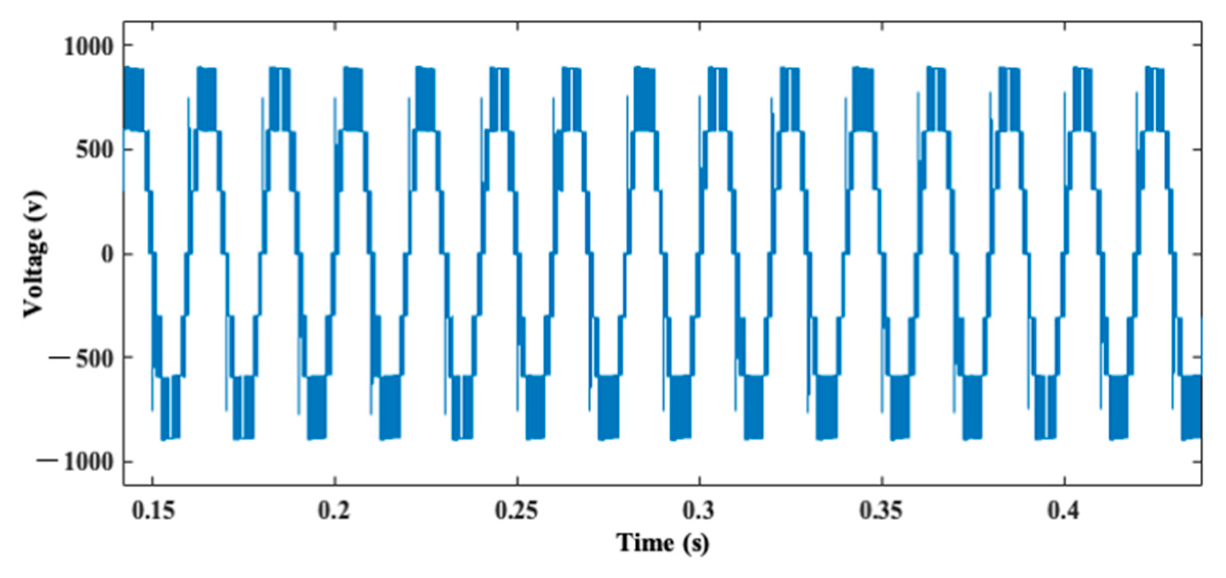
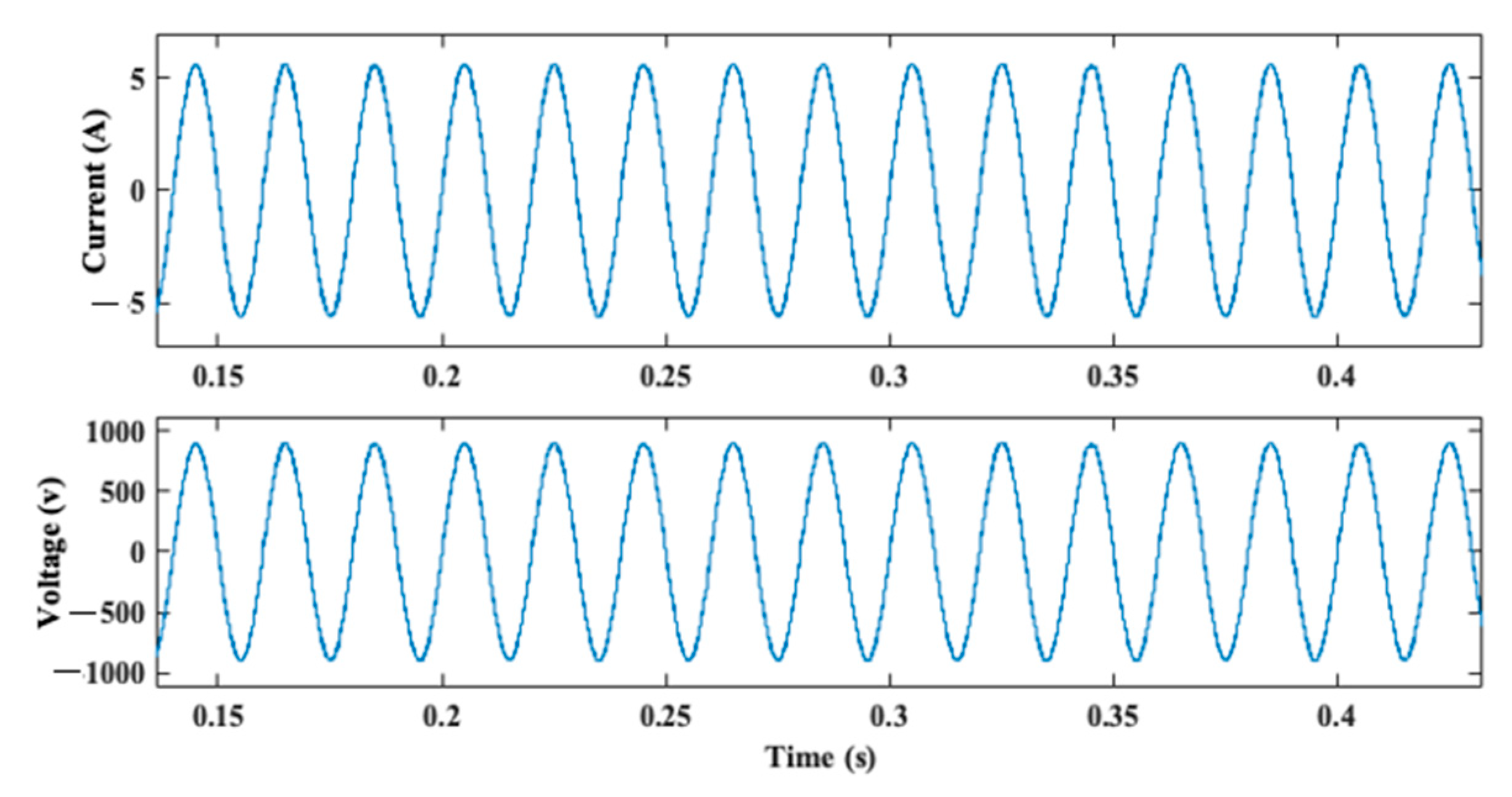
The seven-level AC output generated without the LC filter is depicted in Figure 11, and the corresponding response with the LC filter is displayed in Figure 12. It was observed that a voltage of 830 V obtained from a voltage of 625 V input seemed to boost this feature, and could be used for high voltage applications. The current response across the load was almost sinusoidal for a fundamental frequency of 50 Hz with an amplitude of 5.2 A. Simulation results show that the suggested inverter could generate the desired output voltage.
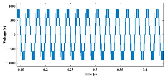
Figure 11.
Seven level response of inverter without LC filter.
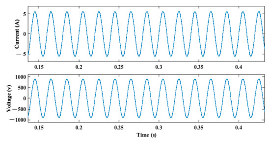
Figure 12.
Seven level responses of inverter with LC filter.
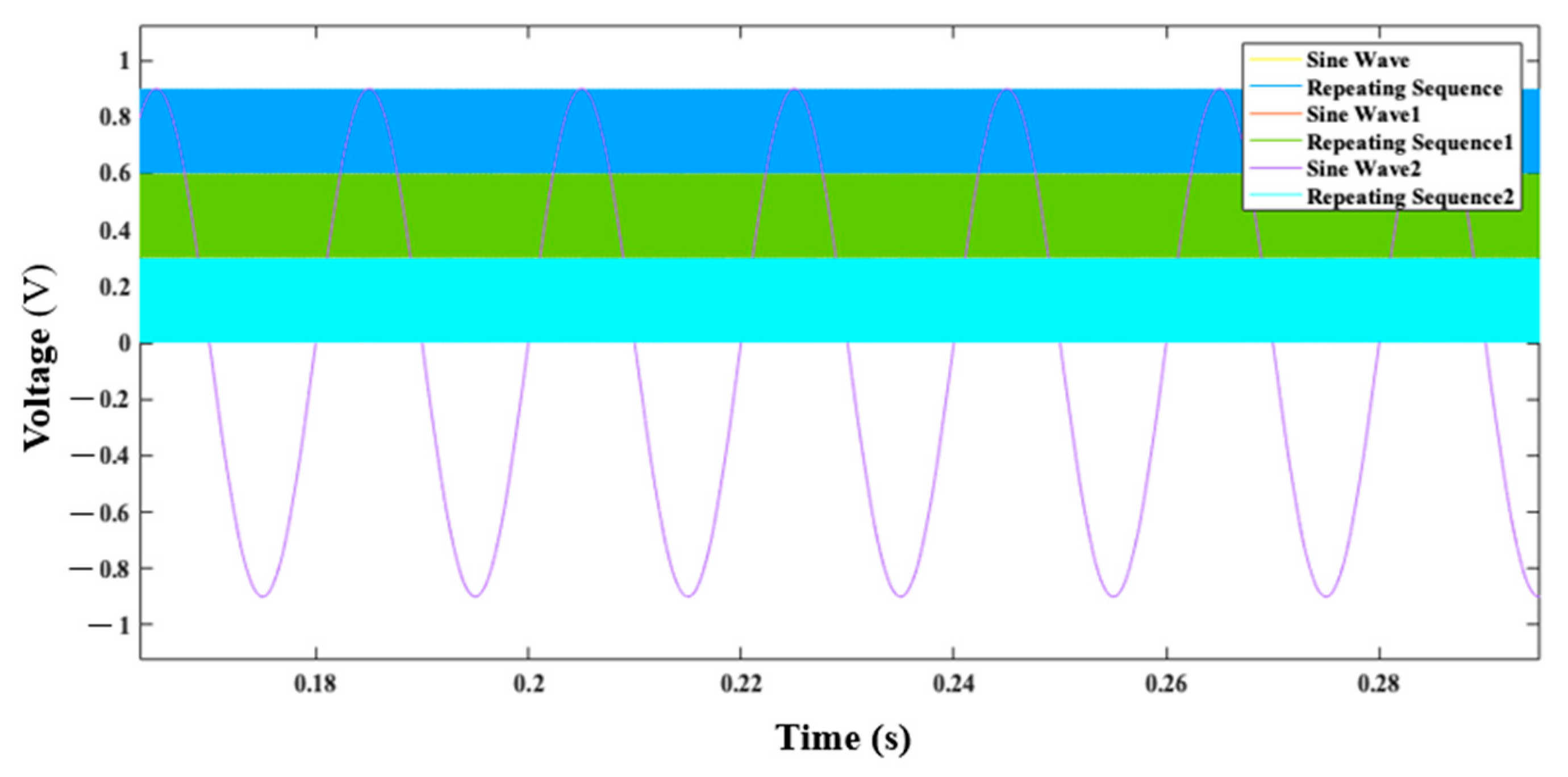
A SPWM was used in this study to generate a sinusoidal waveform by controlling the duty cycle of the pulse width-modulated signal. The SPWM controller implemented in this study to obtain the gating signals for the power electronic switches is shown in Figure 13 and Figure 14, respectively. It was based on the concept of comparing a reference sinusoidal waveform with a triangular waveform, which is typically a high-frequency triangular wave from. The widths of the pulses in the carrier waveform were adjusted in such a way that they matched the instantaneous value of the reference wave form, and the generated signal given to the power electronic switches of the suggested inverter is shown in Figure 13.
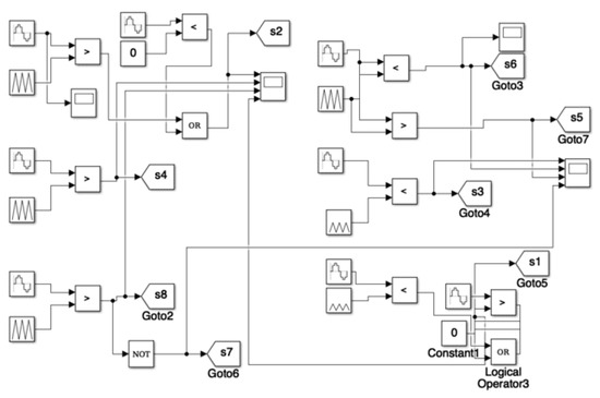
Figure 13.
Simulation model of PWM control algorithm.

Figure 14.
Voltage of PWM controller.
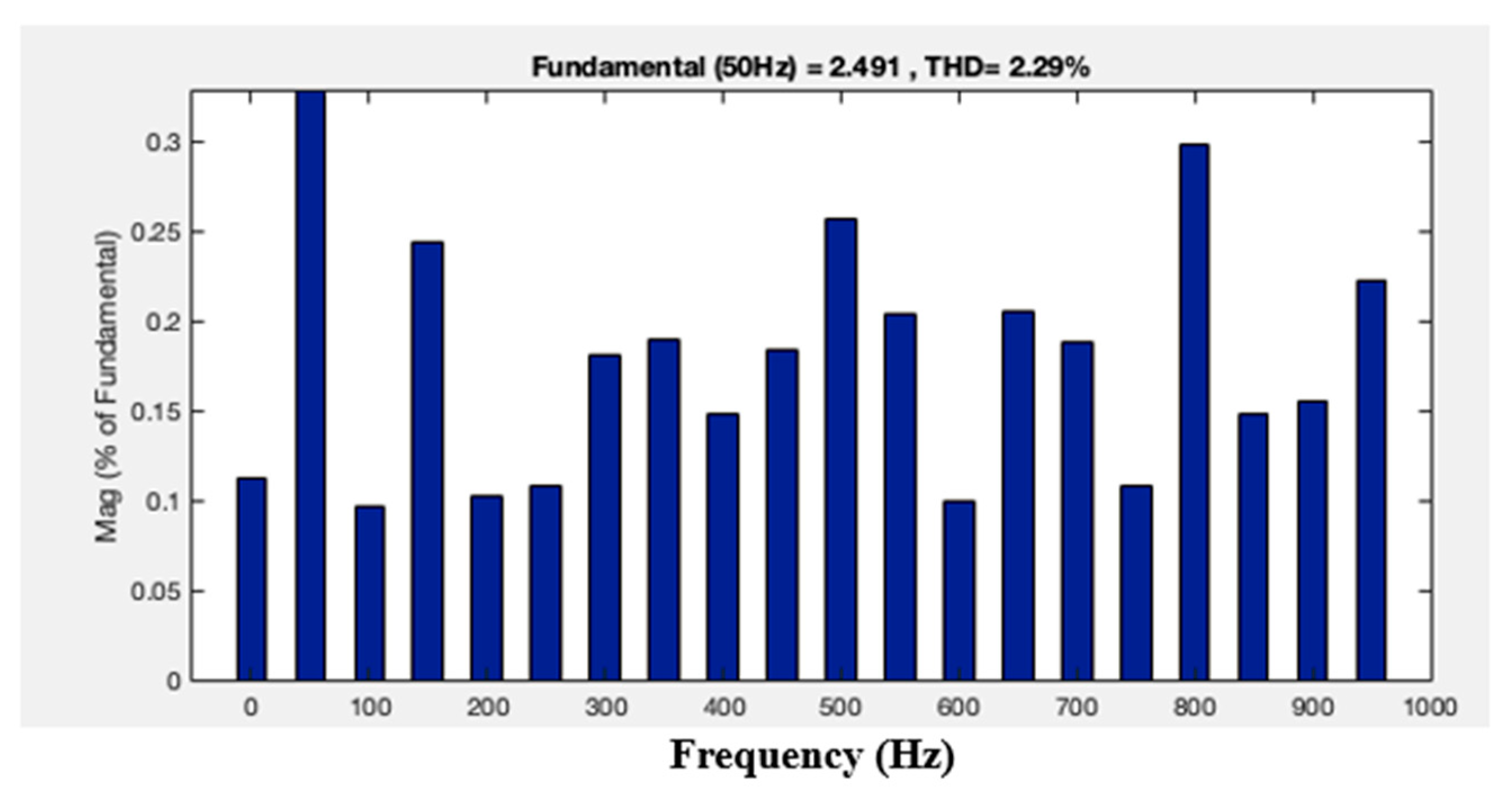
The suggested MLI, without and with the LC filter, had total harmonic distortions of 18.86% and 2.29%, respectively, as shown in Figure 15 and Figure 16. It was observed that the THD level was reduced when the MLI was connected to the LC filter.
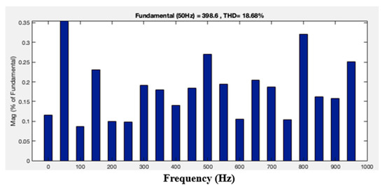
Figure 15.
Total harmonic distortion without LC filter.
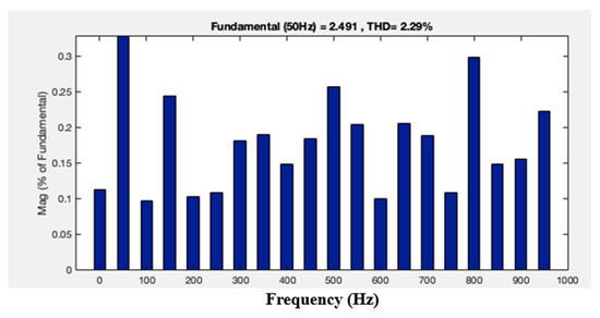
Figure 16.
Total harmonic distortion with LC filter.
4. Conclusions and Future Scope
A reduced-components MLI topology that could produce seven-level output was designed using the SPWM technique, and implemented using MATLAB/Simulink. The suggested MLI has the following advantages as compared with conventional inverters:
- The suggested topology with the minimum active number of components can be easily extended to nine-level or higher output.
- Owing to switching frequency at 50 Hz, switching losses nearly equal zero.
- The seven-level response is generated using one H-bridge.
- The number of capacitors utilized in this suggested topology is lower compared to those used in a conventional cascaded H-bridge multilevel inverter.
- The THD can be still reduced by increasing the number of levels, and using advanced PWM techniques can reduce loss.
Author Contributions
Conceptualization, A.S.V. and P.S.C.; methodology, A.S.V. and R.S.; software, A.S.V. and P.S.C.; validation, A.S.V., C.H.N.K. and R.S.; formal analysis, V.J.; investigation, A.S.V. and P.S.C.; resources, A.S.V.; data curation, A.S.V. and P.S.C.; writing—original draft preparation, A.S.V.; writing—review and editing, R.S., V.J. and C.H.N.K.; visualization, A.S.V. and P.S.C.; supervision, A.S.V. All authors have read and agreed to the published version of the manuscript.
Funding
This research received no external funding.
Institutional Review Board Statement
Not applicable.
Informed Consent Statement
Not applicable.
Data Availability Statement
Data that support the findings of this study are available from the corresponding author upon reasonable request.
Conflicts of Interest
The authors declare no conflicts of interest.
References
- Veerendra, A.S.; Mohamed, M.R.; Peddakapu, K.; Sekhar, C.P. Minimization of total harmonic distortion and enhancing voltage level for hybrid multilevel converter with different sources. Adv. Control Appl. Eng. Ind. Syst. 2020, 2, e58. [Google Scholar] [CrossRef]
- Veerendra, A.S.; Mohamed, M.R.; Sulaiman, M.H.; Sudhakar, K.; Peddakapu, K. Modelling and simulation of dual sourced front-end converter for hybrid electric vehicles. Int. J. Ambient. Energy 2020, 43, 1646–1653. [Google Scholar] [CrossRef]
- Tolbert, L.M.; Peng, F.Z.; Habetler, T.G. Multilevel inverters for electric vehicle applications. In Proceedings of the Power Electronics in Transportation (Cat. No. 98TH8349), Dearborn, MI, USA, 22–23 October 1998; IEEE: Piscataway, NJ, USA, 1998; pp. 79–84. [Google Scholar]
- Abu-Rub, H.; Holtz, J.; Rodriguez, J.; Ge, B. Medium-Voltage Multilevel Converters-State of the Art, Challenges, and Requirements in Industrial Applications. IEEE Trans. Ind. Electron. 2010, 57, 2581–2596. [Google Scholar] [CrossRef]
- Veerendra, A.S.; Mohamed, M.R.; Sulaiman, M.H.; Leung, P.K. Modeling and analysis of hybrid multilevel converter for constant DC and fuel cell sources. Energy Storage 2020, 2, e193. [Google Scholar] [CrossRef]
- Lukic, S.M.; Cao, J.; Bansal, R.C.; Rodriguez, F.; Emadi, A. Energy storage systems for automotive applications. IEEE Trans. Ind. Electron. 2008, 55, 2258–2267. [Google Scholar] [CrossRef]
- Kouro, S.; Malinowski, M.; Gopakumar, K.; Pou, J.; Franquelo, L.G.; Wu, B.; Rodriguez, J.; Pérez, M.A.; Leon, J.I. Recent Advances and Industrial Applications of Multilevel Converters. IEEE Trans. Ind. Electron. 2010, 57, 2553–2580. [Google Scholar] [CrossRef]
- Ali, A.I.M.; Sayed, M.A.; Mohame, E.E.M.; Azmy, A.M. Advanced Single-Phase Nine-Level Converter for the Integration of Multiterminal DC Supplies. IEEE J. Emerg. Sel. Top. Power Electron. 2019, 7, 1949–1958. [Google Scholar] [CrossRef]
- Babaei, E.; Laali, S.; Bayat, Z. A Single-Phase Cascaded Multilevel Inverter Based on a New Basic Unit with Reduced Number of Power Switches. IEEE Trans. Ind. Electron. 2015, 62, 922–929. [Google Scholar] [CrossRef]
- Shukla, A.; Ghosh, A.; Joshi, A. Flying-Capacitor-Based Chopper Circuit for DC Capacitor Voltage Balancing in Diode-Clamped Multilevel Inverter. IEEE Trans. Ind. Electron. 2010, 57, 2249–2261. [Google Scholar] [CrossRef]
- Li, H.; Gu, Y.; Zhang, X.; Liu, Z.; Zhang, L.; Zeng, Y. A Fault-Tolerant Strategy for Three-Level Flying-Capacitor DC/DC Converter in Spacecraft Power System. Energies 2023, 16, 556. [Google Scholar] [CrossRef]
- Muralikumar, K.; Ponnambalam, P. Analysis of cascaded multilevel inverter with a reduced number of switches for reduction of total harmonic distortion. IETE J. Res. 2023, 69, 295–308. [Google Scholar] [CrossRef]
- Rodriguez, J.; Lai, J.S.; Peng, F.Z. Multilevel inverters: A survey of topologies, controls, and applications. IEEE Trans. Ind. Electron. 2002, 49, 724–738. [Google Scholar] [CrossRef]
- Feloups, C.E.S.; Mohamed, E.E.M. A Novel Reduced Components Model Predictive Controlled Multilevel Inverter for Grid-Tied Applications. Adv. Electr. Electron. Eng. 2019, 17, 251–261. [Google Scholar] [CrossRef]
- Kuncham, S.K.; Annamalai, K.; Nallamothu, S. A new structure of single-phase two-stage hybrid transformerless multilevel PV inverter. Int. J. Circuit Theory Appl. 2019, 47, 152–174. [Google Scholar] [CrossRef]
- Manjunath, T.G.; Vikramathithan, A.C.; Girish, H. Analysis of Total Harmonic Distortion and implementation of Inverter Fault Diagnosis using Artificial Neural Network. J. Phys. Conf. Ser. 2022, 2161, 012060. [Google Scholar] [CrossRef]
- Ugwuagbo, E.; Balogun, A.; Ray, B.; Anwar, A.; Ugwuishiwu, C. Total Harmonics Distortion Prediction at the Point of Common Coupling of industrial load with the grid using Artificial Neural Network. Energy AI 2023, 14, 100281. [Google Scholar] [CrossRef]
- Kim, S.C.; Narasimha, S.; Salkuti, S.R. A new multilevel inverter with reduced switch count for renewable power applications. Int. J. Power Electron. Drive Syst. 2020, 11, 2145–2153. [Google Scholar] [CrossRef]
- Prabaharan, N.; Palanisamy, K. Analysis and integration of multilevel inverter configuration with boost converters in a photovoltaic system. Energy Convers. Manag. 2016, 128, 327–342. [Google Scholar] [CrossRef]
- Xia, C.L.; Gu, X.; Shi, T.N.; Yan, Y. Neutral-Point Potential Balancing of Three-Level Inverters in Direct-Driven Wind Energy Conversion System. IEEE Trans. Energy Convers. 2011, 26, 18–29. [Google Scholar] [CrossRef]
- Challa, R.V.; Mikkili, S.; Bonthagorla, P.K. Modeling, Controlling Approaches, Modulation Schemes, and Applications of Modular Multilevel Converter. J. Control Autom. Electr. Syst. 2023, 34, 189–215. [Google Scholar] [CrossRef]


Disclaimer/Publisher’s Note: The statements, opinions and data contained in all publications are solely those of the individual author(s) and contributor(s) and not of MDPI and/or the editor(s). MDPI and/or the editor(s) disclaim responsibility for any injury to people or property resulting from any ideas, methods, instructions or products referred to in the content. |
© 2023 by the authors. Licensee MDPI, Basel, Switzerland. This article is an open access article distributed under the terms and conditions of the Creative Commons Attribution (CC BY) license (https://creativecommons.org/licenses/by/4.0/).