
Sensitivity Analysis of Internally Reinforced Beams Subjected to Three-Point Bending Load †


Abstract
:1. Introduction
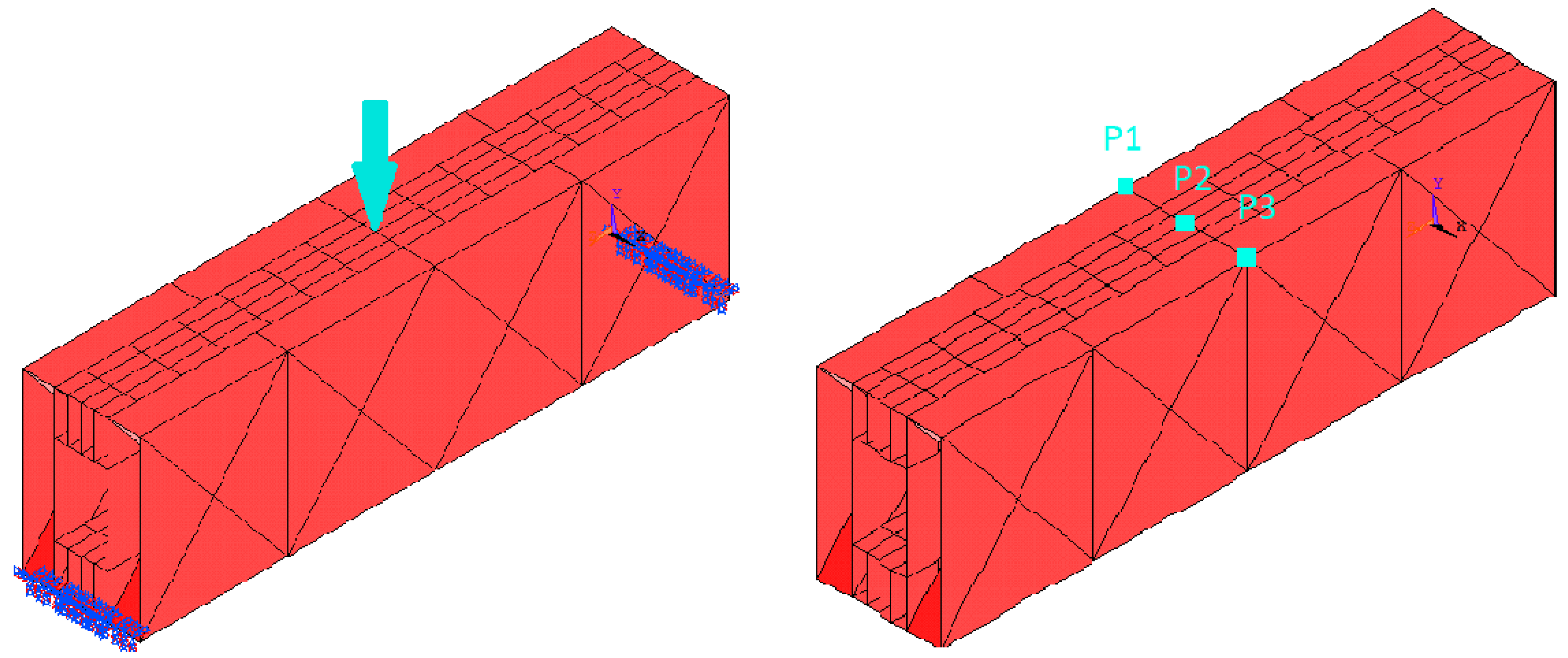
2. Materials and Methods
3. Results and Discussion
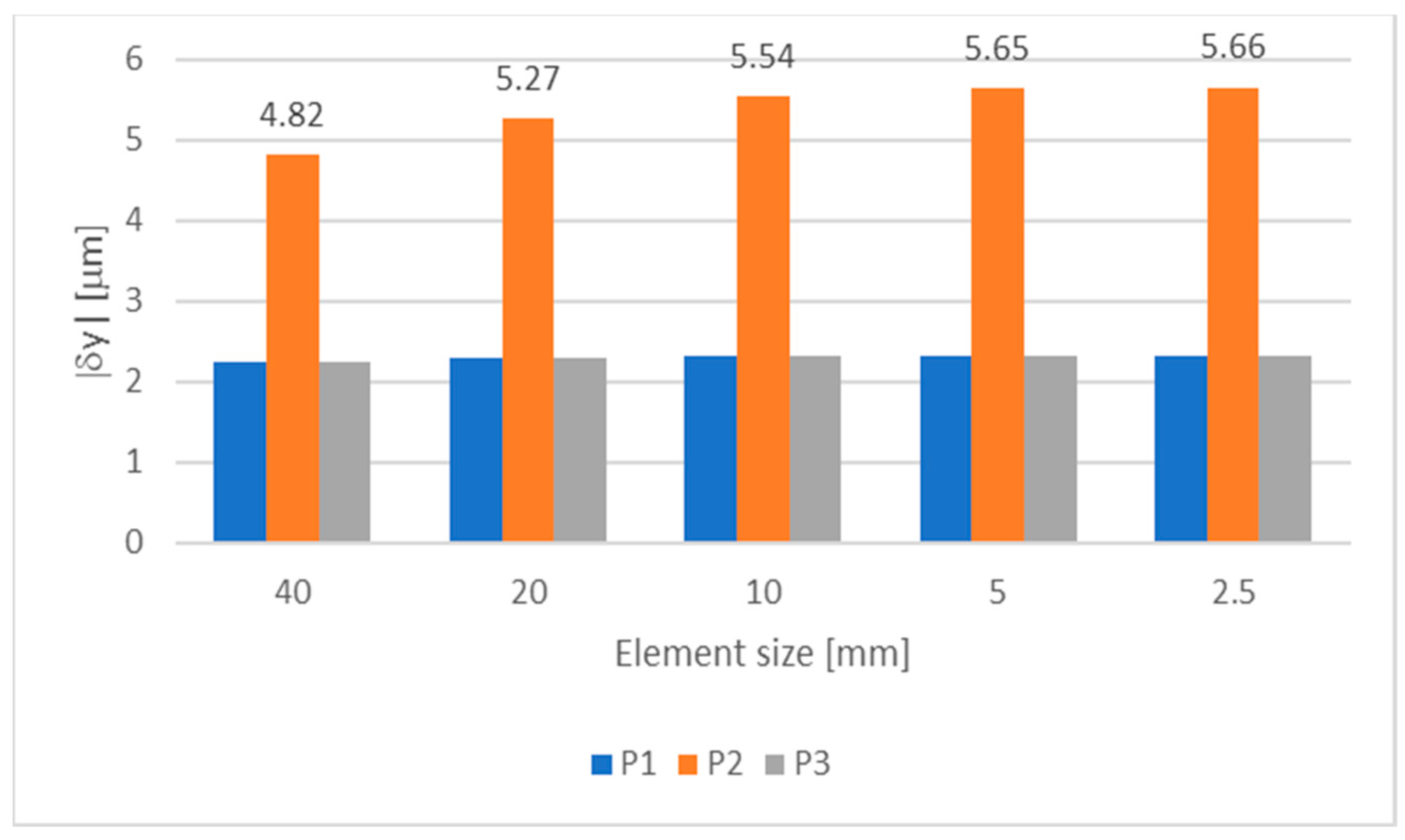
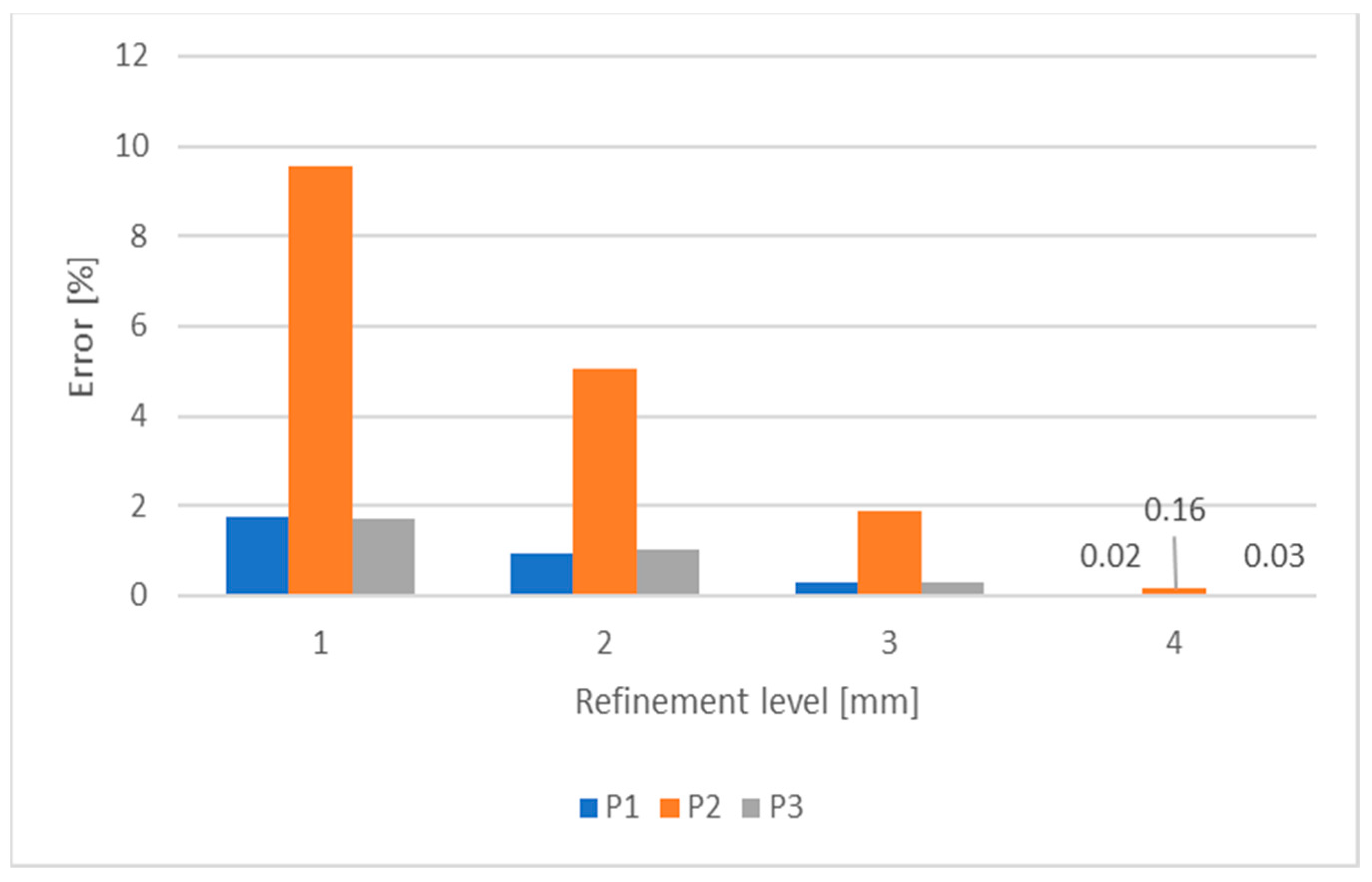
3.1. Mesh Convergence
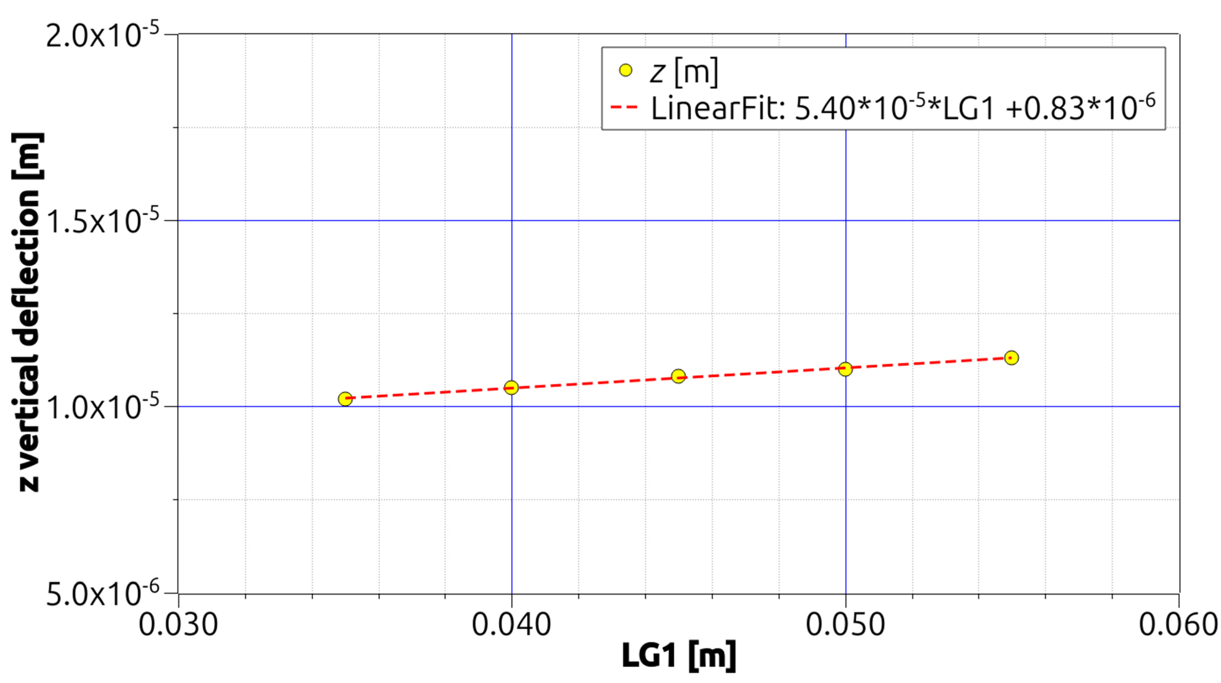
3.2. Sensitivity Analysis
4. Conclusions
Author Contributions
Funding
Institutional Review Board Statement
Informed Consent Statement
Data Availability Statement
Conflicts of Interest
References
- Silva, H.M. Optimization of the Mechanical Behavior of Hollow-Box Beams. Ph.D. Thesis, Lodz University of Technology, Lodz, Poland, 2018. [Google Scholar]
- Orlov, P. Fundamentals of Machine Design, 1st ed.; MIR Publishers: Moscow, Russia, 1976. [Google Scholar]
- Allen, H.G.; Neal, B.G. Analysis and Design of Structural Sandwich Panels; Elsevier: Amsterdam, The Netherlands, 1969. [Google Scholar]
- Vieira, D.G.; Meireles, J.F.; Nunes, J.P. Improving the Dynamical Behavior of a Laser Cutting Equipment by Using a Carbon. Mater. Sci. Forum 2013, 730–732, 349–354. [Google Scholar]
- Liu, Y. Design enhancement of thin-walled steel beams with improved stiffness and reduced weight. Int. J. Des. Eng. 2008, 1, 149–165. [Google Scholar] [CrossRef]
- Gosowski, B. Non-uniform torsion of stiffened open thin-walled members of steel structures. J. Constr. Steel Res. 2007, 63, 849–865. [Google Scholar] [CrossRef]
- Gosowski, B. Spatial stability of braced thin-walled members of steel structures. J. Constr. Steel Res. 2003, 59, 839–865. [Google Scholar] [CrossRef]
- Liu, Y.; Gannon, L. Finite element study of steel beams reinforced while under load. Eng. Struct. 2009, 31, 2630–2642. [Google Scholar] [CrossRef]
- Szewczak, R.; Smith, E.; DeWolf, J. Beams with Torsional Stiffeners. J. Struct. Eng. 1983, 109, 1635–1647. [Google Scholar] [CrossRef]


| j = 5 | j = 4 | j = 3 | j = 2 | j = 1 | |
| 0.055 | 0.05 | 0.045 | 0.04 | 0.035 | LG1 |
| 77.981 | 79.176 | 80.372 | 81.567 | 82.762 | mass (kg) |
| −2.29 × 10⁻⁶ | −2.18 × 10⁻⁶ | −2.06 × 10⁻⁶ | −1.95 × 10⁻⁶ | −1.84 × 10⁻⁶ | δyP1 (m) |
| −6.71 × 10⁻⁶ | −6.67 × 10⁻⁶ | −6.63 × 10⁻⁶ | −6.58 × 10⁻⁶ | −6.52 × 10⁻⁶ | δyP2 (m) |
| −2.29 × 10⁻⁶ | −2.18 × 10⁻⁶ | −2.06 × 10⁻⁶ | −1.95 × 10⁻⁶ | −1.84 × 10⁻⁶ | δyP3 (m) |
| 1.13 × 10⁻⁵ | 1.10 × 10⁻⁵ | 1.08 × 10⁻⁵ | 1.05 × 10⁻⁵ | 1.02 × 10⁻⁵ | δsum (m) |
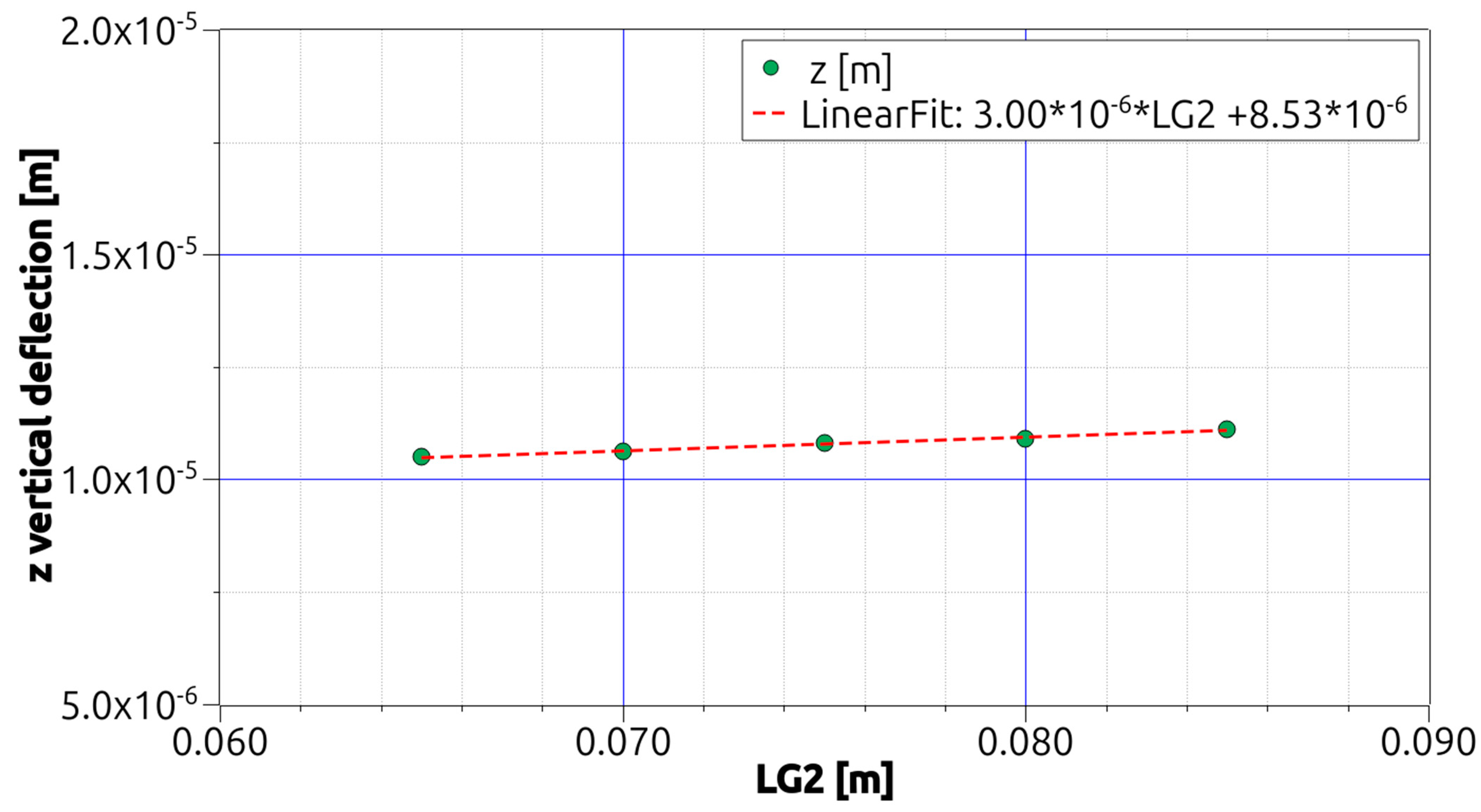
| j = 5 | j = 4 | j = 3 | j = 2 | j = 1 | |
| 0.085 | 0.08 | 0.075 | 0.07 | 0.065 | LG2 |
| 78.397 | 79.384 | 80.372 | 81.359 | 82.346 | mass (kg) |
| −2.10 × 10⁻⁶ | −2.08 × 10⁻⁶ | −2.06 × 10⁻⁶ | −2.04 × 10⁻⁶ | −2.02 × 10⁻⁶ | δyP1 (m) |
| −6.90 × 10⁻⁶ | −6.75 × 10⁻⁶ | −6.63 × 10⁻⁶ | −6.51 × 10⁻⁶ | −6.41 × 10⁻⁶ | δyP2 (m) |
| −2.10 × 10⁻⁶ | −2.08 × 10⁻⁶ | −2.06 × 10⁻⁶ | −2.04 × 10⁻⁶ | −2.02 × 10⁻⁶ | δyP3 (m) |
| 1.11 × 10⁻⁵ | 1.09 × 10⁻⁵ | 1.08 × 10⁻⁵ | 1.06 × 10⁻⁵ | 1.05 × 10⁻⁵ | δsum (m) |
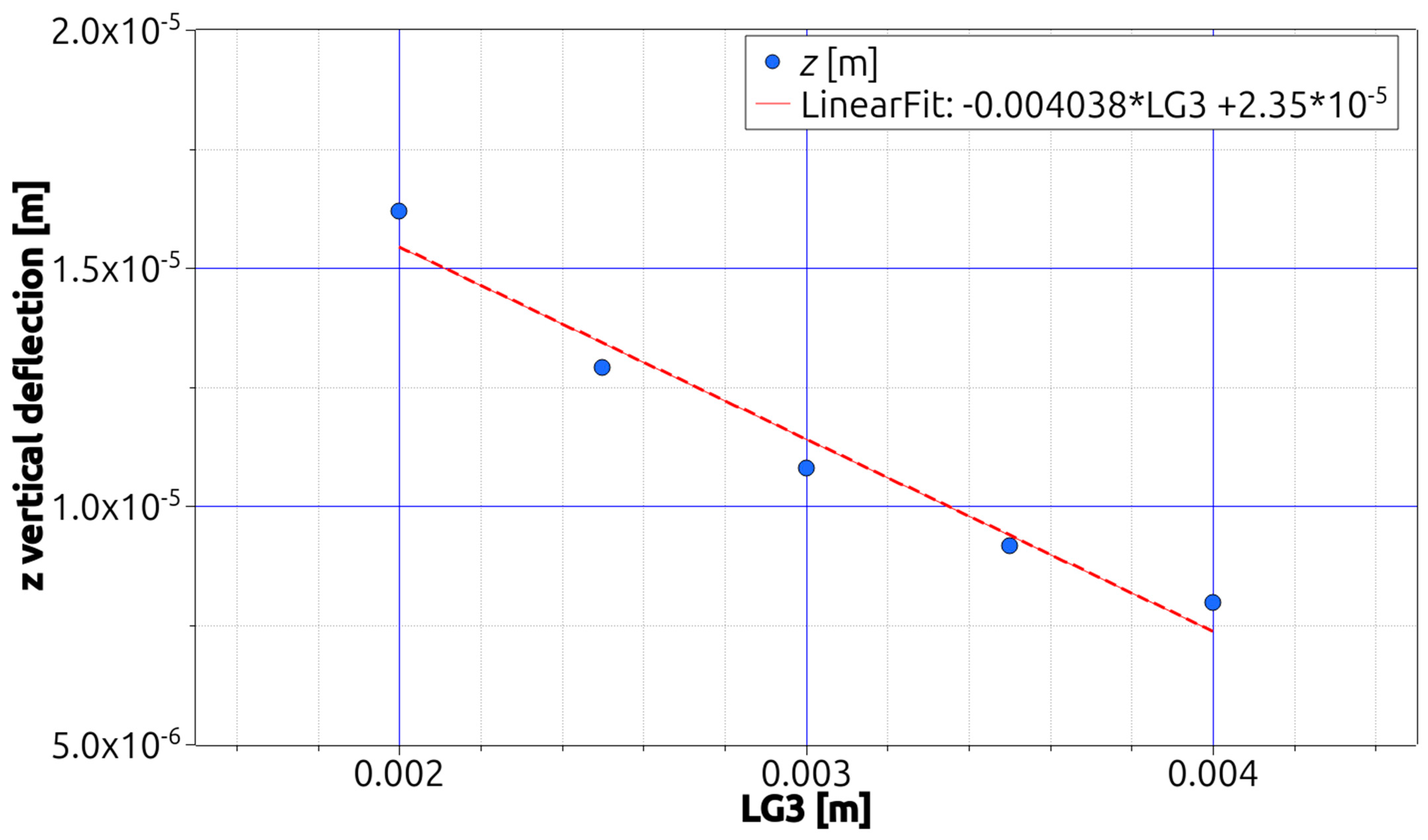
| j = 5 | j = 4 | j = 3 | j = 2 | j = 1 | |
| 0.004 | 0.0035 | 0.003 | 0.0025 | 0.002 | LG3 |
| 107.162 | 93.767 | 80.372 | 66.976 | 53.581 | mass (kg) |
| −1.65 × 10⁻⁶ | −1.84 × 10⁻⁶ | −2.06 × 10⁻⁶ | −2.34 × 10⁻⁶ | −2.67 × 10⁻⁶ | δyP1 (m) |
| −4.66 × 10⁻⁶ | −5.49 × 10⁻⁶ | −6.63 × 10⁻⁶ | −8.27 × 10⁻⁶ | −1.08 × 10⁻⁵ | δyP2 (m) |
| −1.65 × 10⁻⁶ | −1.84 × 10⁻⁶ | −2.06 × 10⁻⁶ | −2.34 × 10⁻⁶ | −2.67 × 10⁻⁶ | δyP3 (m) |
| 7.97 × 10⁻⁶ | 9.17 × 10⁻⁶ | 1.08 × 10⁻⁵ | 1.29 × 10⁻⁵ | 1.62 × 10⁻⁵ | δsum (m) |
Disclaimer/Publisher’s Note: The statements, opinions and data contained in all publications are solely those of the individual author(s) and contributor(s) and not of MDPI and/or the editor(s). MDPI and/or the editor(s) disclaim responsibility for any injury to people or property resulting from any ideas, methods, instructions or products referred to in the content. |
© 2023 by the authors. Licensee MDPI, Basel, Switzerland. This article is an open access article distributed under the terms and conditions of the Creative Commons Attribution (CC BY) license (https://creativecommons.org/licenses/by/4.0/).
Share and Cite
Silva, H.M.; Wojewoda, J. Sensitivity Analysis of Internally Reinforced Beams Subjected to Three-Point Bending Load. Eng. Proc. 2023, 56, 333. https://doi.org/10.3390/ASEC2023-15283
Silva HM, Wojewoda J. Sensitivity Analysis of Internally Reinforced Beams Subjected to Three-Point Bending Load. Engineering Proceedings. 2023; 56(1):333. https://doi.org/10.3390/ASEC2023-15283
Chicago/Turabian StyleSilva, Hugo Miguel, and Jerzy Wojewoda. 2023. "Sensitivity Analysis of Internally Reinforced Beams Subjected to Three-Point Bending Load" Engineering Proceedings 56, no. 1: 333. https://doi.org/10.3390/ASEC2023-15283
APA StyleSilva, H. M., & Wojewoda, J. (2023). Sensitivity Analysis of Internally Reinforced Beams Subjected to Three-Point Bending Load. Engineering Proceedings, 56(1), 333. https://doi.org/10.3390/ASEC2023-15283