Abstract
The General Lighthouse Authorities (GLA) R&D Directorate has, for some time, advocated that alternate position navigation and timing (PNT) systems should be established to offset critical dependency on Global Navigation Satellite Systems (GNSS), both in the maritime world and across wider industry. The maritime world already has a number of viable systems that may provide a ship’s navigator with position-fixing information independent of GNSS. A promising option is radar. Depending on size, merchant vessels are required to fit radar operating in the X-band (9 GHz) and, optionally S-band (3 GHz). The radar return from the shoreline provides a unique and identifiable fingerprint that depends on the location of the vessel. GRAD has developed a number of different processes that can convert a series of images from the ship’s radar into a series of output position-fixes, independent of having access to satellite (GNSS) positioning. This report describes the methods we investigated and presents the results from a number of ship trials.
1. Introduction
Global Navigation Satellite Systems (GNSS) are in use worldwide and form the de- facto standard for positioning, navigation and timing systems. GNSS technology is accurate, reliable and available globally, free at the point of use. This has led to it becoming an integral part of most industries, adopted as a silent utility across almost all sectors, resulting in a large amount of industrial activity now being critically dependent on its functioning [1].
GNSS, in particular the American GPS, is used extensively in the maritime world, primarily for plotting a vessel’s position on an electronic chart display (ECD) or ECDIS. It is also relied upon by other bridge equipment, such as for reporting a vessel’s position via AIS, and for timing purposes, such as for AIS transmission slots and digital selective calling (DSC). The advent of e-Navigation, integrated bridge systems and greater automation within the maritime sector will only increase the sector’s dependency on GNSS further.
GNSS signals are very weak, vulnerable to obstruction, local radio interference or deliberate jamming. The General Lighthouse Authorities (GLA) have, for a long time, advocated adopting alternate backup systems to mitigate the consequences of a potential loss of GNSS. The GLA Research & Development directorate (GRAD) has investigated a number of position-fixing technologies that operate independently of satellite systems, including making use of existing ship-borne equipment such as radar.
This paper provides a summary of our work on Radar Absolute Position Fixing and the results of our investigations so far.
2. Radar Absolute Position Fixing
SOLAS-class vessels are required to equip radar in the X-band (9 GHz) and, depending on size, also the S-band (3 GHz) [2]. Marine radar is a valuable tool for navigation; maintaining situational awareness; and collision avoidance, particularly in reduced-visibility conditions. There also exist a number of ways to employ a ship’s radar to determine the vessel’s position and to plot that position on a nautical chart [3]. A simple method is to pick several conspicuous landmarks such as headlands or radar-reflective beacons, to take range and bearing measurements off the radar screen, and plot these on the chart to determine a position. This is relatively easy to accomplish, but it requires the navigator’s time to determine the targets, to take measurements and to transfer these to the chart. It is repetitive and laborious work to complete by hand. Easier, time-saving measures such as parallel indexing from the shoreline can help.
An automated process would relieve the navigator of much of this burden, but an automated system may struggle to unambiguously determine radar-conspicuous targets on the screen and relate these to charted landmarks. We have looked at a number of different methods to automatically employ radar data to determine the position of the vessel, these are described below.
2.1. E-RACON Positioning
A RACON is a radar beacon, a device that listens for the signature emission of a ship’s radar and responds with a series of pulses on the same frequency. This “paints” a distinctive Morse code character on the interrogating ship’s radar screen and can enhance the visibility of an Aid to Navigation (AtoN). An “e-RACON” is a device that operates in an almost identical way to a conventional RACON except it is able to send digitally encoded data in its Morse paint to a suitably equipped New Technology (NT) radar. This information includes the precise surveyed latitude and longitude of the beacon. The technology is transparent to conventional radars that do not decode the data but see only the expected Morse character that appears on the screen.
By measuring the range and bearing to one or more e-RACONs, the radar can then determine its own position. The accuracy with which a radar system can determine the range to a target is considerably better, usually a few meters [4], than its ability to determine the bearing angle. A bearing error of a quarter of one degree equates to a position uncertainty of about 40 m at five Nautical Miles from the beacon and 100 m at 12 Nautical Miles. Figure 1 shows the results of some GRAD trials of the technology.
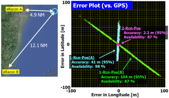
Figure 1.
Position fixing using two e-RACONS. A single beacon can provide a position, but inaccuracies measuring the bearing result in large errors that increase with distance. Two beacons used simultaneously can deliver very high accuracy (~2 m).
This potentially limits the capability of the process, since the radar requires simultaneous measurements to at least two e-RACONs for the most accurate performance. The RACONs may only have a maximum visible range of about 10–15 NM, which requires deploying at least two e-RACONS for every 10 NM of coastline. The need to provide this hardware with associated maintenance and management costs led us to consider alternative approaches.
2.2. Image Matching
Image matching is the basic process of performing dead reckoning (DR) positioning by comparing the current image on the radar screen to one taken some time earlier at a known location. Indeed, this is not a new idea [5]. GRAD installed their own “black box” Voyage Data Recorder (VDR) on one of the GLA’s vessels. This device captures an image from the vessel’s radar screen at regular intervals. It also archives other navigation data such as NMEA 0183 messages output from the GNSS receiver and other on-board sensors. The DR process then works as follows:
- A screen grab is taken from the radar.
- Digital processing of this image extracts the targets that are currently visible to the radar. This image is associated to a GNSS-derived latitude and longitude position. This is shown in Figure 2.
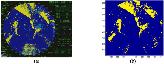 Figure 2. Capturing the radar screen for navigation. (a) A screen grab taken from the ship’s radar. (b) Target data is processed by eliminating artefacts such as AIS targets, trails and vectors. Noise from the ship’s “blind sector” is also removed.
 - Later, another image is captured, and the same processing is performed. The two images are then overlaid, and a best-fit alignment between the two is found.
- Image correlation is used to determine the best alignment of both images: Pixels that represent targets in both images count as +1. Pixels that differ count as zero. A simple summation over all image pixels determines the correlation metric. Different pixel-offsets are tested, and the alignment with the strongest correlation is selected.
- The number of pixels offset between the two images is then translated into a movement of the vessel across the sea. A new position solution is derived based on the latitude and longitude of the old image and the distance travelled by the ship. For this reason, we call the process radar dead reckoning.
Two significant aspects have been observed by GRAD when using this process:
- The correlation to the reference image falls very rapidly as the ship sails away from the location at which the image was taken.
- The error in the position solution computed by the image-matching process increases as the image correlation drops.
This process can fix the vessel’s position to within an accuracy of about 10–20 m, but only while the ship is within about half the radar range of the reference image. For example, with a radar range setting of 6 Miles, if the ship loses its GPS position, image matching can provide an accurate radar DR solution, but only for about the next 3 Miles of sailing. Depending on the speed of the vessel, this process may only be viable for a few minutes.
GRAD has investigated using more than one reference image for matching. Screen grabs can be taken regularly from the radar, and laid down as a “trail of breadcrumbs” to follow home. This is useful, especially if the vessel returns to an area it has previously been and allows accurate radar DR to operate for an extended time without GPS. However, it cannot help a vessel sailing into an area it has not previously visited. A solution to this is to pre-survey an area (e.g., a harbour approach) and publish a map of radar-conspicuous targets.
2.3. Radar Conspicuity Mapping
A logical extension to the trail of breadcrumbs process is to pre-survey the harbour, gathering a large number of radar images, and to process these into a single, authoritative radar map of the region. This map consists of a large grid of pixels covering the whole harbour area, with the value assigned to each pixel related to the strength and consistency of the radar returns seen at that location.
This process can be automated relatively easily: strong, reliable targets that appear across multiple images are given larger values in the map; weak or intermittent targets that are inconsistent across images are given lower values (Figure 3).
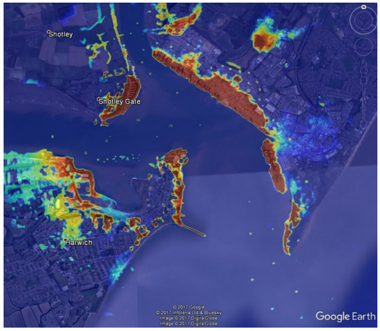
Figure 3.
Radar conspicuity map of Harwich and Felixstowe, derived from the ship’s radar and overlaid onto Google Earth. Hotter colours represent stronger, more reliable targets.
Wherever the vessel is in this area, it can then match the image on its radar screen to the conspicuity map of the area. The same image-correlation process described above is used, and trials have shown that this allows the vessel to fix its position reliably within about 30 m and achieve a 95% accuracy performance of about 20 m (Figure 4).
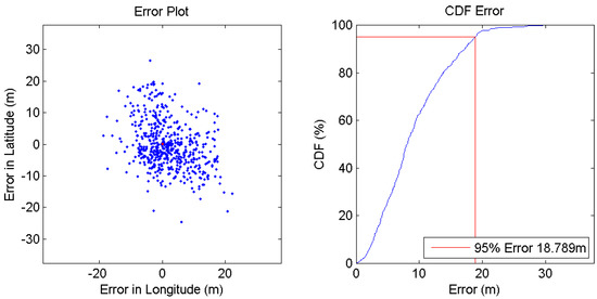
Figure 4.
Error scatter and CDF for position-fixing using image matching to the above conspicuity map.
2.4. Terrain Matching
There exist concerns that a radar conspicuity map measured by one vessel may not be usable by other vessels. Issues such as radar configuration; sea and clutter settings; and the height of the antenna will mean different ships in the same area may see very different radar targets on their screens. It also takes a large amount of time and effort to survey a harbour, so GRAD has investigated using models of terrain elevation to automate the process of determining radar conspicuity maps.
We developed a process for generating simulated radar returns from the Digital Terrain Elevation Database (DTED), which is available for free at various resolutions down to a post-spacing of about 30 m. By employing a ray-tracing process and a simple 3D illumination model, GRAD can determine modelled radar conspicuity maps for any vessel configuration. An example of this process is shown in Figure 5.
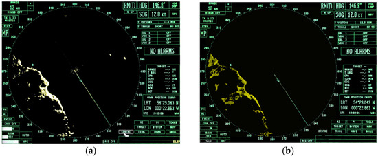
Figure 5.
Example radar conspicuity generated from a terrain database: (a) a real radar image captured from a vessel; (b) the same image with the radar returns replaced with simulated data.
To the human eye, these simulated images do look quite realistic, and the process does work reasonably reliably. However, the absolute accuracy performance so far has been poor (~100 m accuracy, 95%). This is thought to be due to issues such as the quality of the terrain data; the accuracy of the datum used; and the absence of radar returns from man-made structures in the simulated maps. GRAD has paused our research into terrain-matching pending the availability of more suitable terrain data.
2.5. Simultaneous Location and Mapping (SLAM)
If the ship is able to build its own conspicuity map as it sails, then this alleviates the need to perform extensive surveys and also solves the problem of whether the map is compatible between different ships’ radar setups. However, this still leaves the problem of a vessel sailing into an area that it has not previously visited, and therefore does not have pre-existing conspicuity data to fall back on. The solution is Simultaneous Location and Mapping (SLAM) [6]. This allows the ship to continue building its conspicuity map, even if GNSS is lost, by using the radar-derived navigation solution as a ground-truth for mapping new radar-conspicuous targets.
Our trials have shown it is possible to perform extended runs on radar SLAM, even using only a single GNSS-fixed image to start the process. A number of significant issues with the process have been observed, most notably that errors in the heading data (from the ships gyrocompass) translate into rotational errors in the map datum, which then translate into significant position errors as the ship sails. The relationship between image pixels and the physical distance across the ground also needs to be carefully calibrated: for example, we have seen that with the radar set at a 1.5 nautical mile range, targets 1.6 NM from the vessel are visible on the screen. It is thought that the real-world implementation of radar SLAM on a vessel will require a substantial calibration process first to remove artefacts such as these from the system.
GRAD has also investigated using the ship’s own speed log and gyrocompass sensors to perform “traditional” dead reckoning and has constructed a combined system-of-systems that integrates radar and traditional DR. This integration provides two useful pieces of information to the combined system:
- Traditional DR can provide the initial Estimated Position (EP) of the vessel so the map-matching process has a relatively accurate position to begin with.
- The inherent errors and biases in the speed log and gyro can be calibrated out by comparing the difference between the radar-derived navigation solution and the EP given by the DR process.
The result of our work is that the error in the solution can be reliably constrained to within less than about 25 m, even after sailing for several hours without GPS in previously un-surveyed areas. Figure 6 shows the results of a trial of traditional DR, both with and without radar aiding.
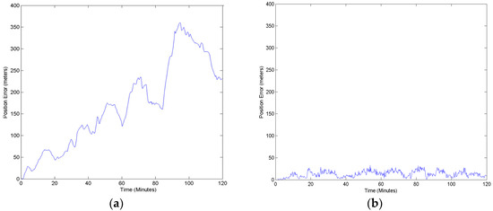
Figure 6.
Error growth over time: (a) using traditional log-and-gyro dead reckoning; (b) when radar SLAM is used to calibrate errors and biases in the DR sensors.
The combined system results in a 95% accuracy performance that has been shown to be reliably better than about 20 m. Figure 7 shows the scatter of position errors vs a DGPS ground-truth reference.
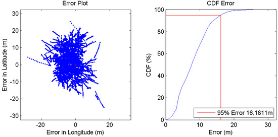
Figure 7.
Error vs. GPS for a combined radar SLAM and DR solution.
So far, this is the most accurate and reliable radar positioning GRAD has been able to achieve. Work is currently underway to obtain access to the raw data output from the radar itself and to process this data directly in the radar SLAM algorithm. The use of a processed image captured from the radar screen is probably sub-optimal, as a number of artefacts have been added to the image to aid human interpretation, not least the overlay of other navigation information such as AIS targets and vectors. It is thought that an integrated system employing raw radar data, plus log-and-gyro DR should enable resilient position fixing in line with the 10 m (95%) accuracy requirement the IMO has set for electronic position-fixing systems [7]. This is what our future research into the technology will investigate.
3. Conclusions
GRAD has investigated a number of different radar absolute positioning techniques, these are summarised in Table 1, below.

Table 1.
Summary of the radar position-fixing methods investigated by GRAD.
It is envisaged that national maritime authorities may select a mixture of approaches depending on the most appropriate approach for their waters. The installation of physical hardware, such as e-RACONs may offer a better result for areas of low-lying coast with minimal radar features, while the SLAM and DR solution may perform better in areas with sufficient coastal radar returns.
Author Contributions
Conceptualization, C.H. and A.G.; methodology, C.H.; software, C.H.; validation, C.H. and A.G.; formal analysis, C.H.; investigation, C.H.; resources, GLA; data curation, C.H.; writing—original draft preparation, C.H.; writing—review and editing, C.H. and A.G.; visualization, C.H.; supervision, A.G.; project administration, C.H. and A.G.; funding acquisition, GRAD; presentation: L.H. All authors have read and agreed to the published version of the manuscript.
Funding
This research received no external funding.
Institutional Review Board Statement
Not applicable.
Informed Consent Statement
Not applicable.
Data Availability Statement
The data presented in this study are available upon request from the corresponding author.
Conflicts of Interest
The authors declare no conflict of interest.
References
- Royal Academy of Engineering. GNSS: Reliance and Vulnerabilities; RAE: London, UK, 2011.
- IMO. International Convention for the Safety of Life at Sea (SOLAS); IMO: London, UK, 1974. [Google Scholar]
- Bole, A.; Norris, A.; Wall, A. Radar and ARPA Manual Radar, 3rd ed.; Butterworth-Heinemann: Oxford, UK, 2014. [Google Scholar]
- Ward, N.; Safar, J. Enhanced Radar Positioning. In Proceedings of the 2014 International Technical Meeting of the Institute of Navigation, San Diego, CA, USA, 27–29 January 2014. [Google Scholar]
- Austin, G.L.; Bellon, A.; Riley, M.; Ballantyne, E. Navigation by Computer Processing of Marine Radar Images. J. Navig. 1985, 38, 3. [Google Scholar] [CrossRef]
- Han, J.; Cho, Y.; Kim, J. Coastal SLAM With Marine Radar for USV Operation in GPS-Restricted Situations. IEEE J. Ocean. Eng. 2019, 44, 300–309. [Google Scholar] [CrossRef]
- IMO Resolution A.1046—World Wide Radio Navigation Service; IMO: London, UK, 2011.
Disclaimer/Publisher’s Note: The statements, opinions and data contained in all publications are solely those of the individual author(s) and contributor(s) and not of MDPI and/or the editor(s). MDPI and/or the editor(s) disclaim responsibility for any injury to people or property resulting from any ideas, methods, instructions or products referred to in the content. |
© 2023 by the authors. Licensee MDPI, Basel, Switzerland. This article is an open access article distributed under the terms and conditions of the Creative Commons Attribution (CC BY) license (https://creativecommons.org/licenses/by/4.0/).