
Source Camera Linking Algorithm Based on the Analysis of Plain Image Zones †


Abstract
1. Introduction
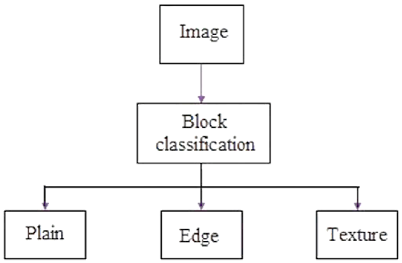
2. Proposed Method
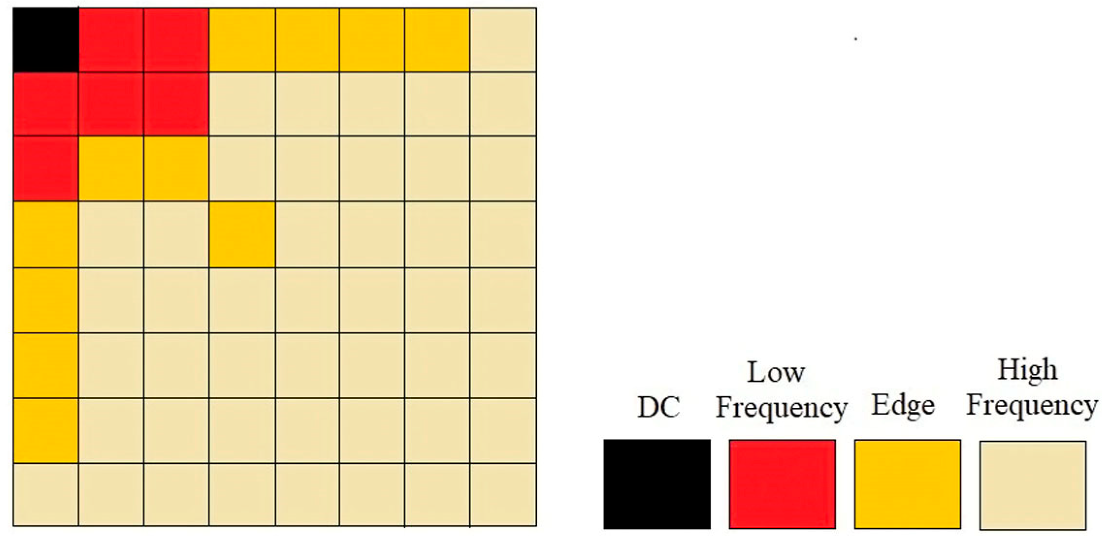
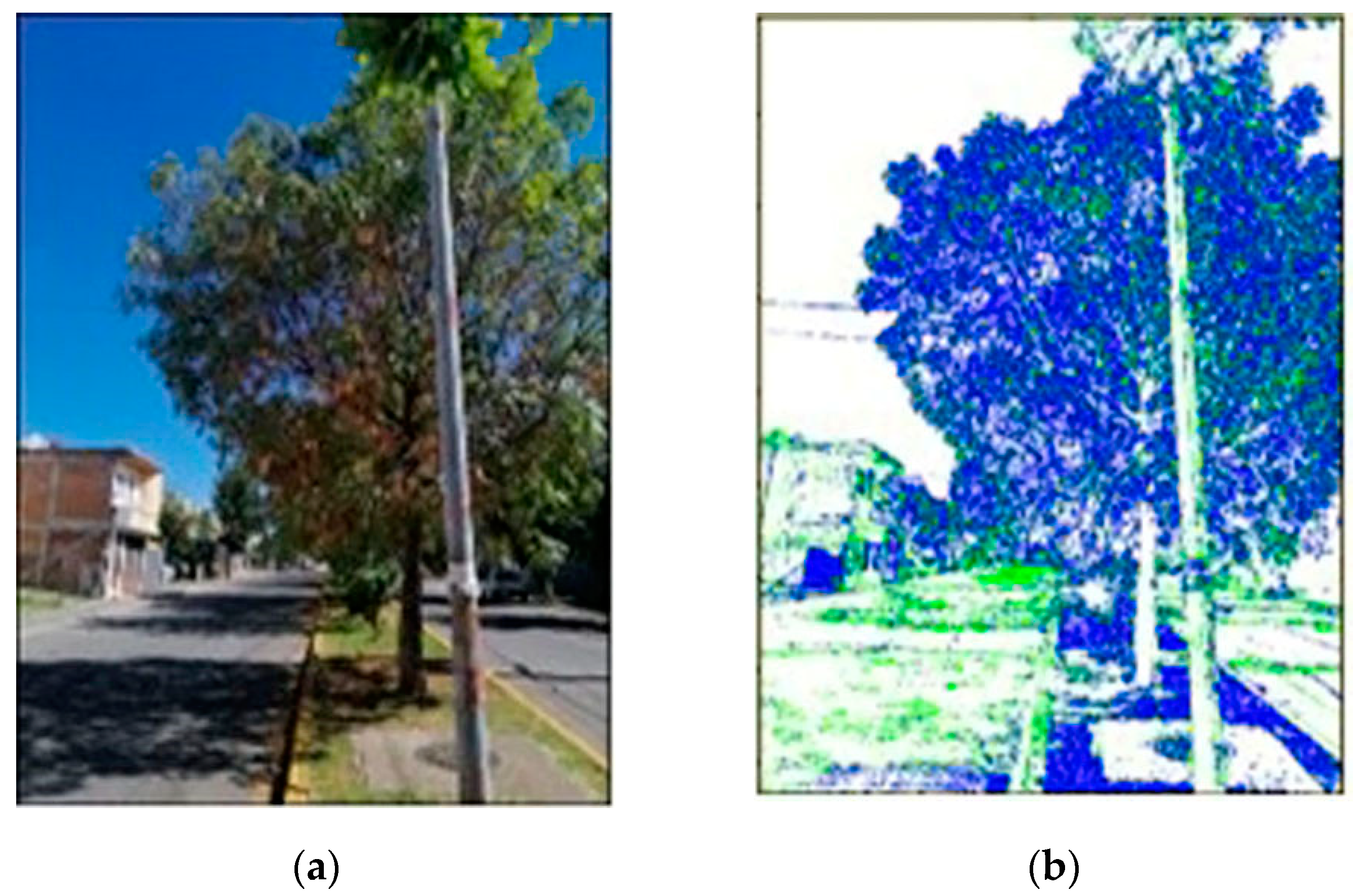
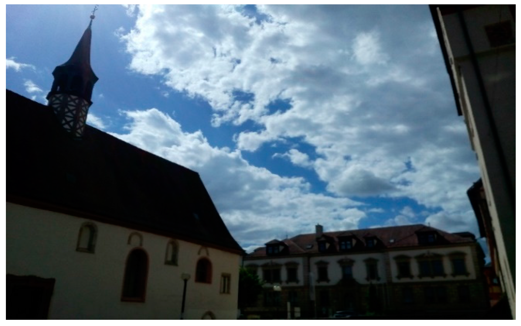
2.1. Plain Zone Segmentation
- if E + H ≤ µ2 and
- or if E + H > µ2 and
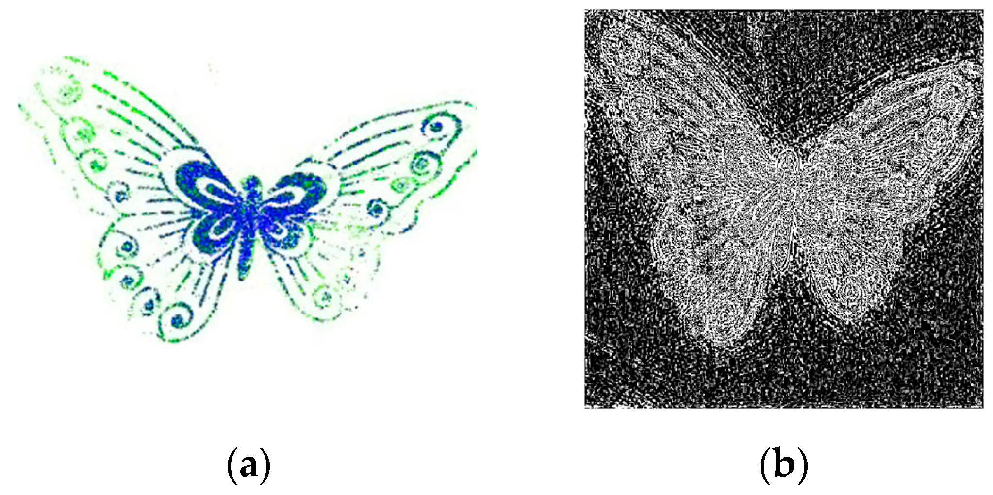
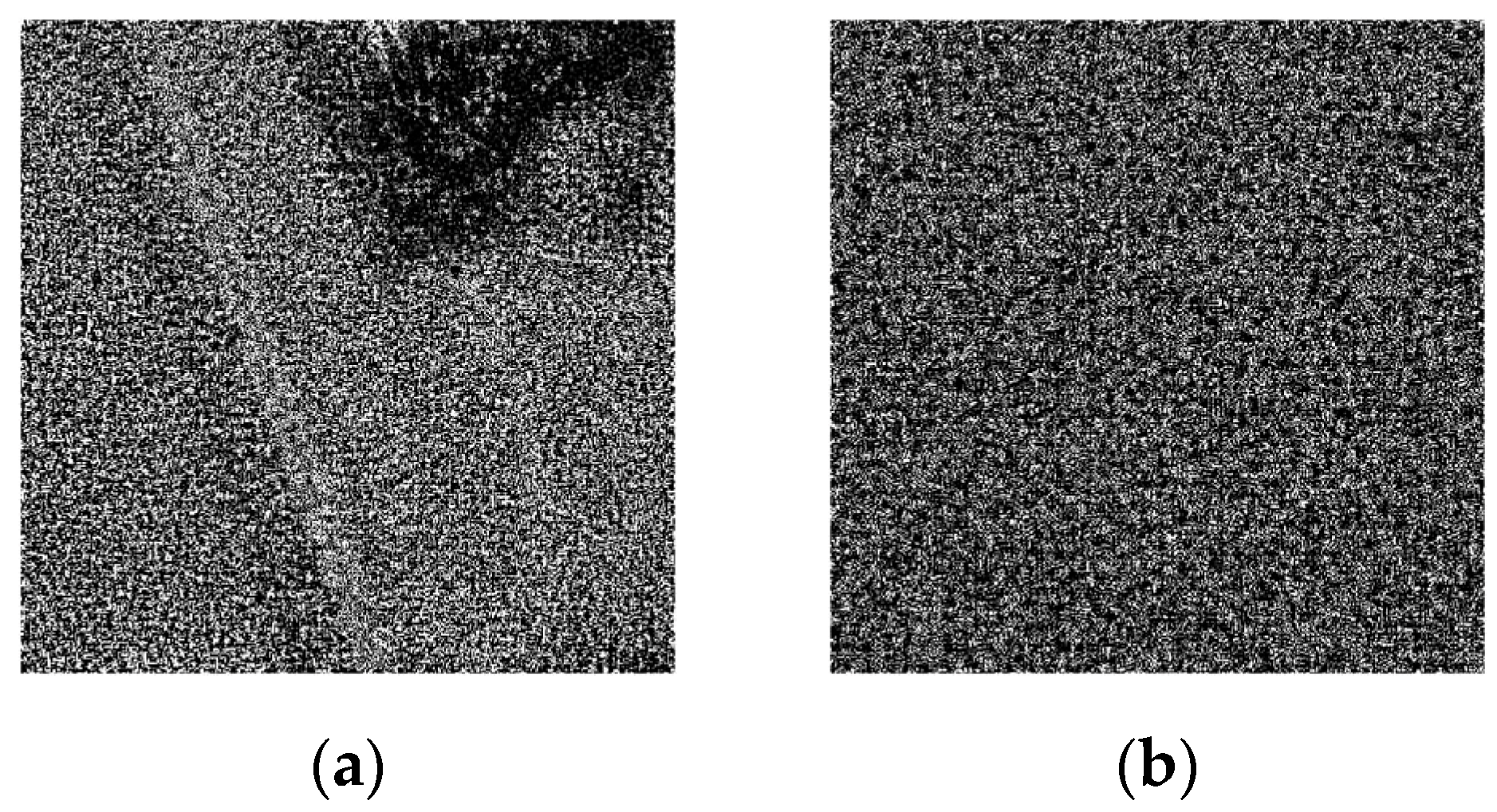
2.2. Estimation of Peak to Correlation Energy
3. Results
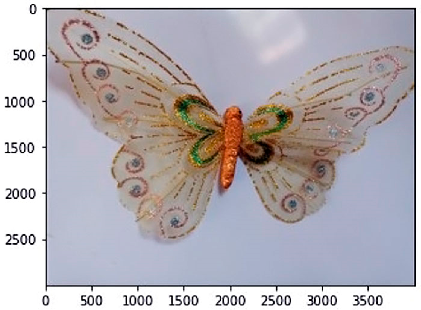
3.1. Experiment I
- The first way the image was cropped was by a single 512 × 512 plain pixel region, named ‘one zone’;
- The second way consisted of cropping sixteen plain sections of 128 × 128 pixel size, which were reassembled into a 512 × 512 pixel image, referred to as ‘zones’.
3.2. Experiment II
4. Conclusions
Author Contributions
Funding
Institutional Review Board Statement
Informed Consent Statement
Data Availability Statement
Acknowledgments
Conflicts of Interest
References
- Lukás, J.; Fridrich, J.; Goljan, M. Digital Camera Identification from Sensor Pattern Noise. IEEE Trans. Inf. Forensics Secur. 2006, 1, 205–214. [Google Scholar] [CrossRef]
- Chen, J.M.; Fridrich, J.; Goljan, M.; Jan, L. Determining Image Origin and Integrity Using Sensor. IEEE Trans. Inf. Forensics Secur. 2008, 3, 74–90. [Google Scholar] [CrossRef]
- Hu, Y.; Yu, B.; Jian, C. Source Camera Identification Using Large Components of Sensor Pattern Noise. In Proceedings of the 2nd International Conference on Computer Science and its Applications, Seoul, Republic of Korea, 10–12 December 2009. [Google Scholar]
- Tiwari, M.; Gupta, B. Image Features Dependant Correlation-Weighting Function for Efficient PRNU Based Source Camera Identification. Forensic Sci. Int. 2018, 285, 111–120. [Google Scholar] [CrossRef] [PubMed]
- Valesia, D.; Coluccia, G.; Bianchi, T.; Magli, E. User Authentication via PRNU-Based and Physical Unclonable Functions. IEEE Trans. Inf. Forensics Secur. 2008, 12, 1941–1956. [Google Scholar] [CrossRef]
- Mihcak, M.k.; Kozintsev, I.; Ramchandran, K. Spatially Adaptive Statistical Modeling of Wavelet Image Coefficients and Its Application to Denoising. In Proceedings of the IEEE International Conference on Acoustics, Speech, and Signal Processing, Phoenix, AZ, USA, 15–19 March 1999. [Google Scholar]
- Mihcak, M.k.; Kozintsev, I.; Ramchandran, K.; Moulin, P. Low-Complexity Image Denoising Based on Statistical Modeling of Wavelet Coefficients. IEEE Signal Process. Lett. 1999, 6, 300–303. [Google Scholar] [CrossRef]
- Dabov, K.; Foi, A.; Katkovnik, V.; Egiazarian, K. Image Denoising by Sparse 3-D Transform-Domain Collaborative Filtering. IEEE Trans. Inf. Forensics Secur. 2007, 1, 2080–2095. [Google Scholar] [CrossRef] [PubMed]
- Salazar, D.A.; Ramirez-Rodriguez, A.E.; Nakano, M.; Cedillo-Hernandez, M.; Perez-Meana, H. Evaluation of Denoising Algorithms for Source Camera Linking. In Proceedings of the MCPR 2021, Mexico City, Mexico, 19–22 June 2021. [Google Scholar]
- Tong, H.H.Y.; Venetsanopoulos, A.N. A perceptual model for JPEG applications based on block classification, texture masking, and luminance masking. In Proceedings of the International Conference on Image Processing, Chicago, IL, USA, 7 October 1998. [Google Scholar]
- Su, Q.; Wang, Y.; Li, Y.; Zhang, C.; Lang, P.; Fu, X. Image Denoising Based on Wavelet Transform and BM3D Algorithm. In Proceedings of the IEEE 4th International Conference on Signal and Image Processing, Wuxi, China, 19–21 June 2019. [Google Scholar]
- Li, C.T. Source Camera Identification Using Enhanced Sensor Pattern Noise. IEEE Trans. Inf. Forensics Secur. 2010, 5, 280–287. [Google Scholar]
- Hadwiger, B.; Riess, C. The Forchheim Image Database for Camera Identification in the Wild. In Proceedings of the ICPR Workshops, Milano, Italy, 10–15 January 2021. [Google Scholar]


| Number of Cameras | Brand | Model | OS | Resolution |
|---|---|---|---|---|
| Camera 1 | Motorola | E3 | Android | 3280 × 2664 |
| Camera 2 | LG | Optimus L50 | Android | 2048 × 1536 |
| Camera 3 | Wiko | Lenny 2 | Android | 2560 × 1920 |
| Camera 4 | LG | G3 | Android | 4160 × 3120 |
| Camera 5 | Apple | iPhone 6s | iOS | 4032 × 3024 |
| Camera 6 | LG | G6 | Android | 2080 × 1560 |
| Camera 7 | Motorola | Z2 Play | Android | 4032 × 3024 |
| Camera 8 | Motorola | G8 Plus | Android | 3000 × 4000 |
| Camera 9 | Samsung | Galaxy S4 mini | Android | 3264 × 2448 |
| Camera 10 | Samsung | Galaxy J1 | Android | 2592 × 1944 |
| Camera 11 | Samsung | Galaxy J3 | Android | 3264 × 2448 |
| Camera 12 | Samsung | Galaxy Star 5280 | Android | 1600 × 1200 |
| Number of Cameras | One Zone | Zones | Conventional |
|---|---|---|---|
| Camera 1 | 35.1152 | 42.1491 | 6.4015 |
| Camera 2 | 37.1227 | 44.2302 | 9.0886 |
| Camera 3 | 33.6813 | 42.7957 | 7.6214 |
| Camera 4 | 34.5184 | 45.0543 | 5.2810 |
| Camera 5 | 35.4917 | 45.0038 | 6.9693 |
| Camera 6 | 33.7016 | 40.7761 | 4.7675 |
| Camera 7 | 36.0282 | 49.5316 | 8.7290 |
| Camera 8 | 35.5511 | 44.6075 | 3.8505 |
| Camera 9 | 34.3121 | 43.5091 | 5.6535 |
| Camera 10 | 33.4316 | 41.5974 | 4.0072 |
| Camera 11 | 35.9563 | 49.4259 | 7.5803 |
| Camera 12 | 35.5768 | 43.1329 | 3.5796 |
| Number of Cameras | One Zone | Zones | Conventional |
|---|---|---|---|
| Camera 1 | 0.7037 | 0.6353 | 0.9974 |
| Camera 2 | 0.5950 | 0.5837 | 0.8295 |
| Camera 3 | 0.6174 | 0.5993 | 0.9791 |
| Camera 4 | 0.4690 | 0.3725 | 0.6912 |
| Camera 5 | 0.5424 | 0.5278 | 0.7859 |
| Camera 6 | 0.4785 | 0.3942 | 0.9171 |
| Camera 7 | 0.6315 | 0.6138 | 0.8450 |
| Camera 8 | 0.5101 | 0.4496 | 0.7488 |
| Camera 9 | 0.5673 | 0.4569 | 0.8922 |
| Camera 10 | 0.5415 | 0.4110 | 0.9822 |
| Camera 11 | 0.5259 | 0.4912 | 0.7551 |
| Camera 12 | 0.4772 | 0.2951 | 0.8825 |
Disclaimer/Publisher’s Note: The statements, opinions and data contained in all publications are solely those of the individual author(s) and contributor(s) and not of MDPI and/or the editor(s). MDPI and/or the editor(s) disclaim responsibility for any injury to people or property resulting from any ideas, methods, instructions or products referred to in the content. |
© 2024 by the authors. Licensee MDPI, Basel, Switzerland. This article is an open access article distributed under the terms and conditions of the Creative Commons Attribution (CC BY) license (https://creativecommons.org/licenses/by/4.0/).
Share and Cite
Ramirez-Rodriguez, A.E.; Nakano, M.; Perez-Meana, H. Source Camera Linking Algorithm Based on the Analysis of Plain Image Zones. Eng. Proc. 2024, 60, 17. https://doi.org/10.3390/engproc2024060017
Ramirez-Rodriguez AE, Nakano M, Perez-Meana H. Source Camera Linking Algorithm Based on the Analysis of Plain Image Zones. Engineering Proceedings. 2024; 60(1):17. https://doi.org/10.3390/engproc2024060017
Chicago/Turabian StyleRamirez-Rodriguez, Ana Elena, Mariko Nakano, and Hector Perez-Meana. 2024. "Source Camera Linking Algorithm Based on the Analysis of Plain Image Zones" Engineering Proceedings 60, no. 1: 17. https://doi.org/10.3390/engproc2024060017
APA StyleRamirez-Rodriguez, A. E., Nakano, M., & Perez-Meana, H. (2024). Source Camera Linking Algorithm Based on the Analysis of Plain Image Zones. Engineering Proceedings, 60(1), 17. https://doi.org/10.3390/engproc2024060017